1
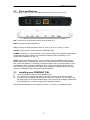
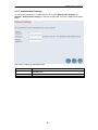
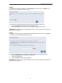
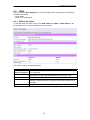
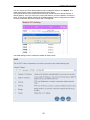
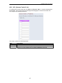
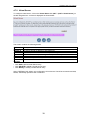
FREEWAY DSL User’s Manual
ADSL2+ USB/Ethernet Combo Bridge Router
Freeway DSL User’s Manual
Revision 0.2
March 2008
FREEWAY DSL User’s Manual
Table of Contents
1.
INTRODUCTION......................................................................................................................... 1
1.1
1.2
2.
FEATURES .............................................................................................................................. 1
SYSTEM REQUIREMENT .......................................................................................................... 1
FREEWAY DSL OVERVIEW.................................................................................................... 2
2.1
2.2
2.3
3.
LED DESCRIPTION ................................................................................................................. 2
PORTS AND BUTTONS ............................................................................................................. 3
INSTALLING YOUR FREEWAY DSL ..................................................................................... 3
SETTING UP YOUR FREEWAY DSL...................................................................................... 4
3.1
4.
LOG INTO YOUR FREEWAY DSL......................................................................................... 4
ADVANCED SETUP.................................................................................................................... 6
4.1
4.1.1
4.1.2
4.1.3
4.1.4
4.1.5
4.1.6
4.1.7
4.2
4.2.1
4.2.2
4.3
4.3.1
4.3.2
4.4
4.4.1
4.4.2
SYSTEM .................................................................................................................................. 7
Host Name Config............................................................................................................. 7
System Time ...................................................................................................................... 8
Administrator Settings ...................................................................................................... 9
Firmware Upgrade ......................................................................................................... 10
Configuration Settings .................................................................................................... 10
System Log...................................................................................................................... 12
Reset ............................................................................................................................... 13
STATISTICS ........................................................................................................................... 13
LAN Statistics ................................................................................................................. 13
WAN Statistics ................................................................................................................ 14
ADSL .................................................................................................................................. 15
ADSL Line Status............................................................................................................ 15
ADSL PHY Configuration............................................................................................... 16
WAN ................................................................................................................................... 17
ADSL VC Configuration ................................................................................................. 17
WAN Settings .................................................................................................................. 19
Dynamic IP .............................................................................................................................................. 21
Static IP.................................................................................................................................................... 21
PPPoE ...................................................................................................................................................... 23
PPPoA...................................................................................................................................................... 24
Bridge....................................................................................................................................................... 24
4.4.3
4.4.4
4.4.5
4.4.6
4.5
4.5.1
4.5.2
4.5.3
4.5.4
4.5.5
4.6
4.6.1
4.6.2
4.6.3
4.6.4
4.6.5
4.6.6
4.7
4.7.1
4.7.2
4.7.3
4.8
4.8.1
WAN Status ..................................................................................................................... 25
Domain Name Server (DNS)........................................................................................... 26
VLAN Configuration....................................................................................................... 26
ADSL OAM Configuration ............................................................................................. 27
LAN..................................................................................................................................... 28
LAN Settings ................................................................................................................... 28
DHCP Client List............................................................................................................ 29
Static Routing ................................................................................................................. 29
Routing Table List .......................................................................................................... 30
IPv6................................................................................................................................. 31
FIREWALL ............................................................................................................................ 31
Firewall Settings............................................................................................................. 31
Packet Filtering .............................................................................................................. 32
Parental Control............................................................................................................. 34
Application Filtering ...................................................................................................... 35
Application Server Settings............................................................................................. 35
ACL (Access Control List) .............................................................................................. 37
NAT..................................................................................................................................... 38
NAT (Network Address Translation) Settings................................................................. 38
Virtual Server ................................................................................................................. 39
DMZ (Demilitarized Zone) ............................................................................................. 40
DEVICE MANAGEMENT ........................................................................................................ 41
SNMP (Simple Network Management Protocol) ............................................................ 41
FREEWAY DSL User’s Manual
APPENDIX. TROUBLESHOOTING ................................................................................................ 42
FREEWAY DSL User’s Manual
1.
Introduction
The FREEWAY DSL ADSL2+ USB Ethernet Combo Bridge Router provides sharing the
broadband connection through the Fast Ethernet LAN port and 24Mbps high speed
downstream via the USB 2.0 device port.
The FREEWAY DSL is compatible with ADSL, ADSL2, and ADSL2+ lines for connecting to
the Internet and combines the NAT and NAPT functions for sharing and a firewall for security.
It can be easily configured through a web-browser interface, with a built-in setup wizard to
guide user through initial setup.
1.1
Features
Comply with ITU ADSL, ADSL and ADSL2+ standards
Comply with IEEE802.3/802.3u 10/100 BASE-T standards
USB 2.0 device port provides full ADSL2+ download speed
Enables sharing of broadband Internet connection
Double firewalls: NAT and SPI
Built-in DHCP server
Mac address filtering
VPN pass-through
Web-based advanced user interface
SNMP, DMZ, port mapping, port forwarding (optional)
TR-068 compliance
1.2
System Requirement
In order to use the FREEWAY DSL, you must have the following:
ADSL service up and running on your telephone line, with at least one public Internet
address for your LAN
One or more computers each containing an Ethernet network interface card (NIC) and/or
a single computer with a USB port
An Ethernet hub/switch, if you are connecting the device to more than one computer on
an Ethernet network
For system configuration using the supplied web-based program: a web browser such as
Internet Explorer v5.0 or later, Firefox v2.0 or later, or Netscape v6.1 or later
1
FREEWAY DSL User’s Manual
2.
FREEWAY DSL Overview
Your FREEWAY DSL has many ports, LEDs and button. The features are listed below.
2.1
LED Description
The front panel contains lights called LEDs that indicate the status of the FREEWAY DSL.
LED
POWER
LAN
USB
DSL
Internet
Status
On
Off
On
Blinking
Off
On
Blinking
Off
On
Blinking
Off
On
Blinking
Off
Description
The device is power on.
The device is power off.
The LAN port is connected to Ethernet device.
The data is sending/receiving via LAN port.
The LAN port is not connected to Ethernet device.
The device is successfully connected to a USB equipped device.
The data is sending/receiving via USB port.
The device is not connected to a USB equipped device.
The device is successfully linked with ADSL line (DSLAM).
The device is trying to link with ADSL line (DSLAM).
The device is not linked with ADSL line (DSLAM).
The device is successfully connected to Internet.
The device is sending/receiving data from Internet.
The WAN port is not connected to Internet.
2
FREEWAY DSL User’s Manual
2.2
Ports and Buttons
The rear panel contains the ports for the FREEWAY DSL's data and power connections.
DSL: Connecter for accessing the Internet through ADSL line.
USB: Connector for USB equipped PC.
LAN: Connector for Ethernet network devices, such as a PC, hub, switch, or router.
ON/OFF: Power switch to power on/off the FREEEWAY DSL.
POWER: Connecter for a power adapter. Using a power supply with a different voltage rating
will damage this product. Make sure to observe the proper power requirements. The
requirement of adapter is 9V AC/ 1A.
RESET: Restore the default settings. You may need to place the FREEWAY DSL into its
factory defaults if the configuration is changed, you loose the ability to enter the FREEWAY
DSL via the web interface, or following a software upgrade, and you loose the ability to enter
the FREEWAY DSL. To reset the FREEWAY DSL, simply press the reset button for more
than 5 seconds. The FREEWAY DSL will be reset to its factory defaults and after about 30
seconds the FREEWAY DSL will become operational again.
2.3
1.
2.
3.
Installing your FREEWAY DSL
Locate an optimum location for the FREEWAY DSL.
For connections to the Ethernet and DSL interfaces, refer to the Quick Start Guide.
Connect the Power Adapter. Depending upon the type of network, you may want to put
the power supply on an uninterruptible supply. Only use the power adapter supplied with
the FREEWAY DSL. A different adapter may damage the product.
The hardware installation is now complete, continue on to set up your FREEWAY DSL.
3
FREEWAY DSL User’s Manual
3.
Setting up Your FREEWAY DSL
This section guides you through configuring your FREEWAY DSL. Before setting up your
FREEWAY DSL, make sure you have followed the Quick Start Guide. You should have your
computers configured for DHCP mode and have proxies disabled on your browser. If you do
not get the page as shown below, you may need to delete your temporary Internet files by
flushing the cached web pages.
3.1
Log into Your FREEWAY DSL
Use the following procedures to log in to your FREEWAY DSL.
1. Open your web browser. Type the default IP address of the Freeway DSL
http://192.168.1.1 and press Enter.
The Welcome page appears.
2.
3.
Enter user name as admin and password as admin (case sensitive).
Click OK.
The main page appears.
Note
You can change the password from System then Administrator Settings page
at any time.
4
FREEWAY DSL User’s Manual
The Web Application is displayed as shown below.
Web configuration can be done by Administrators. Administrators have the right to configure
all the options available in the Web interface.
Field
LAN
IP Address
Subnet Mask
DHCP Mode
Connected Clients
Firewall
Physical Port Status
PORT-0
Information
Bootloader Version
BSP Version
ADSLRT Software
Version
ADSLRT Tool Chain
Version
ADSLRT Firmware
Version
Description
Shows the local IP address of ADSL CPE.
Shows the local subnet mask of ADSL CPE.
Shows whether DHCP client is enabled for LAN.
Disabled
Server: If the DHCP mode is Server, there is an additional piece
of information on the number of connected clients.
Relay Agent
Shows the number of connected clients to FREEWAY DSL.
Shows the status of Firewall
Shows the port status of FREEWAY DSL.
Shows the current version loaded.
Shows the current version loaded.
Shows the current version of ADSL CPE loaded on the device.
Shows the current tool chain version used to generate the software
image.
Shows the current version of ADSL firmware loaded on the device.
5
FREEWAY DSL User’s Manual
4.
Advanced Setup
This chapter is only for Administrators. The Homepage is the first screen displayed when you
log on to the FREEWAY DSL Web Application. To log on to the Web Application, you must
have a valid user name and password. To continue configuring Web Application, click on
Advanced Setup.
Advanced setup page in Web Application allows you to configure features like Firewall,
routing, VoIP etc. Click “Advanced Setup” link found on top in the homepage. The following
modules are displayed in the left navigation bar:
System
Statistics
ADSL
WAN
LAN
Firewall
NAT
Device Management
6
FREEWAY DSL User’s Manual
4.1
System
You can view the System from the left navigation bar. The following options are available
under System:
Host Name Configuration
System Time
Administrator Settings
Firmware Upgrade
Configuration Settings
System Log
Reset
4.1.1 Host Name Config
To configure System settings, you have to enter host and domain name. Click Host Name
Config link (System > Host Name Config) in the left navigation bar, a screen is displayed
below:
cpe
cpe.com
The screen contains the following details:
Field
Host Name
Domain Name
Description
To enter the host name of the FREEWAY DSL. This is used to address
FREEWAY DSL by using this name instead of typing the IP address.
To enter the domain name of the FREEWAY DSL.
7
FREEWAY DSL User’s Manual
4.1.2 System Time
To configure your time zone and the SNTP (Simple Network Time Protocol) server, click on
the System Time link (System > System Time) in the left navigation bar. A screen is
displayed as shown below.
The screen contains the following details:
Field
Set Time Zone
SNTP Client
SNTP Server
Description
Select the time zone where you resident.
To enable/disable SNTP client function. You must enable SNTP client to
allow updating system clock.
Select the network time server for the FREEWAY DSL to synchronized
with.
8
FREEWAY DSL User’s Manual
4.1.3 Administrator Settings
To change the password for the administrator, click on the Administrator Settings link
(System > Administrator Settings) in the left navigation bar. A screen is displayed as shown
below.
The screen contains the following details:
Field
Current Password
Password
Re-type Password
Description
Enter the current password the administrator used to login to the
FREEWAY DSL.
Enter the new password you want to change.
Enter the new password again to confirm the password.
9
FREEWAY DSL User’s Manual
4.1.4 Firmware Upgrade
To update the system firmware, click on the Firmware Upgrade link (System > Firmware
Upgrade) on the left navigation bar. A screen is displayed as shown below.
To upgrade firmware, please follow the following instructions:
1.
Click the Browse button to select the firmware file.
2.
Confirm your selection.
3.
Click the APPLY button to start upgrading.
IMPORTANT! Do NOT power off the FREEWAY DSL or press the Reset button while this
procedure is in progress.
4.1.5 Configuration Settings
To backup your current configuration or restore a previously saved configuration, click on the
Configuration Settings link (System > Configuration Settings) in the left navigation bar. A
screen is displayed as shown below.
10
FREEWAY DSL User’s Manual
Backup
To backup your current configuration, select Backup radio button and click APPLY. The
backup screen is displayed as shown below.
To backup your current configuration, please follow the following instructions:
1.
Click the Backup button to backup the configuration file.
2.
Select the location to save the file. The file will be in gzipped (.gz) format.
IMPORTANT! Do NOT power off the FREEWAY DSL or press the Reset button while this
procedure is in progress.
Restore
To restore a previously saved configuration, select Restore radio button and click APPLY.
The restore screen is displayed as shown below.
To restore a previously saved configuration, please follow the following instructions:
1.
Click the Browse button to select the firmware file.
2.
Confirm your selection.
3.
Click the APPLY button to start upgrading.
IMPORTANT! Do NOT power off the FREEWAY DSL or press the Reset button while this
procedure is in progress.
11
FREEWAY DSL User’s Manual
4.1.6 System Log
To view the system logs, click on the System Log link (System > System Log) in the left
navigation bar. A screen is displayed as shown below.
The screen contains the following details:
Field
Description
Configure System Select the location to log the events.
Local: The events are logged locally in the system.
Log
Remote: The events are logged to a remote server. You must specify
the IP address of remote server and UDP port number.
Local and Remote: The events are logged locally in the system and
the remote server.
Select the log level to record from the drop-down list.
Filter Level
Click this button to confirm the filter level you select.
Save Changes
View System Log Select the log level to view from the drop-down list.
Click this button to view recorded logs.
View Log
In the System Log records page, you can:
System Log
Click Download to download the log file to your computer.
Click Clear to clear this page.
Click Refresh to retrieve system event and update the log file.
Click Back to return to System Log configuration page.
12
FREEWAY DSL User’s Manual
4.1.7 Reset
To reboot the system, click on the Reset link (System > Reset) in the left navigation bar. A
screen is displayed as shown below.
Click Reset to reboot the system without change any settings.
Click Factory Reset to reboot the system with default factory settings.
4.2
Statistics
The Statistics contains the statistics of every interface. The following are the options
available under Statistics:
LAN
WAN
4.2.1 LAN Statistics
To view the LAN statistics, click on the LAN link (Statistics > LAN) in the left navigation bar.
A screen is displayed as shown below.
13
FREEWAY DSL User’s Manual
4.2.2 WAN Statistics
To view the WAN statistics, click on the WAN link (Statistics > WAN) in the left navigation
bar. A screen is displayed as shown below.
14
FREEWAY DSL User’s Manual
4.3
ADSL
You can view the ADSL Settings from the left navigation bar. The following are the options
available under ADSL:
ADSL Status
ADSL PHY Configuration
4.3.1 ADSL Line Status
To view the ADSL line status, click on the ADSL Status link (ADSL > ADSL Status) in the
left navigation bar. A screen is displayed as shown below.
The screen contains the following details:
Field
ATU-C System
Vendor Information
Status
Rate
Information
Performance
Description
Displays the Vendor ID, Version Number and the Serial Number of the
ATU-C (DSLAM).
Displays the status of the physical ADSL Line in terms of the modem,
mode selected, Trellis-Coded Modulation and the Latency Type.
Displays the data rate and the maximum attainable data rate.
Displays the information about the ADSL line, in terms of Line
Attenuation, Signal Attenuation, Signal to Noise Ratio and other such
parameters.
Displays the performance of the physical ADSL line.
15
FREEWAY DSL User’s Manual
4.3.2 ADSL PHY Configuration
To configure the PHY (physical layer) settings, click on the ADSL PHY Configuration link
(ADSL > ADSL PHY Configuration) in the left navigation bar. A screen is displayed as
shown below.
The screen contains the following details:
Field
ATU
Transmission
system Enabling
Testmode Control
Description
Select the Annex mode from the drop-down list. The mode you select will
reflect to the matrix of Manual Configuration of ATU Transmission
System Enabling Table below.
Select the test mode control method:
Disable
Showtime Lock: Showtime lock is used for firmware debug. if the
showtime lock enable, the autoboot daemon will not reset arc when
the arc reach showtime and need to reboot.
The following sequence must be followed:
1.
Reboot
2.
Enter Showtime state
3.
Check for the absence of upstream showtime signal.
4.
Click Showtime Lock button. After that, the message
“ShowtimeLock Configuration successful” appears.
5.
Unplug the DSL line
6.
Check for the presence of upstream showtime signal.
Note: The showtime signal is persistent and no ADSL DFE reboot
happens. Press Get button to display the bits allocated per tone.
Quiet Mode: Quiet mode is used for firmware debug. if the quiet
mode enable, the autoboot daemon will not reset arc when the arc
need to reboot.
The following sequence must be followed:
1.
Reboot and then check for the presence of handshake tones.
2.
Click Quiet Mode button, the message “QuietMode Configuration
Successful!” appears.
3.
Check for the absence of handshake tones.
16
FREEWAY DSL User’s Manual
Note: HS tones disappear, the waveform becomes idle and no retrain
happens.
L0: The L0 state is the mode of normal operation. The full data rate for
Power
a given environment can only be achieved when the ADSL link is in
Management
the L0 state.
Control
L3: The L3 state is the mode when no signal is transmitted on the line,
and thus no transmission of information is possible.
Bits Allocated per Tone
Displays the bit allocation status of a specific tone and each ADSL tone.
US BAT /
DS BAT
4.4
WAN
You can view WAN settings from the left navigation bar. The following are the options
available under WAN:
VC Configuration
WAN Setting
WAN Status
DNS (Domain Name Server)
WAN VLAN Config
OAM Configuration
4.4.1 ADSL VC Configuration
To configure the ATM PVC (Permanent Virtual Connection) settings, click on the VC
Configuration link (WAN > VC Configuration) in the left navigation bar. A screen is
displayed as shown below.
17
FREEWAY DSL User’s Manual
The screen contains the following details:
Field
Description
Encapsulation The encapsulation can be configured to:
LLC/SNAP
Mode
VCMUX
To enter the VPI and VCI provided by your ISP.
VPI/VCI
setting
FREEWAY DSL Supports the following ATM QoS traffic classes per VC:
QoS Mode
UBR: Unspecified Bit Rate.
CBR: Constant Bit Rate.
NRT-VBR: Variable Bit Rate-non real time.
When you select this option for QoS mode, the following additional fields
become available: Minimum Cell Rate, Sustainable Cell Rate, Maximum
Burst Size.
RT-VBR: Variable Bit Rate-real time.
When this option is selected for QoS mode, the following additional fields
become available: Sustainable Cell Rate, Maximum Burst Size.
UBR+: This is a special service class derived from UBR.
When QoS Mode is set to this option, the following field appears
additionally: Minimum Cell Rate.
Peak Cell Rate This parameter is required for all ATM traffic classes and is configured in
cells/s.
This parameter is required for VBR-rt (Variable Bit Rate - real time)
Cell Delay
connections. It will only be displayed for this traffic class. The value is
Variation
specified in ms to specify the maximum allowed jitter.
18
FREEWAY DSL User’s Manual
4.4.2 WAN Settings
To configure the WAN interface, click on the WAN Setting link (WAN > WAN Setting) on the
left navigation bar. A screen is displayed as shown below.
FREEWAY DSL supports up to 15 VCCs. This page shows the default interface and the
default gateway configured on the device. You can click on any of the radio buttons to select
the default interface or the default gateway.
19
FREEWAY DSL User’s Manual
You can choose one of the WAN interfaces being configured and then click APPLY. The
WAN configuration screen will then displayed as shown below.
This page shows the action performed on clicking any radio button for default interface or
default gateway. Once you click on any of the radio buttons you will be asked to confirm the
same. If click OK the default interface or the default gateway will be configured on the WAN
connection selected. Otherwise changes will not be applied.
The WAN Settings screen contains the details as shown below.
20
FREEWAY DSL User’s Manual
The screen contains the following details:
Field
Attached Channel
Dynamic IP
Address
Static IP Address
PPPoE
PPPoA
Bridge
Delete
Description
This is the PVC being configured.
To get your IP Address from your service provider (means FREEWAY
DSL is DHCP client on the WAN) click APPLY.
To enter the WAN interface IP Address of FREEWAY DSL enable this
field and click APPLY.
Point-to-Point Protocol over Ethernet used for connecting to the ISP,
click APPLY.
Point-to-Point Protocol over ATM used for connecting to the ISP, click
APPLY.
To enter the Bridge Configuration (RFC2684) of FREEWAY DSL
enable this field and click APPLY.
To delete this VCC setting.
Dynamic IP
To configure the WAN interface to dynamically obtain an IP address, select the Dynamic IP
Address button on the WAN settings page and click APPLY. A screen is displayed as
shown below.
The screen contains the following details:
Field
Protocol
Description
This option allows to select the protocols:
RFC 2684 Ethernet over ATM
RFC 2364 IP over ATM
To enter the VLAN ID for which membership needs to be added for the
VLAN ID
selected port.
VLAN Priority Specify the priority of VLAN.
Tagging outgoing frames with VLAN-Tagged.
TAG
Untagging outgoing frames with VLAN-Tagged.
UN-TAG
Static IP
To configure the WAN interface to use a static IP address, select the Static IP Address
button on the WAN settings page and click APPLY. A screen is displayed as shown below.
21
FREEWAY DSL User’s Manual
The screen contains the following details:
Field
IP address
assigned by your
ISP
Subnet Mask
ISP Gateway
Address
Protocol
VLAN ID
VLAN Priority
TAG
UN-TAG
Description
To enter the IP Address of FREEWAY DSL.
To enter the Subnet Mask of FREEWAY DSL.
To enter the Gateway address of the FREEWAY DSL.
Select the supported Protocol:
Classic IP, which is the classical IP over ATM
RFC 2684 Ethernet over ATM
RFC 2684 IP over ATM
To enter the VLAN ID for which membership needs to be added for the
selected port.
Specify the priority of VLAN.
Tagging outgoing frames with VLAN-Tagged.
Untagging outgoing frames with VLAN-Tagged.
22
FREEWAY DSL User’s Manual
PPPoE
To configure the WAN interface to use PPPoE, select the PPPoE button on the WAN
settings page and click APPLY. A screen is displayed as shown below.
The screen contains the following details:
Field
User Name
Password
Please retype your
password
MTU (1400-1492)
Dial on Demand
Relay LAN site
PPPoE Session
VLAN ID
VLAN Priority
TAG
UN-TAG
Description
To enter a name to use the PPPoE session.
To enter a password of the login user.
To enter the password again to reconfirm.
To enter the maximum connection units of the PPPoE. The MTU range
is 1400 to 1492 bytes.
This feature allows to automatically re-connect to the service provider
once the connection was lost. Can be enabled or disabled.
This feature allows to enable/disable a PPPoE relay session.
To enter the VLAN ID for which membership needs to be added for the
selected port.
Specify the priority of VLAN.
Tagging outgoing frames with VLAN-Tagged.
Untagging outgoing frames with VLAN-Tagged.
23
FREEWAY DSL User’s Manual
PPPoA
To configure the WAN interface to use PPPoA, select the PPPoA button on the WAN
settings page and click APPLY. A screen is displayed as shown below.
The screen contains the following details:
Field
User Name
Password
Please retype your
password
MTU (1400-1500)
Dial on Demand
Description
To enter a name to use the PPPoA session.
To enter a password of the login user.
To enter the password again to reconfirm.
To enter the maximum connection units of the PPPoE. The MTU range
is 1400 to 1500 bytes.
This feature allows to automatically re-connect to the service provider
once the connection was lost. Can be enabled or disabled.
The option Bridge enables the bridge mode, which is a common connection method used for
xDSL modem. The entire VCC setting can be disabled using the Disable option.
Bridge
The option Bridge enables the bridge mode, which is a common connection method used for
xDSL modem. The entire VCC setting can be disabled using the Disable option. To configure
the Bridge settings, select the Bridge button on the WAN settings page and click APPLY.
24
FREEWAY DSL User’s Manual
4.4.3 WAN Status
To view the WAN status, click on the WAN Status link (WAN > WAN Status) in the left
navigation bar. A screen is displayed as shown below.
Field
VCC
Connection Type
Description
For the currently configured WAN interface, this gives the VPI/VCI
and Encapsulation Method.
The type of the connection mode in which FREEWAY DSL is
configured.
Displays the connection status of the VCC.
Displays the IP address in use.
Displays the netmask in use.
Displays the configured connection name
Status
IP
Netmask
Configured
Connection Name
Gateway Information Provides information about the gateway.
Provides information about the primary and secondary DNS.
DNS Information
The control buttons shown against few VCCs are explained below.
Field
Connect
Description
This button appears only for VCCs of PPPoA and PPPoE type of WAN links.
On clicking this button, it tries to establish PPP link.
Disconnect This button too appears only for VCCs of PPPoA and PPPoE type of WAN
links. On clicking this button, it brings down the PPP link.
This button is shown against VCCs of Dynamic IP Address Type. On clicking
Release
this button, it releases the DHCP allocated IP address.
This button too appears for VCCs of Dynamic IP Address Type. On clicking this
Renew
button, it tries to renew the DHCP lease of allocated IP address.
Note: The WAN links of other types like Static IP address or Bridge type can not be controlled
from this web page.
25
FREEWAY DSL User’s Manual
4.4.4 Domain Name Server (DNS)
To configure the DNS address, click on the DNS link (WAN > DNS) in the left navigation bar.
A screen is displayed as shown below:
The screen contains the following details:
Field
Description
Domain Name Server Enter the DNS address of the primary DNS server.
(DNS) Address
Enter the address of the secondary DNS server, if available.
Secondary DNS
Address (optional)
4.4.5 VLAN Configuration
To enable/disable VLAN function, click on the WAN VLAN Config link (WAN > WAN VLAN
Config) in the left navigation bar. A screen is displayed as shown below:
For specific VLAN settings and deatil description, please go to WAN link (WAN > WAN
Setting) in the left navigation bar.
26
FREEWAY DSL User’s Manual
4.4.6 ADSL OAM Configuration
To configure the ADSL OAM settings, click on the OAM Configuration link (WAN > OAM
Configuration) in the left navigation bar. A screen is displayed as shown below.
The screen contains the following details:
Field
VPI Channel
VCI Channel
F5 Loopback
F5 Transmit
Interval time
Number of Tx
Cells
OAM F5
Setting Table
Description
Displays the selected VPI channel of the OAM F5 Setting Table.
Displays the selected VCI channel of the OAM F5 Setting Table.
Used to enable/disable F5 Loopback.
Configures the time (in millisecond) for the interval to send F5 loopback cells.
Configure the number of tx cells to send in F5 loopback.
This table displays all active connections with the parameter information on:
NO: Number
VPI: Virtual Path Identifier
VCI: Virtual Channel Identifier
Loopback: Enabled or Disabled
Transmit Time: actual value in ms (millisecond)
27
FREEWAY DSL User’s Manual
4.5
LAN
You can view LAN Settings from the left navigation bar. The following are the options
available under LAN:
LAN Settings
DHCP Client List
Static Routing
Routing Table List
IPv6
4.5.1 LAN Settings
To configure the LAN interface, click on the LAN Settings link (LAN > LAN Settings) in the
left navigation bar. A screen is displayed as shown below.
The screen contains the following details:
Field
IP Address
Subnet Mask
DHCP Mode
Description
Used to enter the LAN interface IP Address of FREEWAY DSL.
To enter the LAN Subnet Mask of FREEWAY DSL.
To set the DHCP Mode of the FREEWAY DSL server. The options
available are: Disable, Server and Relay Agent. The default value is
Disable.
If DHCP Mode is set to Server, there are some additional options
available:
IP Pool Starting Address: To enter the starting IP Address of the
DHCP server pool.
IP Pool Ending Address: To enter the ending IP Address of the
DHCP server pool.
Lease Time: To select the lease time of the DHCP server.
Local Domain Name (optional): To enter the Domain Name of the
DHCP server.
If DHCP Mode is set to Relay Agent, there are some additional options
available:
DHCP Relay: Select an interface for the relay.
DHCP Server IP: IP address of the DHCP server on the interface
28
FREEWAY DSL User’s Manual
showed, to which the DHCP requests are relayed.
Enter the starting and ending IP address of the DHCP pool. The first
three fields are the network portion, and can be from 0-255, while the
last field is the host portion and can be from 1-254.
The Lease time is the amount of time a network user will be allowed to
connect with DHCP server.
Local Domain Name You can specify a domain name for the network on which it resides.
IP Pool
Starting/Ending
Address
Lease Time
4.5.2 DHCP Client List
To view the DHCP client list, click on the DHCP Client List link (LAN > DHCP Client List) in
the left navigation bar. A screen is displayed as shown below.
Field
Description
MAC Address Shows the MAC address of client that is connected to the FREEWAY DSL.
Shows the IP address of client that is connected to the FREEWAY DSL.
IP Address
4.5.3 Static Routing
To configure the Static Routing, click on the Static Routing link (LAN > Static Routing) in
the left navigation bar. A screen is displayed as shown below.
The screen contains the following details:
Field
Destination LAN IP
Subnet Mask
Gateway
Description
To enter the IP Address of routing entry.
To enter the Subnet Mask of routing entry.
To enter the Gateway address of routing entry.
29
FREEWAY DSL User’s Manual
4.5.4 Routing Table List
To see the current Routing table list, click on the Routing Table List link (LAN > Routing
Table List) in the left navigation bar. A screen is displayed as shown below.
The screen contains the following details:
Field
Destination
LAN IP
Subnet Mask
Gateway
Metric
Interface
Description
Shows the IP Address of routing entry.
Shows the Subnet Mask of routing entry.
Shows the Gateway address of routing entry.
Counts the number of hops.
This depends on the interfaces currently configured in the system. Possible
values are:
br0: Bridge interface
eth0: First ethernet interface
eth1: Second ethernet interface (maybe connected to an external switch)
nasi: e.g. nas0. Ethernet over ATM interface
pppi: e.g. ppp0. PPPoE or PPPoA interface
30
FREEWAY DSL User’s Manual
4.5.5 IPv6
To enable/disableIPv6 function, click on the IPv6 link (LAN > IPv6) in the left navigation bar.
A screen is displayed as shown below.
The screen contains the following details:
Field
IPv6
4.6
Description
To enable/disable the IPv6 capabilities.
Firewall
You can view Firewall Settings from the left navigation bar. The following are the options
available under Firewall:
Firewall Setting
Packet Filtering
Parental Control
Application Filtering
Application Server Settings
ACL (Access Control List)
4.6.1 Firewall Settings
To enable/disable the firewall options, click on the Firewall Setting link (Firewall > Firewall
Setting) in the left navigation bar. A screen is displayed as below:
The screen contains the following details:
Field
Firewall Setting
Description
It allows to enable or disable the firewall.
31
FREEWAY DSL User’s Manual
4.6.2 Packet Filtering
To enable/disable Packet Filter, click on the Packet Filtering link (Firewall > Packet
Filtering) in the left navigation bar. A screen is displayed as shown below:
The screen contains the following details:
Field
Enable Packet
Filter
Source IP
Source Port
Destination IP
Destination Port
Protocol
Description
To enable or disable the Packet Filtering feature of FREEWAY DSL. To
enable, select the check box.
Filter IP Address range of the local machine under FREEWAY DSL.
Filter Port number range of the local machine under FREEWAY DSL.
IP address of the destination.
Port address of the destination.
This is used for filter protocol. Select TCP or UDP to filter the protocol
type packets from the local machines.
Ingress Interface Input interface of the packet.
Note: FREEWAY DSL does not provide support for ingress and egress
interface configuration in packet filtering.
Egress Interface Output interface of the packet.
Note: FREEWAY DSL does not support for ingress and egress interface
configuration in packet filtering.
To provide more IP Addresses of the WAN interface.
Enable
On pressing Add button, the screen shown in next page is displayed.
Add
The options available in the Add a Packet Filtering Rule window are
described in next page.
32
FREEWAY DSL User’s Manual
Add Packet Filtering Rule
Field
Protocol
Description
To select the protocol. The options available are ALL, TCP, UDP, ICMP,
AH and ESP.
The source IP can be a SINGLE address and a SUBNET, involving a
Source IP
range of IP addresses.
To specify the source IP address.
IP Address
To specify the netmask for the source address.
Netmask
To specify the range of the source port.
Source Port
The destination IP can be a SINGLE address or a SUBNET involving a
Destination IP
range of IP addresses.
To specify the destination IP address.
IP Address
To specify a netmask for the destination IP address.
Netmask
Destination Port To specify the range of the destination port.
Ingress Interface To specify the input interface of the packet.
Egress Interface To specify the output interface of the packet.
To enable/disable the particular packet filtering rule.
Enable
33
FREEWAY DSL User’s Manual
4.6.3 Parental Control
To configure Parental Control, click Parental Control link (Firewall > Parental Control) in
the left navigation bar.
The screen contains the following details:
Field
Description
MAC Address Control To disable, deny all or permit all the MAC address control.
MAC Address Control List
To specify whether the particular MAC address is disabled, denied
Policy
or permitted.
To assign the blocking MAC address for local machine.
MAC Address
To select the day(s) and time slot when the policy has to be
Date/Time Select
applied on the MAC address provided. The Begin time entered
should not be later than the End time and should be in the 24 hour
format (hh:mm).
Click this button to add the specified MAC address entry in the list.
Add
34
FREEWAY DSL User’s Manual
4.6.4 Application Filtering
To configure application filtering, click Application Filtering link (Firewall > Application
Filtering) in the left navigation bar.
The screen contains the following details:
Field
Description
Application Filtering To enable/disable application filtering.
Enable/Disable
Block/Unblock Applications
Check the application to be blocked.
MSN Messenger
YAHOO Messenger
4.6.5 Application Server Settings
To configure application server settings, click Application Server Settings link (Firewall >
Application Server Settings). A screen is displayed as shown below.
35
FREEWAY DSL User’s Manual
The screen contains the following details:
Field
Web Server
Description
Select the check box to enable or disable:
The acceptance from WAN
The Port number
The acceptance from LAN
Select the check box to enable or disable:
Telnet Server
The acceptance from WAN
The Port number
The acceptance from LAN
Select the check box to enable or disable:
SSH Server
The acceptance from WAN
The Port number
The acceptance from LAN
Select the check box to enable or disable:
TFTP Server
The acceptance from WAN
The Port number
The acceptance from LAN
Select the check box to enable or disable:
FTP Server
The acceptance from WAN
The Port number
The acceptance from LAN
Select the checkbox to enable or disable:
SNMP
Acceptance from WAN
Enables/disables the IGMP Proxy function.
IGMP
Select one of the modes: Proxy, Snooping.
Mode
WAN Interface Select one of the WAN interfaces from the drop-down menu.
Leave Latency To enable/disable leave latency.
Max Resp Time To set the maximum response time.
36
FREEWAY DSL User’s Manual
4.6.6 ACL (Access Control List)
To configure the access control list, click ACL link (Firewall > ACL). A screen is displayed as
shown below. This can be used for accessing and managing the control list for hosts, who
can configure and manage the device.
The screen contains the following details:
Field
Description
ACL Settings To enable/disable ACL function.
Enter the LAN IP address that you want to restrict their access to the
IP Address
Internet. You can configure up to 16 LAN IP addresses in this list.
37
FREEWAY DSL User’s Manual
4.7
NAT
You can view NAT Settings from the left navigation bar. The following are the options
available under NAT:
NAT Settings
Virtual Server
DMZ
4.7.1 NAT (Network Address Translation) Settings
To configure NAT, click on the NAT Settings link (NAT > NAT Settings) in the left navigation
bar. A screen is displayed as shown below:
The screen contains the following details:
Field
Description
NAT Settings To enable/disable the Network Address Translation.
38
FREEWAY DSL User’s Manual
4.7.2 Virtual Server
To configure virtual server, click on the Virtual Server link (NAT > (NAT > Virtual Server)) in
the left navigation bar. A screen is displayed as shown below:
The screen contains the following details:
Field
Private IP
Remote IP
Private Port
Type
Public Port
Enabled
WAN
Interface
Description
To enter a private IP address of specified entry.
To enter a remote IP address of specified entry.
To enter a private Port number of the specified entry.
To select virtual server protocol type of the specified entry.
To enter a public port number of the internet user to access the virtual server.
To enable the specified entry of the virtual server.
To select the WAN interface to be used for the virtual server.
Click Add to add a Virtual Server entry.
Click DELETE to delete a Virtual Server entry.
Click Modify to modify a Virtual Server entry.
Note: FREEWAY DSL allows only configuration of maximum 5 Virtual Server entries and Add,
Delete, and Modify operations are not allowed.
39
FREEWAY DSL User’s Manual
4.7.3 DMZ (Demilitarized Zone)
To configure the DMZ, click on the DMZ link (NAT > DMZ) in the left navigation bar. A screen
is displayed as shown below:
The screen contains the following details:
Field
Description
To enable/disable DMZ function.
Enable
IP Address of Virtual Enter the IP Address of the DMZ host.
Server Host
40
FREEWAY DSL User’s Manual
4.8
Device Management
Device Management allows you to enable and configure SNMP function.
4.8.1 SNMP (Simple Network Management Protocol)
To configure the SNMP settings, click on the SNMPv2 link (Device Management > SNMPv2)
in the left navigation bar. A screen is displayed as shown below.
The screen contains the following details:
Field
Enable SNMP
System Name
System Location
System Contact
Read only
community
Write only
community
Description
To enable/disable SNMP.
Specifies the System name.
Specifies the System location.
Specifies the System contact.
Specifies the character string which contains the cleartext password to
specify the read privilege between the SNMP agent and manager.
Specifies the character string which contains the cleartext password to
specify the write privilege between the SNMP agent and manager.
41
FREEWAY DSL User’s Manual
Appendix. Troubleshooting
Below is a list of commonly asked questions. Before calling technical support, please look
through these issues to see if they help solve your problem.
The FREEWAY DSL is not functional.
1.
2.
3.
4.
5.
Check to see that the POWER LED is lit and than the network cables are installed
correctly. Refer to the Quick Start Guide for more details.
Check to see that the LAN, DSL and Internet LEDs are lit.
Check the settings on your PC and FREEWAY DSL. Again, refer to the Quick Start
Guide for more details.
From your PC, can you PING the FREEWAY DSL? Assuming that the FREEWAY DSL
has DHCP enabled and your PC is on the same subnet as the FREEWAY DSL, you
should be able to PING the FREEWAY DSL.
Can you PING the Internet? Your ISP should have provided the IP address of their
server. If you can ping the FREEWAY DSL and your protocols are configured correctly,
you should be able to ping the ISPs network. If you cannot PING the ISP’s network,
make sure your using the correct protocols with the correct VPI/VCI values.
I can’t connect to the FREEWAY DSL.
1.
2.
3.
4.
Check to see that the POWER LED is lit and that the network cables are installed
correctly.
Make sure that the PC and FREEWAY DSL is on the same network segment. The
FREEWAY DSL’s default IP address is 192.168.1.1. If you are running a Windows
based PC, you can open a DOS window and type IPCONFIG; make sure that the
network adapter that is connected to the FREEWAY DSL is within the same subnet.
Also, your PC’s Subnet Mask should match the FREEWAY DSL’s subnet mask. The
FREEWAY DSL has a default subnet mask of 255.255.255.0.
If this still does not work, press the Reset button. This will place the FREEWAY DSL into
its factory default state. Go through the above procedures again.
The DSL LED continues to blink but does not go solid.
1.
2.
3.
Make sure you have DSL service. You should get some kind of information from your
ISP which states that DSL service is installed. You can usually tell if the service is
installed by listening to the ADSL phone line; you will hear some high-pitched noise. If
you do not hear high-pitched noise, contact your ISP.
This means that the DSL line is trying to train but for some reason it cannot establish a
valid connection. The main cause of this is that you are too far away from the central
office. Contact your DSL service provider for further assistance.
Verify that the DSL line is connected directly to the wall and to the line input on the
FREEWAY DSL.
The Internet Link LED is always off.
1.
2.
Make sure you have DSL service. You should get some kind of information from your
ISP which states that DSL service is installed. You can usually tell if the service is
installed by listening to the phone line; you will hear some high-pitched noise. If you do
not hear high-pitched noise, contact your ISP.
Verify that the phone line is connected directly to the wall and to the line input on the
FREEWAY DSL. If the FREEWAY DSL is connected to the wall line outlet via a splitter,
make sure you connect the FREEWAY DSL to the port labeled MODEM.
42
FREEWAY DSL User’s Manual
I cannot ping the FREEWAY DSL from the attached LAN.
1.
2.
Verify that the IP addresses are properly configured. In most cases, you enable the
FREEWAY DSL’s DHCP function to dynamically assign IP addresses to hosts on the
attached LAN. However, if you manually configure IP addresses on the LAN, verify that
the same network address (network component of the IP address) and subnet mask are
used for both the FREEWAY DSL and any attached LAN devices.
Make sure the device you want to ping (or from which you are pinging) has been
configured for TCP/IP correctly.
I cannot connect using the web browser.
1.
2.
3.
Be sure to have configured the FREEWAY DSL with a valid IP address, subnet mask
and default gateway.
Check to see if you have a valid network connection to the FREEWAY DSL and the port
you are using has not been disabled.
Check the network cabling between the attached PC and the FREEWAY DSL.
I forgot or lost the password.
1.
Press the Reset button on the rear panel (holding it down for at least three seconds) to
restore the factory defaults.
43