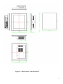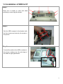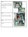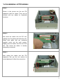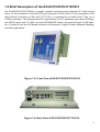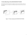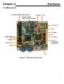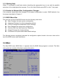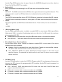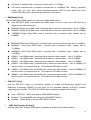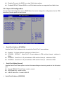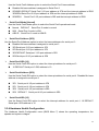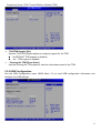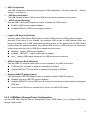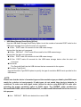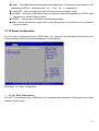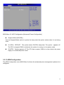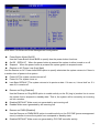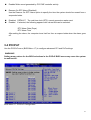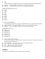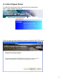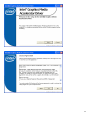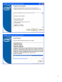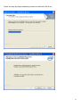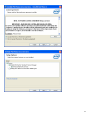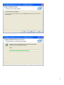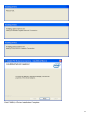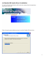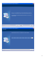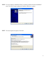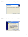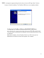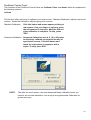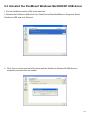
1
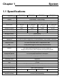
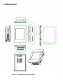
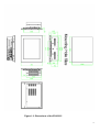
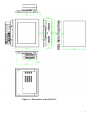
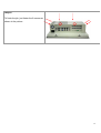
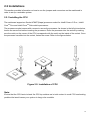
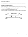
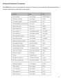
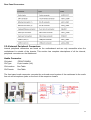
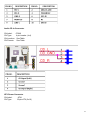
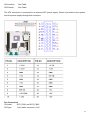
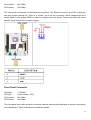
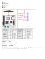
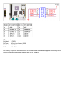
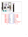
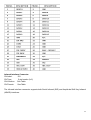
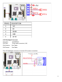
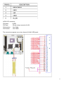
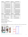
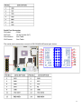
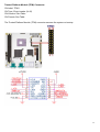
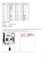
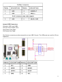
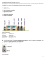
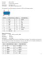
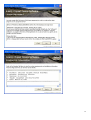
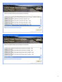
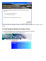
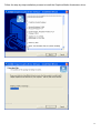
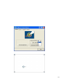
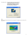
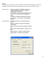
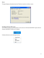
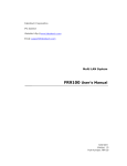
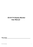
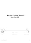
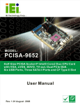
)zEX-9662 CPU Card EX93215/93515/93715/93915 Panel PC User Manual 1 Warning!___________________________________ This equipment generates, uses and can radiate radio frequency energy and if not installed and used in accordance with the instructions manual, it may cause interference to radio communications. It has been tested and found to comply with the limits for a Class A computing device pursuant to FCC Rules, which are designed to provide reasonable protection against such interference when operated in a commercial environment. Operation of this equipment in a residential area is likely to cause interference in which case the user at his own expense will be required to take whatever measures may be required to correct the interference. Electric Shock Hazard – Do not operate the machine with its back cover removed. There are dangerous high voltages inside. Disclaimer This information in this document is subject to change without notice. In no event shall TOPSCCC Technology Inc. be liable for damages of any kind, whether incidental or consequential, arising from either the use or misuse of information in this document or in any related materials. 2 Packing List Accessories (as ticked) included in this package are: □ AC power cable □ Driver & manual CD disc □ Other.___________________(please specify) Safety Precautions Follow the messages below to prevent your systems from damage: ◆ Avoid your system from static electricity on all occasions. ◆ Prevent electric shock. Don‘t touch any components of this card when the card is power-on. Always disconnect power when the system is not in use. ◆ Disconnect power when you change any hardware devices. For instance, when you connect a jumper or install any cards, a surge of power may damage the electronic components or the whole system. 3 Table of Contents______________________ Warning!…………………………………………………………………………….……..….2 Disclaimer………………………………………………………………….…………………2 Packing List…………………………………………………………………………………..3 Safety Precautions…………………………………………………………………………..3 Chapter 1 1.1 1.2 1.3 1.4 1.5 1.6 Chapter 2 Getting Started Specifications……………………………………….……………………..6 Dimensions………………………………...………………………….......7 Installation of HDD & CF……...…………………………………….…..11 Installation of PCI Addon………………………………………………..13 Brief Description…………………………………………………….……15 Panel Mounting…………………………………………………………..16 Hardware 2.1 Mainboard………………..…….……………………………………..…..17 2.2 Installations…….…………………………………….…………………...18 2.2.1 Installing CPU…….……………………...………………………….....18 2.2.2 Installing Memory………………………………………………..….....19 2.2.3 Installing the Jumpers…………………………………………….....20 2.2.4 Internal Peripheral Connectors……….…………………………....22 2.2.5 External Interface Connectors…….…………………………....37 Chapter 3 3.1 3.2 3.3 3.4 3.5 3.6 3.7 3.8 Chapter 4 BIOS Setup INTRODUCTION ..............................................................................41 MAIN ....................................................................................42 ADVANCED......................................................................................43 PCI/PNP ..................................................................... ............ 61 BOOT ........................................................................................... 62 SECURITY................................................................................ 66 CHIPSET ..................................................................................... 67 EXIT............................................................................................. 72 Installation of Drivers 4.1 Intel Chipset Driver.…………………………...…………………………75 4.2 Intel Graphics Media Accelerator Driver...………………………..78 4 4.3 Intel 82573L & 82566DM LAN Device Driver……………………….82 4.4 Realtek HD Audio Driver Installation…….…………..…………………87 4.5 Intel Active Management Technology Driver Installation………………89 Chapter 5 Touch Screen Installation 5.1 Introduction to Controller Board..…………………………..……………96 5.2 Windows 2000/XP USB Driver Installation for 5000 Boards………..….96 5.3 Uninstall the PenMount Windows Me/2000/XP USB driver…………..109 Figures Figure 1.1: EX-93215 Dimensions……………………………………..…....7 Figure 1.2: EX-93515 Dimensions…………………………………………..8 Figure 1.3: EX-93715 Dimensions………………………………………….9 Figure 1.4: EX-93915 Dimensions………………………………………….10 Figure 1.5: Front View ……………………………………………………….15 Figure 1.6: Rear View………………………………………………………...15 Figure 1.7: Panel Mounting…………………………………………………..16 Figure 2.1: Mainboard Overview………………………………………….....17 Figure 2.2 Installation of CPU………………………………………………..18 Figure 2.3 Installation of Memory Module……………………………..……19 Figure 2.4 Connector and Jumper Locations………………………..............20 Figure 5.1 Birdeye’s View of Control Board…………………………………96 5 Chapter 1 System 1.1 Specifications Specs EX-93215 EX-93515 EX-93715 EX-93915 CPU Socket P Intel® Core™ 2 Duo processor with 533/667/800MHz FSB Chipset Intel®GM965 + Intel®ICH8ME Processor Side Bus Freq. 533MHz/667MHz/800MHz FSB System Memory 2 x DDR2 DIMM Socket, Support DDR2 667/533 up to 4GB Display Size 12.1” 800x600 TFT 15” 1024x768 17” 1280x1024 19” 1280x1024 LCD TFT LCD TFT LCD TFT LCD Maximum Colors 262K 262K 16.2M 16.7M Viewing Angle (Degree) H:120/V:95 H:140/V:125 H:140/V:130 H:160/V:160 Luminance (cd/m²) 300 450 300 300 Backlight Lifetime 50,000 Hours Rating NEMA 4/IP65 certified Front Bezel Touch Screen Type 8-Wire Resistive (optional) Serial Port 3 x RS-232 (DB-9 connectors), 1x RS232/422/485 (14-pin header Connector) USB Port 4 x USB port and 4 x pin header connector Serial ATA Parts 2 x SATAII connectors with 3.0 Gbps transfer rates IDE 1 x IDE channel support 2 Ultra ATA 100/66/33 divices Extension 2 x PCI slots by Riser Card / 1x PCIe mini card slot Infrared One IrDA connector through the iTE IT8712F super I/O Supports Serial infrared (SIR), Amplitude Shift Keyed IR(ASKIR) Storage 1 x 2.5” SATA HDD or 1 x CF (Optional), 1 x Slim CD-ROM/DVD Combo Keyboard & Mouse 2 x PS/2 Keyboard and Mouse Connectors Digital I/O 8-bit digital I/O, 4 in/4 out by super I/O BIOS AMI BIOS Label Watchdog Timer Supported LAN 2 x Gigabit LAN VGA 1 x VGA Audio RealTek ALC883 with 7.1 channel HD audio Interface Power Supply 220W/ 0.8U ATX/AC or DC 16~36V (Optional) Construction and Color Steel Chassis and Beige Dimensions (WxHxD) 390 x 265 x 111 410 x 310 x 111 457 x 355 x 123 Operating Temperature 0~60℃ (32℉~140℉) Relative Humidity 5%~95% (non-condensing) 484 x 400 x 139.5 6 1.2 Dimensions Figure 1.1: Dimensions of the EX-93215 7 Figure 1.2: Dimensions of the EX-93515 8 Figure 1.3: Dimensions of the EX-93715 9 Figure 1.4: Dimensions of the EX-93915 10 1.3 Installation of HDD & CF Step 1 There are 8 screws to deal with when enclosing or removing the chassis. Step 2 Get the HDD screwed to the bracket with the four screws as shown by the arrows in the picture. Step 3 Connect the cable to the HDD as shown in the picture, making sure the red stripe of the cable is rightly positioned. 11 Step 4 Get the four screws as circled tightened to secure the HDD. As can be obviously seen, the CF Card Board is screwed to the top of the HDD. ** Option CF slot. Step 5 Connect the other end of the cable to the SATA connect as shown in the picture. Step 6 That’s how it should look after it has been installed. 12 1.4 Installation of PCI Addon Step 1 Shown in the picture are the two PCI expansion slots as circled. They can be inserted with any addon for expanded functions. Step 2 Now slide the addon into the PCI slot, making sure the golden part faces the slot. When both parts that are interfaced together come into the right contact, slightly push the addon into the rail of the slot. This shows the addon is already completely connected. Step 3 After sliding the addon into the PCI expansion slot, get the two screws as circled tightened to finish the connection. 13 Step 4 To finish the job, just fasten the 8 screws as shown in the picture. 14 1.5 Brief Description of the EX-93215/3515/3715/3915 The EX-93215/3515/3715/3915 is a rugged, compact and panel-mount industrial PC, which comes with a 12-inch (luminance of 300 cd/m²)/15-inch (luminance of 350 cd/m²)/17-inch (luminance of 300 cd/m²)/19-inch (luminance of 300 cd/m²) TFT LCD. It is powered by an Intel® Core™ Duo, up to 2.33GHz processor. The industrial panel PC also features two PCI expansion slots, three COM port, four USB 2.0 ports, one 2.5” HDD, one slim CD-ROM/DVD Combo, Universal AC power of 100~240V, etc. It is ideal for use as a PC-based controller for Automotive, Logistic Process, Materials Handling, and Kiosk applications. Figure 1.5: Front View of EX-93215/3515/3715/3915 Figure 1.6: Rear View of EX-93215/3515/3715/3915 15 1.6 Panel Mounting of the EX-93215/3515/3715/3915 The EX-93215/3515/3715/3915 panel PC is designed to be panel-mounted as shown in Figure 1.6. Just carefully place the unit through the hole and tighten the given 8 screws from the rear to secure the mounting. Figure 1.7: Panel mounting of the EX-93215/3515/3715/3915 16 Chapter 2 Hardware 2.1 Mainboard Figure 2.1: Mainboard Overview 17 2.2 Installations This section provides information on how to use the jumpers and connectors on the mainboard in order to set up a workable system. 2.2.1 Installing the CPU The mainboard supports a Socket 478MT (Napa) processor socket for Intel® CoreTM 2 Duo , Intel® CoreTM Duo and Intel® CoreTM Solo mobile processors. The processor socket comes with a screw to secure the processor. As shown in the left picture below, loosen the screw first before inserting the processor. Place the processor into the socket by making sure the notch on the corner of the CPU corresponds with the notch on the inside of the socket. Once the processor has slide into the socket, fasten the screw. Refer to the figures below. Figure 2.2: Installation of CPU Note: Ensure that the CPU heat sink and the CPU top surface are in total contact to avoid CPU overheating problem that would cause your system to hang or be unstable. 18 2.2.2 Installing the Memory The mainboard supports two DDR2 memory socket for a maximum total memory of 4GB in DDR2 memory type. Installing and Removing Memory Modules To install the DDR2 modules, locate the memory slot on the board and perform the following steps: 1. Hold the DDR2 module so that the key of the DDR2 module align with those on the memory slot. 2. Gently push the DDR2 module in an upright position until the clips of the slot close to hold the DDR2 module in place when the DDR2 module touches the bottom of the slot. 3. To remove the DDR2 module, press the clips with both hands. 4. CAUTION: The DIMM 1 socket must be installed with one DDR2 DIMM to enable the system to boot-up properly Figure 2.3: Installation of Memory Module 19 2.2.3 Installing the Jumpers Section 2.2.3 shows peripheral interface connector locations and lists all the peripheral interface connectors. Mainboard Layout Figure 2.4 shows the on-board peripheral connectors, backplane peripheral connectors and on-board jumpers. Figure 2.4: Connector and Jumper Locations 20 Peripheral Interface Connectors The Table shows a list of the peripheral interface connectors on the mainboard. Detailed descriptions of these connectors can be found in this Section. 21 Rear Panel Connectors 2.2.4 Internal Peripheral Connectors Internal peripheral connectors are found on the motherboard and are only accessible when the motherboard is outside of the chassis. This section has complete descriptions of all the internal, peripheral connectors on the Mainboard. Audio Connector CN Label: CN Type: CN Location: CN Pinouts: FRONT-PANEL1 10-pin header (2x5) See Table See Table The front panel audio connector connects the on-board sound system of the mainboard to the audio line out and microphone jacks on the front of the computer chassis. 22 Audio CD In Connector CN Label: CDIN1 CN Type: 4-pin header (1x4) CN Location: See Table CN Pinouts: See Table ATX Power Connector CN Label: ATX1 CN Type: 20-pin ATX (2x10) 23 CN Location: CN Pinouts: See Table See Table The ATX connector is connected to an external ATX power supply. Power is provided to the system, from the power supply through this connector. Fan Connectors CN Label: SYS_FAN1 and SYS_FAN2 CN Type: 3-pin wafer connector (1x3) 24 CN Location: CN Pinouts: See Table See Table The cooling fan connectors on the Mainboard provide a 12V, 500mA current to one CPU cooling fan and one system cooling fan. There is a “sense” pin in the fan connector, which transfers the fan’s sense signal to the system BIOS in order to recognize the fan speed. Please note that only some specific types of fans offer a rotation signal. Front Panel Connector CN Label: CN Type: CN Location: CN Pinouts: F_PANEL1 10-pin header (1x10) See Table See Table The front panel connector connects to several external switches and indicators to monitor and control the motherboard. These indicators and switches include: 25 ▓ Power ▓ Power button ▓ Reset button ▓ Speaker ▓ HDD Digital Input/Output Connector CN Label: DIO1 CN Type: 10-pin header (2x5) CN Location: See Table CN Pinouts: See Table The DIO connector is managed through a Super I/O chip. The DIO connector pins are user programmable. The digital IO port of Mainboard is 5V CMOS level. 26 IDE Connector CN Label: PIDE1 CN Type: 40-pin box header (2x20) CN Location: See Table CN Pinouts: See Table One primary 40-pin IDE device connector on the Mainboard motherboard supports connectivity to ATA 100/66/33 IDE devices with data transfer rates up to 100MB/s. 27 28 Infrared Interface Connector CN Label: IR1 CN Type: 5-pin header (1x5) CN Location: See Table CN Pinouts: See Table The infrared interface connector supports both Serial Infrared (SIR) and Amplitude Shift Key Infrared (ASKIR) interfaces. 29 LCD Backlight Connector CN Label: INVERTER1 CN Type: 5-pin wafer connector (1x5) CN Location: See Table CN Pinouts: See Table The LCD backlight connector is for the LCD inverter connection. 30 LVDS LCD connector CN Label: LVDS1 CN Type: 30-pin crimp connector (2x15) CN Location: See Table CN Pinouts: See Table The connector supports one or two channel 24-bit LVDS panel. 31 SATA Drive Connectors CN Label: S_ATA1 and S_ATA2 CN Type: 7-pin SATA drive connectors (1x7) CN Location: See Table CN Pinouts: See Table The two SATA drive connectors are connected to four SATA II drives. SATA II drives transfer data at speeds as high as 3.0Gbps. 32 Serial Port Connector CN Label: COM1 CN Type: 14-pin header (2x7) CN Location: See Table CN Pinouts: See Table The serial ports connectors connect to RS-232/422/485 serial port device. 33 Trusted Platform Module (TPM) Connector CN Label: TPM1 CN Type: 20-pin header (2x10) CN Location: See Table CN Pinouts: See Table The Trusted Platform Module (TPM) connector secures the system on bootup. 34 TV Out Connector CN Label: TV1 CN Type: 6-pin header (2x3) CN Location: See Table CN Pinouts: See Table The 2x3 pin TV out connector connects to a TV output by using an S-Video or RCA connector. The TV out connector makes displaying media data on a television easier. 35 Internal USB Connectors CN Label: USB1 and USB2 CN Type: 8-pin header (2x4) CN Location: See Table CN Pinouts: See Table One 2x4 pin connector provides connectivity to two USB 2.0 ports. The USB ports are used for I/O bus expansion. 36 2.2.5 External Interface Connectors The peripheral connectors on the back panel are connected to devices externally when the Mainboard is installed in a chassis. The peripheral connectors on the rear panel are: 2 x Audio jacks 1 x CRT connector 2 x RJ-45 Ethernet connectors 1 x Keyboard connector 1 x Mouse connector 3 x Serial port connectors 4 x USB 2.0 connectors Audio Connectors CN Label: AUDIO_CV1 CN Type: Audio jack CN Location: See Figure 4-18 CN Pinouts: See Figure 4-19 Line Out port (Lime): Connects a headphone or a speaker. In 4,6,8-channel configuration, the function of this port becomes Front Speaker Out. Microphone (Pink): Connects a microphone. CRT Connector 37 CN Label: CN Type: CN Location: CN Pinouts: VGA1_COM1 15-pin female connector See Figure 4-18 See Table 4-19 and Figure 4-20 The standard 15-pin VGA connector connects to a CRT or LCD display monitor. Ethernet Connectors CN Label: LAN1_USB1 and LAN2_USB2 CN Type: RJ-45 CN Location: See Table CN Pinouts: See Table The Mainboard is equipped with two built-in GbE Ethernet controllers. The controllers can connect to the LAN through two RJ-45 LAN connectors. There are two LEDs on the connector indicating the status of LAN. The pin assignments are listed in the following table: 38 The RJ-45 Ethernet connector has two status LEDs, one green and one yellow. The green LED indicates activity on the port and the yellow LED indicates the port is linked. Keyboard/Mouse Connector CN Label: KB_MS1 CN Type: PS/2 connector CN Location: See Figure 4-18 CN Pinouts: See Table 4-22 The Mainboard keyboard and mouse connectors are standard PS/2 connectors. 39 Serial Port Connectors CN Label: VGA1_COM1 and COM_C1 CN Type: DB-9 CN Location: See Table CN Pinouts: See Table The serial ports can be connected to a serial communications device directly. USB Connector CN Label: LAN1_USB1 and LAN2_USB2 CN Type: USB port CN Location: See Figure 4-18 CN Pinouts: See Table 4-24 USB devices can be connected directly to the USB connectors on the rear panel. 40 Chapter 3 BIOS Setup 3.1 Introduction A licensed copy of AMI BIOS is preprogrammed into the ROM BIOS. The BIOS setup program allows users to modify the basic system configuration. This chapter describes how to access the BIOS setup program and the configuration options that may be changed. 3.1.1 Starting Setup The AMI BIOS is activated when the computer is turned on. The setup program can be activated in one of two ways. 1. Press the DELETE key as soon as the system is turned on or 2. Press the DELETE key when the “Press Del to enter SETUP” message appears on the screen. If the message disappears before the DELETE key is pressed, restart the computer and try again. 3.1.2 Using Setup Use the arrow keys to highlight items, press ENTER to select, use the PageUp and PageDown keys to change entries, press F1 for help and press ESC to quit. Navigation keys are shown in. 41 3.1.3 Getting Help When F1 is pressed a small help window describing the appropriate keys to use and the possible selections for the highlighted item appears. To exit the Help Window press ESC or the F1 key again. 3.1.4 Unable to Reboot After Configuration Changes If the computer cannot boot after changes to the system configuration is made, CMOS defaults. Use the jumper described in Chapter 5. 3.1.5 BIOS Menu Bar The menu bar on top of the BIOS screen has the following main items: Main Changes the basic system configuration. Advanced Changes the advanced system settings. PCIPnP Changes the advanced PCI/PnP Settings Boot Changes the system boot configuration. Security Sets User and Supervisor Passwords. Chipset Changes the chipset settings. Exit Selects exit options and loads default settings The following sections completely describe the configuration options found in the menu items at the top of the BIOS screen and listed above. 3.2 Main The Main BIOS menu (BIOS Menu 1) appears when the BIOS Setup program is entered. The Main menu gives an overview of the basic system information. 42 ¾ System Overview The System Overview lists a brief summary of different system components. The fields in System Overview cannot be changed. The items shown in the system overview include: AMI BIOS: Displays auto-detected BIOS information Version: Current BIOS version Build Date: Date the current BIOS version was made ID: Installed BIOS ID Processor: Displays auto-detected CPU specifications Type: Names the currently installed processor Speed: Lists the processor speed Count: The number of CPUs on the motherboard System Memory: Displays the auto-detected system memory. Size: Lists memory size The System Overview field also has two user configurable fields: ¾ System Time [xx:xx:xx] Use the System Time option to set the system time. Manually enter the hours, minutes and seconds. ¾ System Date [xx/xx/xx] Use the System Date option to set the system date. Manually enter the day, month and year. 3.3 Advanced Use the Advanced menu (BIOS Menu 2) to configure the CPU and peripheral devices through the following sub-menus: WARNING! Setting the wrong values in the sections below may cause the system to malfunction. Make sure that the settings made are compatible with the hardware. CPU Configuration IDE Configuration Super IO Configuration Hardware Health Configuration Intel AMT Configuration Intel Robson Configuration Remote Access Configuration Trusted Computing USB Configuration 43 Power Configuration 3.3.1 CPU Configuration Use the CPU Configuration menu (BIOS Menu 3) to view detailed CPU specifications and configure the CPU. The CPU Configuration menu (BIOS Menu 3) lists the following CPU details: Manufacturer: Lists the name of the CPU manufacturer Brand String: Lists the brand name of the CPU being used Frequency: Lists the CPU processing speed 44 FSB Speed: Lists the FSB speed Cache L1: Lists the CPU L1 cache size Cache L2: Lists the CPU L2 cache size 3.3.2 IDE Configuration Use the IDE Configuration menu (BIOS Menu 4) to change and/or set the configuration of the IDE devices installed in the system. ¾ ATA/IDE Configurations [Compatible] Use the ATA/IDE Configurations option to configure the ATA/IDE controller. ¾ Disabled Disables the on-board ATA/IDE controller. ¾ Compatible DEFAULT Configures the on-board ATA/IDE controller to be in compatible mode. In this mode, a SATA channel will replace one of the IDE channels. This mode supports up to 4 storage devices. ¾ Enhanced Configures the on-board ATA/IDE controller to be in Enhanced mode. In this mode, IDE channels and SATA channels are separated. This mode supports up to 6 storage devices. Some legacy OS do not support this mode. ¾ Legacy IDE Channels [SATA Pri, PATA Sec] 45 ¾ SATA Only SATA Pri., PATA Sec DEFAULT PATA Only IDE Master and IDE Slave When entering setup, BIOS auto detects the presence of IDE devices. BIOS displays the status of the auto detected IDE devices. The following IDE devices are detected and are shown in the IDE Configuration menu: Primary IDE Master Primary IDE Slave Secondary IDE Master Secondary IDE Slave Third IDE Master Third IDE Slave Fourth IDE Master Fourth IDE Slave The IDE Configuration menu (BIOS Menu 4) allows changes to the configurations for the IDE devices installed in the system. If an IDE device is detected, and one of the above listed four BIOS configuration options are selected, the IDE configuration options shown in Section 6.3.2.1 appear. 3.3.2.1 IDE Master, IDE Slave Use the IDE Master and IDE Slave configuration menu to view both primary and secondary IDE device details and configure the IDE devices connected to the system. ¾ Type [Auto] 46 Use the Type BIOS option select the type of device the AMIBIOS attempts to boot from after the Power-On Self-Test (POST) is complete. ¾ Not Installed BIOS is prevented from searching for an IDE disk drive on the specified channel. ¾ Auto DEFAULT The BIOS auto detects the IDE disk drive type attached to the specified channel. This setting should be used if an IDE hard disk drive is attached to the specified channel. ¾ CD/DVD The CD/DVD option specifies that an IDE CD-ROM drive is attached to the specified IDE channel. The BIOS does not attempt to search for other types of IDE disk drives on the specified channel. ¾ ARMD This option specifies an ATAPI Removable Media Device. These include, but are not limited to: ZIP LS-120 ¾ LBA/Large Mode [Auto] Use the LBA/Large Mode option to disable or enable BIOS to auto detects LBA (Logical Block Addressing). LBA is a method of addressing data on a disk drive. In LBA mode, the maximum drive capacity is 137 GB. Disabled BIOS is prevented from using the LBA mode control on the specified channel. Auto DEFAULT BIOS auto detects the LBA mode control on the specified channel. ¾ Block (Multi Sector Transfer) [Auto] Use the Block (Multi Sector Transfer) to disable or enable BIOS to auto detect if the device supports multi-sector transfers. Disabled BIOS is prevented from using Multi-Sector Transfer on the specified channel. The data to and from the device occurs one sector at a time. Auto DEFAULT BIOS auto detects Multi-Sector Transfer support on the drive on the specified channel. If supported the data transfer to and from the device occurs multiple sectors at a time. ¾ PIO Mode [Auto] Use the PIO Mode option to select the IDE PIO (Programmable I/O) mode program timing cycles between the IDE drive and the programmable IDE controller. As the PIO mode increases, the cycle time decreases. Auto DEFAULT BIOS auto detects the PIO mode. Use this value if the IDE disk drive support cannot be determined. PIO mode 0 selected with a maximum transfer rate of 3.3MBps PIO mode 1 selected with a maximum transfer rate of 5.2MBps PIO mode 2 selected with a maximum transfer rate of 8.3MBps 47 ¾ DMA Mode [Auto] Use the DMA Mode BIOS selection to adjust the DMA mode options. Auto DEFAULT BIOS auto detects the DMA mode. Use this value if the IDE disk drive support cannot be determined. SWDMA0 Single Word DMA mode 0 selected with a maximum data transfer rate of 2.1MBps SWDMA1 Single Word DMA mode 1 selected with a maximum data transfer rate of 4.2MBps SWDMA2 Single Word DMA mode 2 selected with a maximum data transfer rate of 8.3MBps ¾ MWDMA0 Multi Word DMA mode 0 selected with a maximum data transfer rate of 4.2MBps MWDMA1 Multi Word DMA mode 1 selected with a maximum data transfer rate of 13.3MBps MWDMA2 Multi Word DMA mode 2 selected with a maximum data transfer rate of 16.6MBps UDMA1 Ultra DMA mode 0 selected with a maximum data transfer rate of 16.6MBps UDMA1 Ultra DMA mode 1 selected with a maximum data transfer rate of 25MBps UDMA2 Ultra DMA mode 2 selected with a maximum data transfer rate of 33.3MBps UDMA3 Ultra DMA mode 3 selected with a maximum data transfer rate of 44MBps (To use this mode, it is required that an 80-conductor ATA cable is used.) UDMA4 Ultra DMA mode 4 selected with a maximum data transfer rate of 66.6MBps (To use this mode, it is required that an 80-conductor ATA cable is used.) UDMA5 Ultra DMA mode 5 selected with a maximum data transfer rate of 99.9MBps (To use this mode, it is required that an 80-conductor ATA cable is used.) S.M.A.R.T [Auto] Use the S.M.A.R.T option to auto-detect, disable or enable Self-Monitoring Analysis and Reporting Technology (SMART) on the drive on the specified channel. S.M.A.R.T predicts impending drive failures. The S.M.A.R.T BIOS option enables or disables this function. ¾ PIO mode 3 selected with a maximum transfer rate of 11.1MBps PIO mode 4 selected with a maximum transfer rate of 16.6MBps (This setting generally works with all hard disk drives manufactured after 1999. For other disk drives, such as IDE CD-ROM drives, check the specifications of the drive.) Auto DEFAULT BIOS auto detects HDD SMART support. Disabled Prevents BIOS from using the HDD SMART feature. Enabled Allows BIOS to use the HDD SMART feature 32Bit Data Transfer [Enabled] Use the 32Bit Data Transfer BIOS option to enables or disable 32-bit data transfers. 48 Disabled Prevents the BIOS from using 32-bit data transfers. Enabled DEFAULT Allows BIOS to use 32-bit data transfers on supported hard disk drives. 3.3.3 Super IO Configuration Use the Super IO Configuration menu (BIOS Menu 6) to set or change the configurations for the FDD controllers, parallel ports and serial ports. ¾ Serial Port1 Address [3F8/IRQ4] Use the Serial Port1 Address option to select the Serial Port 1 base address. Disabled 3F8/IRQ4 IRQ4 3E8/IRQ4 2E8/IRQ3 No base address is assigned to Serial Port 1 DEFAULT Serial Port 1 I/O port address is 3F8 and the interrupt address is Serial Port 1 I/O port address is 3E8 and the interrupt address is IRQ4 Serial Port 1 I/O port address is 2E8 and the interrupt address is IRQ3 ¾ Serial Port1 Mode [Normal] Use the Serial Port1 Mode option to select the transmitting and receiving mode for the first serial port. Normal DEFAULT Serial Port 1 mode is normal IrDA Serial Port 1 mode is IrDA ASK IR Serial Port 1 mode is ASK IR ¾ Serial Port2 Address [2F8/IRQ3] 49 Use the Serial Port2 Address option to select the Serial Port 2 base address. Disabled No base address is assigned to Serial Port 2 2F8/IRQ3 DEFAULT Serial Port 2 I/O port address is 3F8 and the interrupt address is IRQ3 3E8/IRQ4 Serial Port 2 I/O port address is 3E8 and the interrupt address is IRQ4 2E8/IRQ3 Serial Port 2 I/O port address is 2E8 and the interrupt address is IRQ3 ¾ Serial Port2 Mode [Normal] Use the Serial Port2 Mode option to select the Serial Port2 operational mode. Normal DEFAULT Serial Port 2 mode is normal IrDA Serial Port 2 mode is IrDA ASK IR Serial Port 2 mode is ASK IR ¾ Serial Port3 Address [3E8] Use the Serial Port3 Address option to select the base addresses for serial port 3 Disabled No base address is assigned to serial port 3 3F8 Serial port 3 I/O port address is 3F8 2F8 Serial port 3 I/O port address is 2F8 3E8 DEFAULT Serial port 3 I/O port address is 3E8 2E8 Serial port 3 I/O port address is 2E8 ¾ Serial Port3 IRQ [10] Use the Serial Port3 IRQ option to select the interrupt address for serial port 3. 10 DEFAULT Serial port 3 IRQ address is 10 ¾ Serial Port4 Address [2E8] Use the Serial Port4 IRQ option to select the interrupt address for serial port 4. Disabled No base address is assigned to serial port 3 ¾ 3F8 Serial port 4 I/O port address is 3F8 2F8 Serial port 4 I/O port address is 2F8 3E8 Serial port 4 I/O port address is 3E8 2E8 DEFAULT Serial port 4 I/O port address is 2E8 Serial Port4 IRQ [10] Use the Serial Port4 IRQ option to select the interrupt address for serial port 4. 10 DEFAULT Serial port 4 IRQ address is 10 3.3.4 Hardware Health Configuration The Hardware Health Configuration menu (BIOS Menu 7) shows the operating temperature, fan speeds and system voltages. 50 The following system parameters and values are shown. The system parameters that are monitored are: ¾ System Temperatures: The following system temperatures are monitored CPU Temperature PWM Temperature System Temperature ¾ Fan Speeds: The CPU cooling fan speed is monitored. Fan1 Speed Fan2 Speed ¾ Voltages: The following system voltages are monitored CPU Core +1.8V +3.30V +5.00V +12.0V +1.05V +1.5V +1.25V VBAT 3.3.5 Intel AMT Configuration The Intel AMT Configuration menu (BIOS Menu 8) configures the IntelR Active Management Technology (AMT) options. 51 ¾ Intel AMT Support [Disabled] Use the Intel AMT Support option to enable or disable the Intel AMT support. Disabled DEFAULT The IntelR AMT function is disabled. Enabled The IntelR AMT function is enabled. 3.3.6 Intel Robson Configuration The Intel Robson Configuration menu (BIOS Menu 9) allows the IntelR Robson Technology option to be configured. 52 ¾ Intel Robson [Disabled] Use the Intel Robson BIOS option to enable or disable the IntelR Robson Technology feature. IntelR Robson, IntelR Turbo Memory, is a technology introduced by IntelR to boost a computer startup process. Disabled DEFAULT Disables the IntelR Robson feature Enabled Enables the IntelR Robson feature 3.3.7 Remote Access Configuration Use the Remote Access Configuration menu (BIOS Menu 10) to configure remote access parameters. The Remote Access Configuration is an AMIBIOS feature and allows a remote host running a terminal program to display and configure the BIOS settings. ¾ Remote Access [Disabled] Use the Remote Access option to enable or disable access to the remote functionalities of the system. Disabled DEFAULT Remote access is disabled. Enabled Remote access configuration options shown below appear: Serial Port Number Serial Port Mode Redirection after BIOS POST Terminal Type ¾ Serial Port Number [COM1] 53 Use the Serial Port Number option allows users to select the serial port used for remote access. COM1 DEFAULT System is remotely accessed through COM1 COM2 System is remotely accessed through COM2 COM3 System is remotely accessed through COM3 COM4 System is remotely accessed through COM4 COM5 System is remotely accessed through COM5 NOTE: Make sure the selected COM port is enabled through the Super I/O configuration menu. Base Address, IRQ [3F8h,4] ¾ The Base Address, IRQ option cannot be configured and only shows the interrupt address of the serial port listed above. ¾ Serial Port Mode [115200 8,n,1] Use the Serial Port Mode option to select baud rate through which the console redirection is made. The following configuration options are available 115200 8,n,1 DEFAULT 57600 8,n,1 38400 8,n,1 19200 8,n,1 09600 8,n,1 NOTE: Identical baud rate setting musts be set on the host (a management computer running a terminal software) and the slave ¾ Redirection After BIOS POST [Always] Use the Redirection After BIOS POST option to specify when console redirection should occur. Disabled The console is not redirected after POST Boot Loader Redirection is active during POST and during Boot Loader Always DEFAULT Redirection is always active (Some OSes may not work if set to Always) ¾ Terminal Type [ANSI] Use the Terminal Type BIOS option to specify the remote terminal type. ANSI DEFAULT The target terminal type is ANSI VT100 The target terminal type is VT100 VT-UTF8 The target terminal type is VT-UTF8 3.3.8 Trusted Computing Use the Trusted Computing menu (BIOS Menu 11) to configure settings related to the Trusted 54 Computing Group (TCG) Trusted Platform Module (TPM). ¾ TCG/TPM Support [No] Use the TCG/TPM Support option to configure support for the TPM. No DEFAULT TPM support is disabled. Yes TPM support is enabled. ¾ Clearing the TPM [Press Enter] Use the Clearing the TPM option to clear the information stored in the TPM. 3.3.9 USB Configuration Use the USB Configuration menu (BIOS Menu 12) to read USB configuration information and configure the USB settings. 55 ¾ USB Configuration The USB Configuration field shows the system USB configuration. The items listed are: Version: x.xxxxx.xxxxx Module ¾ USB Devices Enabled The USB Devices Enabled field lists the USB devices that are enabled on the system ¾ USB Function [Enabled] Use the USB Function BIOS option to enable or disable the USB function. Disabled USB function support disabled Enabled DEFAULT USB function support enabled ¾ Legacy USB Support [Enabled] Use the Legacy USB Support BIOS option to enable USB mouse and USB keyboard support. Normally if this option is not enabled, any attached USB mouse or USB keyboard does not become available until a USB compatible operating system is fully booted with all USB drivers loaded. When this option is enabled, any attached USB mouse or USB keyboard can control the system even when there is no USB driver loaded onto the system. Disabled Legacy USB support disabled Enabled DEFAULT Legacy USB support enabled Auto Legacy USB support disabled if no USB devices are connected ¾ USB2.0 Controller Mode [HiSpeed] Use the USB2.0 Controller Mode option to set the speed of the USB2.0 controller. FullSpeed The controller is capable of operating at 12Mb/s HiSpeed DEFAULT The controller is capable of operating at 480Mb/s ¾ Hotplug USB FDD Support [Auto] Use the Hotplug USB FDD Support option to enable or disable USB FDD support. Disabled Hot-plug USB FDD support disabled. Enabled DEFAULT A virtual FDD drive is created and will be associated with the hotplugged FDD later. Auto A virtual FDD drive is created only if there is no USB FDD present. 3.3.9.1 USB Mass Storage Device Configuration Use the USB Mass Storage Device Configuration menu (BIOS Menu 13) to configure USB mass storage class devices. 56 ¾ USB Mass Storage Reset Delay [20 Sec] Use the USB Mass Storage Reset Delay option to set the number of seconds POST waits for the USB mass storage device after the start unit command. 10 Sec POST waits 10 seconds for the USB mass storage device after the start unit command. 20 Sec DEFAULT POST waits 20 seconds for the USB mass storage device after the start unit command. 30 Sec POST waits 30 seconds for the USB mass storage 40 Sec POST waits 40 seconds for the USB mass storage device after the start unit command. Device ## The Device## field lists the USB devices that are connected to the system. Emulation Type [Auto] Use the Emulation Type BIOS option to specify the type of emulation BIOS has to provide for the USB device. NOTE: Please note that the device’s formatted type and the emulation type provided by the BIOS must match for a device to boot properly. If both types do not match then device’s behavior is undefined. To make sure both types match, format the device using BIOS INT13h calls after selecting the proper emulation option in BIOS setup. The FORMAT utility provided by MicrosoftR MS-DOSR, MicrosoftR WindowsR 95, and MicrosoftR WindowsR 98 can be used for this purpose. Auto DEFAULT BIOS auto-detects the current USB. 57 Floppy The USB device will be emulated as a floppy drive. The device can be either A: or B: esponding to INT13h calls that return DL = 0 or DL = 1 respectively. Forced FDD Allows a hard disk image to be connected as a floppy image Hard Disk Allows the USB device to be emulated as hard disk responding to INT13h calls that return DL values of 80h or above. CDROM Assumes the CD-ROM is formatted as bootable media. All the devices that support block sizes greater than 512 bytes can only be booted using this option. 3.3.10 Power Configuration Use the Power Configuration menu (BIOS Menu 14) configures the Advanced Configuration and Power Interface (ACPI) and Power Management (APM) options. BIOS Menu 14: Power Configuration ¾ 3.3.10.1 ACPI Configuration The ACPI Configuration menu (BIOS Menu 8) configures the Advanced Configuration and Power Interface (ACPI) option. 58 BIOS Menu 15: ACPI Configuration [Advanced\ Power Configuration] Suspend Mode [S1(POS)] Use the Suspend Mode option to specify the sleep state the system enters when it is not being used. S1 (POS) DEFAULT The system enters S1(POS) sleep state. The system appears off. The CPU is stopped; RAM is refreshed; the system is running in a low power mode. S3 (STR) System appears off. The CPU has no power; RAM is in slow refresh; the power supply is in a reduced power mode. 3.3.11 APM Configuration The APM Configuration menu (BIOS Menu 9) allows the advanced power management options to be configured. 59 BIOS Menu 16:Advanced Power Management Configuration Power Button Mode [On/Off] Use the Power Button Mode BIOS to specify how the power button functions. On/Off DEFAULT When the power button is pressed the system is either turned on or off Suspend When the power button is pressed the system goes into suspend mode Restore on AC Power Loss [Last State] Use the Restore on AC Power Loss BIOS option to specify what state the system returns to if there is a sudden loss of power to the system. Power Off The system remains turned off Power On The system turns on Last State DEFAULT The system returns to its previous state. If it was on, it turns itself on. If it was off, it remains off. Resume on Ring [Disabled] Use the Resume on Ring BIOS option to enable activity on the RI (ring in) modem line to rouse the system from a suspend or standby state. That is, the system will be roused by an incoming call on a modem. Disabled DEFAULT Wake event not generated by an incoming call Enabled Wake event generated by an incoming call Resume on PME# [Disabled] Use the Resume on PME# BIOS option to enable activity on the PCI PME (power management event) controller to rouse the system from a suspend or standby state. Disabled DEFAULT Wake event not generated by PCI PME controller activity 60 Enabled Wake event generated by PCI PME controller activity Resume On RTC Alarm [Disabled] Use the Resume On RTC Alarm option to specify the time the system should be roused from a suspended state. Disabled DEFAULT The real time clock (RTC) cannot generate a wake event Enabled If selected, the following appears with values that can be selected: RTC Alarm Date (Days) RTC Alarm Time After setting the alarm, the computer turns itself on from a suspend state when the alarm goes off. 3.4 PCI/PnP Use the PCI/PnP menu (BIOS Menu 17) to configure advanced PCI and PnP settings. WARNING! Setting wrong values for the BIOS selections in the PCIPnP BIOS menu may cause the system to malfunction. BIOS Menu 17: PCI/PnP Configuration 61 IRQ# Use the IRQ# address to specify what IRQs can be assigned to a particular peripheral device. Available The specified IRQ is available to be used by PCI/PnP devices Reserved The specified IRQ is reserved for use by Legacy ISA devices Available IRQ addresses options are: IRQ3 IRQ4 IRQ5 IRQ7 IRQ9 IRQ10 IRQ 11 IRQ 14 IRQ 15 DMA Channel# [Available] Use the DMA Channel# option to assign a specific DMA channel to a particular PCI/PnP device. Available DEFAULT The specified DMA is available to be used by PCI/PnP devices Reserved The specified DMA is reserved for use by Legacy ISA devices Available DMA Channels are: DM Channel 0 DM Channel 1 DM Channel 3 DM Channel 5 DM Channel 6 DM Channel 7 Reserved Memory Size [Disabled] Use the Reserved Memory Size BIOS option to specify the amount of memory that should be reserved for legacy ISA devices. Disabled DEFAULT No memory block reserved for legacy ISA devices 16K 16KB reserved for legacy ISA devices 32K 32KB reserved for legacy ISA devices 64K 54KB reserved for legacy ISA devices 3.5 Boot Use the Boot menu (BIOS Menu 18) to configure system boot options. 62 BIOS Menu 18: Boot 3.5.1 Boot Settings Configuration Use the Boot Settings Configuration menu (BIOS Menu 19) to configure advanced system boot options. BIOS Menu 19: Boot Settings Configuration Quick Boot [Enabled] Use the Quick Boot BIOS option to make the computer speed up the boot process. Disabled No POST procedures are skipped Enabled DEFAULT Some POST procedures are skipped to decrease the system boot time 63 Quiet Boot [Disabled] Use the Quiet Boot BIOS option to select the screen display when the system boots. Disabled DEFAULT Normal POST messages displayed Enabled OEM Logo displayed instead of POST messages AddOn ROM Display Mode [Force BIOS] Use the AddOn ROM Display Mode option to allow add-on ROM (read-only memory) messages to be displayed. Force BIOS DEFAULT The system forces third party BIOS to display during system boot. Keep Current The system displays normal information during system boot. Bootup Num-Lock [On] Use the Bootup Num-Lock BIOS option to specify if the number lock setting must be modified during boot up. Off Does not enable the keyboard Number Lock automatically. To use the 10-keys on the keyboard, press the Number Lock key located on the upper left-hand corner of the 10-key pad. The Number Lock LED on the keyboard lights up when the Number Lock is engaged. On DEFAULT Allows the Number Lock on the keyboard to be enabled automatically when the computer system boots up. This allows the immediate use of the 10-key numeric keypad located on the right side of the keyboard. To confirm this, the Number Lock LED light on the keyboard is lit. Boot From LAN Support (82573L) [Disabled] Use the BOOT From LAN Support (82573L) option to enable the IntelR 82573L PCIe GbE controller to boot the system. Disabled DEFAULT Cannot be booted from a remote system through the IntelR 82573L PCIe GbE controller Enabled Can be booted from a remote system through the IntelR 82573L PCIe GbE controller 3.5.2 Boot Device Priority Use the Boot Device Priority menu (BIOS Menu 20) to specify the boot sequence from the available devices. Possible boot devices may include: USB HDD CD/DVD 64 BIOS Menu 20: Boot Device Priority Settings 3.5.3 Removable Drives Use the Removable Drives menu (BIOS Menu 21) to specify the boot sequence of the available USB devices. When the menu is opened, the USB devices connected to the system are listed as shown below: 1st Drive [1st USB] 2nd Drive [2nd USB] 65 NOTE: Only the drives connected to the system are shown. For example, if only one USB device is connected only “1st Drive” is listed. The boot sequence from the available devices is selected. If the “1st Drive” option is selected a list of available USB devices is shown. Select the first USB device the system boots from. If the “1st Drive” is not used for booting this option may be disabled. BIOS Menu 21: Removable Drives 3.6 Security Use the Security menu (BIOS Menu 22) to set system and user passwords. 66 BIOS Menu 22: Security Change Supervisor Password Use the Change Supervisor Password to set or change a supervisor password. The default for this option is Not Installed. If a supervisor password must be installed, select this field and enter the password. After the password has been added, Install appears next to Change Supervisor Password. Change User Password Use the Change User Password to set or change a user password. The default for this option is Not Installed. If a user password must be installed, select this field and enter the password. After the password has been added, Install appears next to Change User Password. Clear User Password Use the Clear User Password to clear a user’s password. The default for this option is Not Installed. If a user password must be cleared, use this option. 3.7 Chipset Use the Chipset menu to access the NorthBridge, SouthBridge and ME Subsystem configuration menus. WARNING! Setting the wrong values for the Chipset BIOS selections in the Chipset BIOS menu may cause the system to malfunction. 3.7.1 NorthBridge Configuration Use the Northbridge Chipset Configuration menu (BIOS Menu 23) to configure the Northbridge chipset. 67 BIOS Menu 23:Northbridge Chipset Configuration Memory Remap Feature [Enabled] Use the Memory Remap Feature option to allow the overlapped PCI memory above the total physical memory to be remapped. Enabled DEFAULT Overlapped PCI memory can be remapped Disabled Overlapped PCI memory cannot be remapped Memory Hole [Disabled] Use the Memory Hole option to reserve memory space between 15MB and 16MB for ISA expansion cards that require a specified area of memory to work properly. If an older ISA expansion card is used, please refer to the documentation that came with the card to see if it is necessary to reserve the space. Disabled DEFAULT Memory is not reserved for ISA expansion cards 15MB – 16MB Between 15MB and 16MB of memory is reserved for ISA expansion cards Boots Graphics Adapter Priority [IGD] Use the Boots Graphics Adapter Priority option to select the graphics controller used as the primary boot device. Select either an integrated graphics controller (IGD) or a combination of PCI graphics controller, a PCI express (PEG) controller or an IGD. Configuration options are listed below: IGD DEFAULT PCI/IGD Internal Graphics Mode Select [Enable, 8MB] 68 Use the Internal Graphic Mode Select option to specify the amount of system memory that can be used by the Internal graphics device. Disable Enable, 1MB 1MB of memory used by internal graphics device Enable, 8MB DEFAULT 8MB of memory used by internal graphics device 3.7.1 Video Function Configuration Use the Video Function Configuration menu to configure the video device connected to the system. Boot Display Device [Auto] Use the Boot Display Device option to select the display device used by the system when it boots. Configuration options are listed below. Auto DEFAULT CRT TV LFP Flat Panel Type [1024x768 18b] Use the Flat Panel Type option to select the type of flat panel connected to the system. Configuration options are listed below. 640x480 18b 800x600 18b 1024x768 18b 1024x768 24b 1280x1024 48b 1600x1200 48b TV Standard [VBIOS-Default] Use the TV Standard option to select the standard of the television connected to the system. The configuration options are listed below. VBIOS-Default DEFAULT NTSC PAL SECAM SMPTE240M ITU-R television SMPTE295M SMPTE296M EIA-770.2 EIA-770.3 69 3.7.2 Southbridge Configuration The Southbridge Configuration menu (BIOS Menu 24) allows the Southbridge chipset to be configured. BIOS Menu 24:Southbridge Chipset Configuration HDA Controller [Enabled] Use the HDA Controller option to enable the Southbridge high definition audio controller. If the HDA device has been connected to the system, this option should be enabled. Disabled Southbridge HDA controller is disabled Enabled DEFAULT Southbridge HDA controller is enabled ASF Support [Enabled] Use the ASF Support BIOS option to control the system’s ability to connect to a remote management server. Disabled The system will not communicate with a remote management server. Enabled DEFAULT The Alert Standard Format (ASF) controller is activated and can communicate with a remote management server. 3.7.3 ME Subsystem Configuration The ME Subsystem Configuration menu (BIOS Menu 24) allows the AMT subsystem (Management Engine, ME) and Host Embedded Controller Interface (HECI) driver options to be configured. 70 BIOS Menu 25: Me Subsystem Configuration BootBlock HECI Message [Enabled] Use the BootBlock HECI Message option to enable or disable HECI message when booting up the system. Disabled The HECI message is disabled when booting up the system. Enabled DEFAULT The HECI message is enabled when booting up the system. HECI Message [Enabled] Use the HECI Message BIOS option to enable or disable HECI message. Disabled The HECI message disabled. Enabled DEFAULT The HECI message enabled. End Of Post S5 HECI Message [Enabled] Use the End Of Post S5 HECI Message option to enable or disable HECI message when the system is in the off (S5) state. Disabled The HECI message is disabled when the system is off. Enabled DEFAULT The HECI message enabled when the system is off. ME-HECI [Enabled] The ME-HECI option is enabled by default and can not be changed. ME-IDER [Disabled] Use the ME-IDER option to enable or disable the IDE-Redirection (IDE-R) function on an AMT-capable system. Disabled DEFAULT The IDE-R function is disabled. Enabled The IDE-R function allows an AMT-capable client system to access IDE 71 devices and load OS from a management system. When an IDE-R session is established, the virtual drives are shown in the system. ME-KT [Disabled] Use the ME-KT option to enable or disable the Keyboard and Text redirection (KT) function on an AMT-capable system. KT is also known as Serial-Over-Lan (SOL). Disabled DEFAULT The KT function of the ME is disabled. Enabled The KT function allows a management system to control an IntelR AMT client system remotely. The keyboard interface of a managed client system, such as BIOS menu, is displayed through the management system. 3.8 Exit Use the Exit menu (BIOS Menu 26) to load default BIOS values, optimal failsafe values and to save configuration changes. BIOS Menu 26: Exit Save Changes and Exit Use the Save Changes and Exit option to save the changes made to the BIOS options and to exit the BIOS configuration setup program. Discard Changes and Exit Use the Discard Changes and Exit option to exit the BIOS configuration setup program without saving the changes made to the system. Discard Changes Use the Discard Changes option to discard the changes and remain in the BIOS configuration setup program. Load Optimal Defaults 72 Use the Load Optimal Defaults option to load the optimal default values for each of the parameters on the Setup menus. F9 key can be used for this operation. Load Failsafe Defaults Use the Load Failsafe Defaults option to load failsafe default values for each of the parameters on the Setup menus. F8 key can be used for this operation. 73 Chapter 4 Installation of Drivers This chapter describes the installation procedures for software and drivers under the windows XP. The software and drivers are included with the motherboard. The contents include Intel chipset driver VGA driver LAN drivers Audio driver iAMT Drvier Installation instructions are given below. Important Note: After installing your Windows operating system (Windows XP), you must install first the Intel Chipset Software Installation Utility before proceeding with the installation of drivers. I 74 4.1 Intel Chipset Driver To install the Intel chipset driver, please follow the steps below. Step 1: Select Chipset from the list Follow the step-by-step installation process to install the LMS_SQL driver. 75 76 77 Click Finish, When the installation process is complete, the Setup Complete screen appears. See as picture. 4.2 Intel Graphics Media Accelerator Driver To install the VGA drivers, follow the steps below to proceed with the installation. 1. Click Intel(R) GM965 Chipset Family Graphics Driver. 78 Follow the step-by-step installation process to install the Graphics Media Accelerator driver. 79 80 81 Click FINISH; A Driver Installation Complete. 4.3 Intel 82573L & 82566DM LAN Device Driver To install the Intel R 82573L & 82566DM Gigabit LAN connect device driver, please follow the steps below. Select LAN from the list 82 Follow the step-by-step installation process to install the LAN driver. 83 84 85 Click FINISH; A Driver Installation Complete. 86 4.4 Realtek HD Audio Driver Installation To install the Realtek High Definition (HD) Audio driver, please follow the steps below. Select Audio from the list Follow the step-by-step installation process to install the Realtek HD Audio driver. 87 88 Click FINISH; A Driver Installation Complete. 4.5 Intel Active Management Technology Driver Installation To install the Intel Active Management Technology (IAMT) driver, please follow the steps below: 4.6.1 Select iAMTand Utilities (LMS_SQL) from the list Follow the step-by-step installation process to install the LMS_SQL driver. 89 90 91 Click Finish to complete the setup process. 4.6.2 Select iAMTand Utilities (HECI) from the list 92 Follow the step-by-step installation process to install the LMS_SQL driver. 93 94 Click Finish to complete the setup process. 95 Chapter 5 Touch Screen Installation This chapter describes how to install drivers and other software that will allow your PenMount 5000 Controller Board (USB) to work with different operating systems. NOTE: PenMount USB drivers support up to 15 USB controllers. 5.1 Introduction to Touch Screen Controller Board The control board is configured for use with the USB interface. It connects to the touch screen, power supply and computer system’s USB port, and supports 4-, 5- and 8-wire touch screens. The control board has some advanced functions, such as PnP and non-PnP mode adjustable baud rate, thus making easy for customers to select different touch screens without changing the control board. The size of the board is 25 by 60mm, and it has two connectors and one dipswitch on-board. Figure 5.1: Bird’s Eye View of Control Board 5.2 Windows Me/2000/XP USB Driver Installation for 5000 Boards Before installing the Windows Me/2000/XP USB driver software, you must have the Windows Me/2000/XP system installed and running on your computer. You must also have one of the following PenMount USB controller boards installed: 5184 or 51A5. Contents of the PenMount Windows Me/2000/XP USB driver folder are listed below. Setup.exe PenMount 98.inf PenMount.inf Pm_lower.sys Pm_upper.sys If you have an older version of the PenMount Windows Me/2000/XP USB driver installed in your 96 system, please remove it first. Follow the steps below to install the PenMount Windows Me/2000/XP USB driver. 5.2.1 Insert the EXPERT product cd install setup.exe. the screen below would appear. Click touch panel driver IMPORTANT! Before installing the driver software you must plug the board into a USB port. 97 5.2.2 The screen displays ‘InstallShield Wizard’ to install the PenMount Windows Me/2000/XP driver. Click ‘Next’ to begin installing the PenMount USB driver to system. 5.2.3 The license agreement appears. Click ‘Next’. 98 5.2.4 The next screen shows ‘Ready to Install the Program’. Click ‘Install’. 5.2.5 The ‘InstallShield Wizard completed’ screen appears. Click ‘Finish’. 99 5.2.6 A message box appears stating the driver does not have an MS Logo. Select ‘Continue Anyway’ to finish the installation. The PenMount USB driver is now completely installed. Configuring the PenMount Windows Me/2000/XP USB Driver Upon rebooting, the computer automatically finds the new 5000 USB controller board. The touch screen is connected but not calibrated. Follow the procedures below to carry out calibration. 5.2.6.1 After installation, click the PenMount Monitor icon “PM” in the menu bar. 5.2.6.2 When the PenMount Control Panel appears, click “Calibrate.” 100 PenMount Control Panel The functions of the PenMount Control Panel are Calibrate, Draw, and About, which are explained in the following sections. Calibrate This function offers two ways to calibrate your touch screen. ‘Standard Calibration’ adjusts most touch screens. ‘Advanced Calibration’ adjusts aging touch screens. Standard Calibration Click this button and arrows appear pointing to red squares. Use your finger or stylus to touch the red squares in sequence. After the fifth red point calibration is complete. To skip, press ‘ESC’. Advanced Calibration Advanced Calibration uses 4, 9, 16 or 25 points to effectively calibrate touch panel linearity of aged touch screens. Click this button and touch the red squares in sequence with a stylus. To skip, press ESC’. NOTE: The older the touch screen, the more Advanced Mode calibration points you need for an accurate calibration. Use a stylus during Advanced Calibration for greater accuracy. 101 102 Plot Calibration Data Check this function and a touch panel linearity comparison graph appears when you have finished Advanced Calibration. The blue lines show linearity before calibration and black lines show linearity after calibration. Draw Tests or demonstrates the PenMount touch screen operation. The display shows touch location. Click Draw to start. 103 Touch the screen with your finger or a stylus and the drawing screen registers touch activity such left, right, up, down, pen up, and pen down. Click Clear Screen to clear the drawing. 104 Options This panel function supports two modes—Operation Mode and Beep Sound Mode—which allow configuration for specific touch screen applications, such as point-of-sales (POS) terminals. Operation Mode This mode enables and disables the mouse’s ability to drag on-screen icons—useful for configuring POS terminals. Stream Mode – Select this mode and the mouse functions as normal and allows dragging of icons. Point Mode – Select this mode and the mouse only provides a click function, and dragging is disabled. eep Sound Mode Enable Beep Sound – turns beep function on and off Beep on Pen Down – beep occurs when pen comes down Beep on Pen Up – beep occurs when pen is lifted up Beep on both of Pen Down/Up – beep occurs on both Beep Frequency – modifies sound frequency Beep Duration – modifies sound duration 105 About This panel displays information about the PenMount controller and driver version. PenMount Monitor Menu Icon The PenMount monitor icon (PM) appears in the menu bar of Windows Me/2000/XP system after the Windows Me/2000/XP USB driver is installed. PenMount Monitor has the following functions. 106 Beep Turns touch screen beep on or off. Right Button When you select this function, a mouse icon appears in the right-bottom of the screen. Click this icon to switch between Right and Left Button functions. Exit Exits the PenMount Monitor function. PenMount Rotating Functions The PenMount driver for Windows Me/2000/XP supports several display rotating software packages. Please see Chapter 5 for more information. The PenMount drivers for Windows 95, Windows 98/Me, Windows 2000/XP, as well as Windows 98 USB and Windows Me/2000/XP support display rotating software packages such as: ◎Portrait’s Pivot Screen Rotation Software ◎ATI Display Driver Rotate Function ◎nVidia Display Driver Rotate Function ◎SMI Display Driver Rotate Function ◎Intel 845G/GE Display Driver Rotate Function 107 Configuring the Rotate Function 1. Install the rotation software package. 2. Choose the rotate function (0°, 90°, 180°, 270°) in the 3rd party software. The calibration screen appears automatically. Touch this point and rotation is mapped. NOTE: The Rotate function is disabled if you use Monitor Mapping. 108 5.3 Uninstall the PenMount Windows Me/2000/XP USB driver 1. Exit the PenMount monitor (PM) in the menu bar. 2. Remove the PenMount USB driver from “Start/Control Panel/Add/Remove Programs. Select ‘PenMount USB’ and click ‘Remove’. 3. Click ‘Yes’ to confirm removal of the driver and the PenMount Windows 98 USB driver is completely removed from the system. 109