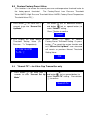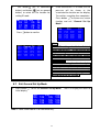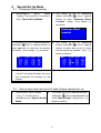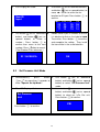
1
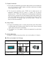
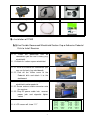
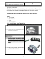
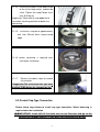
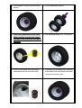
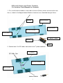
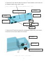
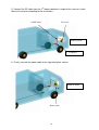
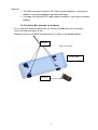
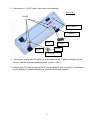
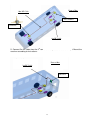
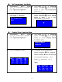
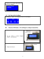
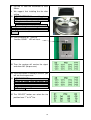
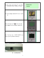
Tire Pressure Monitoring System
User Manual
Model: THC03 & THE01
Table of Content
! " # ! $ % & ' ( ) * + ) 2
3
3
3
3
4
4
! "
, 5
! - , ' 8
14
14
15
16
16
18
19
20
. / + ) % / . // + ) / , 0 / . " + ) 1 % / 2 , 2 "
" , " , 2 ", "
2 3 4 ( $ # 20
4 ## 5 - " 4 ## * " 21
22
4 ## ", " 4 + 4 ! ++ % 6 4 . 7 "8 9
9:
: %
"
, 4 2 ; & ( $
$ # < $ # < ;; & 5 - "
< ## "
, / < $ # < ", $ # < ! // 5 # < . ;; & $ # 66655 %
= ++ ) / # 666
666
% , "
, 5 , " " # 2
22
23
23
24
25
25
25
26
27
27
28
28
32
33
33
35
1Product Introduction
(1) This tire pressure monitoring system contains highly accurate sensors to detect tire
pressure and temperature; and RF modules send data via radio wave to the digital
receiver placed in driver’s cabin.
(2) The tire pressure monitoring system -THC03 starts to detect pressure and
temperature automatically when the vehicle is in motion. The tire pressure
monitoring system - THE01 starts to detect pressure and temperature automatically
when the sensor is mounted. Pressure and temperature data will be showed on the
LCD screen of digital receiver. If the pressure and temperature go wrong, the driver
will be warned with LCD backlight, beep, and flashing numbers. Therefore, the
driver can take action immediately.
2Safety Notice
(1) Tire pressure monitoring system is a vehicle safety warning system. Please follow
installation guide and instruction carefully. When the system sends out warming
signals, please check your tires immediately.
(2) This product has to be properly installed and programmed by professional
technician.
3Vehicle Application
This product is suitable for heavy-duty vehicles such as truck and bus.(4~14 wheels)
What are Included in the Package
4.1
Digital Receiver1unit
4.2 Transmitter4 ~ 14 pcs
4.3
Chassis Antenna 2~4
pcs
4.4 Power Combiner: 1~3
pcs
Cap Type
Clamp Type
THE01
THC03
4.5 Cigarette Lighter Power
Cable1 piece
3
4.6 Receiver Mount1 set
4.7 RF Cable: 3~9 pcs
4.8 Strap4~14 pcs
4.9 User Manual1 copy
Installation of TPMS
Use Flexible Gooseneck Windshield Suction Cup or Adhesive Pedestal
Disk to Install Receiver
5.1.1.1 Place the gooseneck arm on
somewhere you can see it clearly (e.g.
windshield).
5.1.1.2 Attach its suction cup on windshield.
5.1.2.1 Install the receiver on somewhere you
can see it clearly (e.g. dashboard).
5.1.2.2 Peel off the sticker cover of the
Pedestal disk and attach it to the
dashboard.
5.1.3.1 Fix receiver on the flexible gooseneck
windshield suction pedestal.
5.1.3.2 Screw antenna cable connector onto
the receiver.
5.1.3.3 Plug DC power cable into receiver
power jack and cigarette lighter
socket
???
???
???
???
5.1.4. LCD screen will show “???”
4
PSI
???
???
??? ???
???
??? ???
???
??? ???
5.1.5.
Reverse above steps to remove the receiver.
5.2 Install Transmitter
Attention: Transmitters must be installed by professional technicians. The technicians
have to follow the installation guide step by step to install transmitters correctly.
Following tools and instructions are for technicians, not for end users.
Tools
Tire Changer
Wheel Balancer
Pliers
Other Hand-tools
5.2.1 Install Clamp Type Transmitter
(Before install the tire please set up the ID of the transmitter first, refer to NO.10)
5.2.1.1 Please follow the standard procedures
to dismount tire from rim.
IMPORTANT:
5.2.1.2 Set up the ID of the transmitter and
must keep other transmitters away
from at least 1m away to avoid taking
the same signal Then install the
clamp.
5.2.1.3 Make sure arrow on the transmitter
point to rubber valve side.
5
5.2.1.4
Put the transmitter in the lowest area
of the rim or drop center, and beside
valve. Tighten the strap.(Torqre must
over 0.35 kfg-m)
Suggestion: Place lock of strap opposite to
transmitter mounting position for better tire
rebalancing.
5.2.1.5
Cut excess strap off to approximately
one 1nch (25mm); blunt sharp cutting
edge.
5.2.1.6 Wheel Balancing is required after
transmitter installation.
5.2.1.7
Reverse the above steps to remove
a transmitter.
Suggestion:Tell technician that you have
installed TPMS before he changes the tire.
5.2.2 Install Cap Type Transmitter
Please follow steps below to install cap type transmitter. Wheel balancing is
required after the installation.
>
>
IMPORTANT: Install NO.5.3 first then turn on the Receiver and go to the
General Set Up Mode/Search TX ,then place the transmitter one by one
6
1. For example: Install in rear axial twin
2. Disassemble twin wheels
wheels
4. Set tightened torque at 9~10 Kgf.cm.
3. Place the transmitter on the valve.
Make sure the one gets the signal
and wait 2 mins then you can go to
the next.
5. Fasten inner wheel with transmitter
mounted to the transmission shaft.
6. Complete the installation by fastening
outer wheel with transmitter mounted
to the transmission shaft.
7
5.3 Install Antenna and Power Combiner
5.3.1 Install on Truck (Example for 10 wheels)
1. First, install antenna modules at two sides of chassis(Frame), which are close to the rear
tires as shown in the diagram below. Bottom of antenna case should be facing to fixture.
Wheel of Truck
Antenna
Front of Truck
Top view of Truck
Rear of Truck
A Part of
Antenna
Band
2. Connect two 1.5 m RF cables from antenna to 1st power combiner.
Combiner
1st Combiner
Top view of Truck
Rear of Truck
Antenna Module
8
Frame
3. Connect one end of 10m RF cable to the output of 1st power combiner, and the other end
to 2nd power combiner input in driver’s cabin.
2nd Combiner
Top view of Truck
Front of Truck
1st Combiner
Rear of Truck
Input
Iutput
Output
Combiner
4. Connect a 6m RF cable line to input of the second power combiner, pull it to the chassis
and connect it to the antenna module for front wheels.
2nd Combiner
Front of Truck
The antenna for front wheels
Cable
9
5. Connect 2m RF cable from the 2nd power combiner’s output to the receiver’s input.
Mount the receiver according to the instructions.
2m RF cable
Receiver
Front of Truck
2nd Combiner
6. Finally, connect the power cable to the cigarette lighter socket.
Front of Truck
Power cable
10
Attention:
1. The SMA connections between RF Cables, power combiners, and antenna
modules should be wrapped using water-proof tape.
2. Use cable ties to bind the RF cables, power combiners, and antenna modules
properly.
5.3.2 Install on Bus (example for 6 wheels)
1. First, install four antenna modules on any fixtures available that are fastened on
chassis(Frame) and close to tires.
Bottom of antenna should be facing to fixture as shown in the diagram below.
Antenna
Top view of Bus
Front of Bus
Antenna
11
2. Connect four 1.5 m RF cables from antenna to combiner.
Front of Bus
1.5m RF
3rd Combiner
2nd Combiner
Intput
Antenna
Output
Intput
1st Combiner
3. Connect one end of 10m RF cable line to the output of the 1st power combiner for rear
wheels, and the 3rd power combiner input in driver’s cabin.
4. Connect a 6m RF cable to intput of the 3rd power combiner, pull it to chassis and connect
it to the output of 2nd power combiner for front wheel antenna modules.
12
Front of Bus
10m RF Cable
3rd Combiner
Combiner
6m RF Cable
5. Connect 2m RF cable from the 3rd combiner’s output to the receiver’s input. Mount the
receiver according to instructions.
Front of Bus
2m RF Cable
Receiver
13
6. Finally, connect the power cable to the cigarette lighter socket.
Power Line
Attention:
1. The SMA connections between RF Cables, power combiners, and antenna modules
should be wrapped using water-proof tape.
2.Use band to bind the RF cables, power combiners, and antenna modules properly.
6. Digital Receiver Function Description
6.1
Digital Receiver Diagram, Display Control and Indicators
LED Alarm Indicator
Setting Mode
LCD Backlight
LCD
Pressure
Temperature
14
6.2 The Receiver Button Function Description
1.Temperature
Button
Display temperature of tires after press button . If no data
received, the corresponding tire pressure will be displayed
as ???.
2.
35
36
36
???
36
36
36
35
35
35
35
35
35
???
(Downward In “General Set Up Mode”acts as downward button to
Button)
select function and number.
3.Backward Button
In “Special Set Up Mode”acts as backward button to
select tire for programming.
1.Pressure Button
Display pressure of tires after press button
.If no data
received, the corresponding tire pressure will be displayed
as ???.
125
125
125
???
2.(Upward Button)
PSI
125
125
125 125
125
125 125
125
125 ???
In “General Set Up Mode” acts as upward button to
select function and number.
In “Special Set Up Mode”acts as forward button to select
3.Forward Button
tire for programming.
1.LCD
Display
Backlight Button
Set
to switch the backlight of LCD Display.
125
125
125
125
2.Confirmation
Button
1.Activate
Button
Press button
PSI
125
125
125 125
125
125 125
125
125 125
In set up modebutton
Up
Press button
more than 2 seconds to enter into
“General Setup Mode”.
15
acts as confirmation button.
2.Exit Set Up Mode
Press button
again to exit “Setup Mode”.
NoteValues shown above are for reference only.
7. Alarms and Warnings
7.1
1.
Pressure Threshold Alarm and Warning
Tire pressure lower/higher than Manual
Pressure Threshold Setting
Low/High Pressure Warning is initiated
*Remark:
The manual
pressure thresholds suggested being
when the pressure drops below /rises above the lower than 108 PSI and higher than
programmed Pressure Threshold Setting Limit. 144PSI. The pressure threshold
value is adjustable by user.
Warning Actions Include
Example:
(1) LED Alarming Indicator blinks once.
(2) Two short audio alarms.
When the tire pressure is lower than
threshold, the LCD display will show
something as below and initiate the
pressure warning.
Suggested Action to Warning
When the warning occurs, reduce
speed and proceed to a safe
location to check tires.
2.
!85
125
125
125
PSI
125
125
125
125
125
125
125
125
125
125
Tire pressure drops below the
Factory-Preset Low Pressure Threshold
Setting
Low Pressure Alarm is initiated when the
Remark:
The low tire pressure warning value
is set as 75% of the cold tire
pressure.
pressure drops below the Factory-Preset
Threshold Setting Limit.
(1) The cold tire pressure for valve
cap transmitter is the initial
pressure detected while the
Alarm Actions Include
(1) LED Alarm Indicator blinks once.
transmitter screwed on the tire.
(2) Three short audio alarms.
(3) LCD Display Backlight remains on The
pressure value of the anomalous tire will be kept
flashing and shown on the associated tire
location.
To Cancel Alarm actions
Proceed “Reset” function as described on
“General Set Up Mode” Section 8.4. Or
16
(2)The cold tire pressure for clamp
type transmitter is the tire pressure
detected while the transmitter is
waking up by its centrifugal switch.
(if the tire pressure is below
120PSI, the cold tire will be
detected as 120PSI, e.g. the low
the low pressure warning will remain on the
display even re-power the receiver.
Suggested Action to Alarm
When the alarm occursreduce speed and
proceed to a safe location to check tires.
NoteThe Pressure Deflation Alarm will disappear
when the tires are properly re-inflated to
correct levels.
!85
125
125
125
PSI
125
125
125 125
125
125 125
125
125 125
tire pressure warning value will be
90PSI.
90
125
125
125
PSI 125
125
125 125
125
125 125
125
125 125
Example:
When the tire pressure is 85PSI,
the LCD display will remain as
left and the warning will activate.
3.
Leak Warning
When the tire pressure decline rate is over
10PSI/minute(fast leaks) or 12PSI/10
min.(slow leaks), the transmitter will
initiate the warning. The tire pressure and
the !!!! warning signal will flash with
interchanging.
NoteThe leak warning might be wrongly initiated
if the tire pressure is dramatically
changed, esp. under the heavy rain or
the significant temperature falls.
NoteValue shown above is for reference only.
17
!!!!
125
125
125
PSI
125
125
125 125
125
125 125
125
125 125
7.2 Temperature Threshold Alarm and Warning
1.
Note:
The default manual threshold Setting
Tire Temperature higher than Manual
Temperature Threshold Setting
High Temperature Warning is initiated when Limit is 75°C.
detected tire temperature is above the
programmed Temperature Threshold Setting
Limit.
Warning Actions Include:
Example:
When the tire temperature is
(1) LED Alarming Indicator blinks once.
(2) Two short audio alarms.
(3) The pressure value of the associated tire
flashes once
Suggested Action to warming
When the warning occursreduce
speed and proceed to a safe location to
check tires.
2.
80°C,the LCD display will remain
as below and the warning will
activate.
80
36
36
36
36
36
36
35
35
35
35
35
35
35
Tire Temperature higher then Factory-Preset Example:
Temperature Threshold Setting
When the tire pressure is 86°C,the
High Temperature Alarm is initiated when tire
LCD display will remain as below
temperature rises above the Factory-Preset
and the warning will activate.
Temperature Threshold Setting Limit.
Alarm Actions Include:
(1) LED Alarming Indicator flashes once.
(2) Three short audio alarms.
(3) LCD Display Backlight remains onThe
temperature value of the
anomalous tire will be kept flashing
and shown on the associated tire
location.
To Cancel Alarm actions
Proceed “Reset” function as depicted on
“General Set Up Mode” Section 8.4. Or
the low temperature warning will remain on
the display even re-power the receiver.
Suggested Action to Alarm
When the alarm occurs,reduce speed and
proceed to a safe location to check tires.
18
!86
36
36
36
36
36
36
35
35
35
35
35
35
35
Note:
The Factory-Preset
Temperature Threshold Setting Limit
is set at 85°C in the transmitter
firmware.
7.3 Other Warnings
1.
Communication failure warning
When the receiver has not received a
transmitter signal over 30 min., the ????
symbols will be shown on LCD display at the
corresponding position. If the above
symbols continuously remains on the display,
the system might be poorly communicated or
malfunctioned. Please return to the original
manufacturer for further inspection.
????
PSI
125 125
125
125 125
125
125 125
125
125
125
125
125
E01
PSI
125 125
125
125 125
125
125 125
125
125
125
125
125
E02
PSI
125 125
125
125 125
125
125 125
125
125
125
125
125
E03
PSI
125 125
125
125 125
125
125 125
125
125
125
125
125
NoteIf the receiver restarts, the counter will
recount.
2.
ID correctness failure warning
Once turning on the receiver, the transmitter
ID code will be checked automatically. If the ID
identification failed, the LCD display will display
E01 signal as warning.
Note:
If the ID identification failure warning occurs,
please re-setting the transmitter ID code.
3.
Low Battery Warning
The low battery warning will be initiated while
the transmitter is going to run out of battery.
The tire pressure and the E02 warning digit
will also flash alternately on the LCD display.
Note:
If the transmitter low battery warning occurs,
please replace it with new transmitter.
4. Sensor Malfunction Warning
While the pressure and temperature sensing
functions failed during sensor detection, the
tire pressure and the E03 warning digit will flash
alternately on the LCD display.
Note: Please replace it with new transmitter.
NoteValue shown above is for reference only
19
8.
General Set Up Mode
8.1 Manual Low Pressure Threshold Setting
1.
3.
Press button
for more than 2 2.
seconds to go into “General Set Up
Use button
(act as downward
button) and button
(act as upward
Mode”.
button) to select “Low
Warning “ setting.
LCD Display will show
4.
Low Pressure
Warning
Press
5.
Use button
(act as downward
button) or
(act as upward button)
to select the setting for all or single tire.
Press
button to confirm.
ALL
button to confirm
If select SINGLE tire, use button
6.
Pressure
SINGLE
OR
Use button
(act as downward
(act as downward button) or button
(act as upward button) to select the tire
location for setting. Press
button
button) or
(act as upward button)
to select the low tire threshold setting
value. Press
button to confirm
to confirm.
the pressure value. Or press button
to cancel the above setting and exit
“General Set Up Mode”.
01 Pick Tire
03 04
05
07 08
09
11 12
13
02
06
10
14
108 PSI
20
8.2 Manual High Pressure Threshold Setting
1.
Press button
for more than 2 2.
seconds to enter “General Set
Up Mode”.
Use button
(act as downward
button) and button
(act as
upward button) to select “High
Pressure Warning “ setting.
3.
LCD Display will show
Press button to confirm
4.
High Pressure
Warning
Use button
(act as downward
button) or
(act as upward
button) to select the setting for all
or single tire.
to confirm.
ALL
5.
If select SINGLE tire, use button
(act as backward button) or
(act as forward button)
button
to select the tire location for
setting. Press
button to
confirm.
01 Pick Tire
03 04
05
07 08
09
11 12
13
02
06
10
14
6.
Press button
OR
Use button
SINGLE
(act as downward
button) or
(act as upward
button) to select the high
pressure threshold setting value.
Press
button to confirm the
pressure value. Or press button
to cancel the above setting
and exit “General Set Up
Mode”.
144 PSI
21
8.3 Manual Temperature Threshold Setting
1.
Press button
for more than 2 2.
seconds to enter “General Set Up
Mode”.
Use button
(act as downward
button) and button
(act as upward
button) to select “High Temperature
Warning” setting.
3.
LCD Display will show
Press button to confirm
4.
High Temperature
Warning
Use button
(act as downward
button) and button
(act as upward
button) to select a number as High
Temperature Threshold.
75 5.
Press button
to confirm setup
again to
value. Or press button
exit “General Set Up Mode”.
8.4
Reset(Clear present pressure and temperature values. This procedure will also
cancel alarm status temporarily)
1. Press button
for more than 2 2. Use button
(act as downward button)
second to enter “General Set Up
and button
(act as upward button)
Mode”.
to select “Reset” setting.
RESET
3. Press button
to confirm.
4. All previous pressure and temperature
figures will be clear and show “ ???”.
This main function is used to remove
the display of low pressure warning.
OK
22
8.5 Restore Factory-Preset Value
(This function is to restore the manual pressure and temperature threshold value to
the factory-preset threshold.
The Factory-Preset Low Pressure Threshold
Value=108PSI, High Pressure Threshold Value=144PSI; Factory-Preset Temperature
Threshold Value=75)
for more than 2 2.
1. Press button
seconds to go into “General Set
Up Mode”.
Use button
and button
(act as downward button)
(act as upward button) to
select “Default” setting.
Press button to confirm
Default
3. LCD Display will show default 4. Press button
again to confirm
Threshold Setting Value (P=
Factory-Preset Threshold Setting. Or press
PressureT = Temperature).
button
to cancel the restore function and
P=108/144 PSI
T=75 exit “General Set Up Mode”. and Threshold
will remain as previous Manual Threshold
Setting Value.
OK
8.6
1.
“Search TX”—for Valve Cap Transmitter only
(act as downward button)
Press button
for more than 2 2. Use button
(act as upward button) to
seconds to enter “General Set Up and button
select “Search TX” setting. Press button
Mode”
to confirm.
Search Tx
23
3.
Use button
(act as downward 4.
button) and button
(act as upward
Once received the TX ID code, the tire
pressure will be shown at the
button) to select the tire location for
setting ID code.
associated tire location on the display.
Transmitter searching then completes.
Press button
to cancel the search
function and exit “General Set Up
01 Pick Tire
02
03 04
05 06
07 08
09 10
11 12
13 14
Press
Mode”.
125
PSI
??? ??? ???
??? ??? ???
??? ??? ???
button to confirm
???
???
???
???
Note:
???
???
???
???
Search TX
??? ???
??? ???
??? ???
???
???
???
???
1. All ID setting should be finished
within two minutes. Or the receiver will
stop searching automatically. And when
you install the next transmitter, please
wait 2mins or displace the former
transmitter.
2. The TX searching function is only for
valve cap transmitter. For the initial
installation on tires, each valve cap
transmitter should do the pairing setting
according to the 8.6 section.
8.7 Exit General Set Up Mode
1.
Press button
to exit the General Set Up Mode.
initial display.
125
125
125
125
PSI
125
125
125 125
125
125 125
125
125 125
NoteValue shown above is for reference only.
24
The LCD Display will return to
9
Special Set Up Mode
9.1
1.
Exchange Wheel Location
Simultaneously
press
button 2.
and
for more than 2 seconds to
enter “Special Set Up Mode”.
Use button
(act as downward
button) and button
(act as upward
button) to select ”Exchange Wheel
Location” setting.
to confirm.
Press button
Exchange Wheel
Location
3. Use button
(act as downward button) 4.
and button
(act as upward button) to
move cursor to select the tire location
Use button
(act as downward
button) and button
(act as upward
button) to move cursor to select
for rotationPress button
the tire location for rotationPress
button to confirm.
01 Pick Tire
03 04
05
07 08
09
11 12
13
5.
02
06
10
14
01 Pick Tyre
03 04
05
07 08 09
11 12
13
02
06
10
14
Repeat the above setting procedures
until all Transmitter ID codes are set to
the associated tire location on the
display.
9.2
1.
to confirm.
Manual input new transmitter ID code (Please contact with us)
Simultaneously press button
and
for more than 2
seconds to enter “Special Set Up
Mode”.
2.
Use button
and button
(act as downward button)
(act as upward button) to
select “New ID Input” settingPress
button to confirm.
25
3.
5.
LCD Display will show
4.
Use button
and button
New ID
Input
move cursor to select the tire
location for ID inputPress button
confirm.
Use button
(act as downward 6.
button) and button
(act as
upward button) to select a
number Press button
to
Double check input ID number to ensure
it is identical to that on the Label of new
TransmitterPress button
to confirm
and complete the setting. Then install
confirm then move to the next
numberPress button to cancel.
(The ID below is for reference )
the transmitter in the associated tire
9.3
OK
Set Pressure Unit Mode
Simultaneously
press
button 2.
and
for more than 2 seconds to
enter “Special Set Up Mode”.
3.
to
01 Pick Tire
02
03 04
05 06
07 08
09 10
11 12
13 14
ID5A1B001A
1.
(act as downward button)
(act as upward button) to
The LCD Display will show
(act as downward
button) and button
(act as upward
button) to select ”Set Pressure Unit”
mode.
4.
Use button
(act as downward
button) and button
(act as upward
button) to select psi, kPa, Bar unit.
Press button
to confirm.
Set Pressure
Unit
Press button
Use button
PSI
to confirm.
26
9.4
1.
Set Temperature Unit Mode
Simultaneously
press
button 2.
and
for more than 2 seconds to
enter “Special Set Up Mode”.
3.
The LCD Display will show
Press button
Use button
(act as downward
button) and button
(act as upward
button) to select ”Set Temperature
Unit” setting.
4.
to confirm.
Use button
(act as downward
button) and button
(act as upward
button) to select or unit.
Press button
to confirm.
Set Temperature
Unit
9.5
1.
Display Wheel Location Mode
Simultaneously
press
button 2.
and
for more than 2 seconds to
Use button
(act as downward
button) and button
(act as upward
enter “Special Set Up Mode”.
button) to select” Display Wheel
Location” setting.
Display Wheel
Location
Press button
3.
The LCD Display will show
4.
to confirm.
Use button
(act as downward
button) and button
(act as upward
button) to move
cursor to select the
wheel location for display.
01* Location 02*
03* 04* 05* 06*
07* 08* 09* 10*
11* 12* 13* 14*
button
Press
to cancel or set signal.
01* Location
03 04 05
07* 08* 09*
11* 12* 13*
27
02*
06
10*
14*
5. Press
to confirm and return to
“Special Set Up Mode”.
Display Wheel
Location
9.6
Exit Special Set Up Mode
Press button
125
125
125
againLCD Display will return as initial display.
PSI
125
125
125
125
125
125
125
NoteValue shown is for reference only.
POWER CABLE
1.
Put the 12DCV or 24DCV POWER
CABLE to the Receiver.
Antenna
2.
Tighten the Antenna.
28
3.
Check if the LCD of the Receiver shows
“???“.
4 Simultaneously press button
and for
more than 2 seconds to enter “Receive ID
Mode”.
5 Check if the LCD of the Receiver shows.
“Receive ID“.
6
Turn on the LF.
7
Check if the LCD of the LF shows “01“.
29
8
Put the LF near the transmitter at least
30mm.
We suggest that installing the tire after
setting.
10 IMPORTANT:When setting,please
9
keep other transmitter away from the
setting transmitter at least 1m
NOTE:If you are not sure it receives
the signal or not please do it again or refer
to NO.< 7Manual input new transmitter ID
code9 11 Push the button of “ENTER”
And the “SEND” LED will flash.
12 Then the receiver will receive the signal
and show “00” (No pressure)
13 If the transmitter is already in the tire ,you
will see the tire pressure.
14 IMPORTANT:If you want to check
the tire as usual ,you may push any
button of LF and the receiver will show
the pressure(The signal active distance
of LF is 1m )
15 The “SELECT” button can select the tire
position from 1st to 14th tire.
30
16 After setting, push button
the LCD of
the Receiver shows “Receive ID Cancel”
17 As the voltage is below 6.2Vthe LF shows
“LP“.
18 As recharge ,the LF
shows red ,and it
will disappear until the voltage is above 8.4V.
19 LF will turn into “SLEEP MODE” over
30secs, push any button to wake up.
NOTEThe value above is for reference.
LF CONTROLLER
31
11. Limit Warranty
Mobiletron, hereby warrants that this Mobiletron wireless tire pressure monitoring
system shall be free from material defects in workmanship and/or materials until the
expiry of twelve months from its purchase by the end user, EXCEPT WHERE any
such defect has been caused by: Improper or non-normal use, Improper installation,
contacts with any corrosive or otherwise harmful substance, any other acts or
omission not sanctioned by the User Manual.
Mobiletron warrants the wireless tire pressure monitoring system product for
twelve months from the end user purchase date under normal operation
condition, which is free from manual improper operation, improper installation or
any casualty.
Mobiletron’s sole obligation shall be to repair or replace the defective product at
no charge to the original owner.
Mobiletron warns the user or driver of the driving safety by the limited warning
signal range, and does not protect or take the responsibility of the user’s or
driver’s safety directly.
In no event will Mobiletron be liable for any direct, indirect, special, incidental or
consequential damage, including loss of profit, loss of savings, or any other
damages caused by product, or its documentation, or failure of the product to
perform, even if Mobiletron has been advised of the possibility of such damages.
11.1 Warranty Service
(1) The above warranty will be honored by the retailer from which it was
purchased, provided that the owner can provide dated proof of purchase.
(2) In the event that any defect in the unit is covered by the above warranty,
Mobiletron will replace the affected components free of charge, shipping
prepaid. The owner shall be responsible for any labor and installation costs
incurred in removing the defective parts and/or installing the replacement.
(3) The retailer shall at Mobiletron’ cost send any unit which is defective as
described in the above warranty to Mobiletron at No.39, Sec 3, Chung-Ching
Rd., Ta-Ya, Taichung Hsien, Taiwan 428.
11.2 This Limited Warranty Provided by Mobiletron Does Not Cover
(1) Product that have been subjected to abuse, accident, alteration, modification,
tampering, negligence, misuse, faulty installation, lack of reasonable care,
improper transportation, repair or service in any way that is not authorized by
Mobiletron.
(2) Any damage attributable to fire, flood, lightning strike or act of God.
32
(3) This limited warranty coverage will exclude the package material and user
manual.
(4) The damage caused from benzene, alcohol or any corrosive cleaner.
(5) Any repair should implement in Mobiletron by returning from the Mobiletron
authorized retailer.
Any repair without authorization will be excluded from
the warranty.
12. Things to Notice
Temperature Compensated Pressure Readings
(a) When a tire heats up, caused by long duration of driving or braking, the air
pressure inside the tire can also be expected to increase, e.g. tire temperature
increases 20 to 30 may lead to 3psi to 6psi pressure increment.
Never use chemical material to clean Digital Receiver.
Never take Digital Receiver apart for repair! Whenever there is problem, please
contacts dealer for repair or replacement.
To avoid the dropping during drive, ensure Digital Receiver w/ Cooling Vent Holder
is firmly adhered in car.
Check connections of DC Power Cable at both ends should no display on LCD
panel.
After the vehicle starts to move, the tire pressure and temperature couldn’t be
received on the LCD display of the Digital Receiver, please confirm if the Antenna
is loosed; then, please screw Antenna tightly to Digital Receiver.
Be sure to keep record of the Transmitter ID number for each of the corresponding
four tires on the last page of the “16. Tire Rotation Table“ (in this user manual).
Because next time if the original Transmitter is replaced by a new one, inputting
the original Transmitter ID number to the new one should be a must.
13.
Technical Specifications
Transmitter (CAP)
!
" #
$ %
&
" #
&% ' !
(
)
&% ' !
!
,
&% ' !
&
)
&% ' !
&
,
&
.
* + " * + - + 33
$ / 0 * + / 0 %((1 2 $ 3 - 4 ( " " 5 + 6$ 78( + + $ $ ; + % < * = : + > (1 ?
&
% &
9 : < " > = 5 Transmitter (CLAMP)
!
" #
$ %
&
" #
&% ' $ !
(
)
&% ' $ !7
!
,
&% ' $ !
&
)
&% ' $ !7
&
,
&
.
* + " * + - + $ / 0 * + / 0 %((1 2 $ 3 - 4 ( " " 5 + 71 ?8($ 8$ $ 1 (
+ + (?
; + % < * = : + > (
&
7 @ $ A A B + &
9 : < " > = 5 34
Digital Receiver
* + " * + &$ ' 7
)
&% ' ! ,
&% ' !
)
&% ' !
$ C $ % ,
$ / 0 @ / 0 %((1 2 $ 3 - 4 ( " " 5 + $ %87!8( 1 + + (
; + % < + @ 3 D + + < + ?
+ 9 : 14.
Manufacturer
Manufacturer: Moniletron Electronic ,Inc.
Telephone: +886-4-25683366
Address: No.39, Sec 3, Chung-Ching Rd., Ta-Ya, Fax: +886-4-25673069
Taichung Hsien, Taiwan 428
Web Site: http://www.more.com.tw
35