1
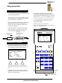
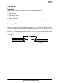
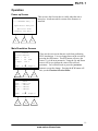
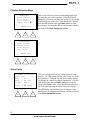
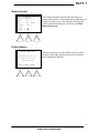
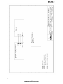
daeg D SPO2 Analyzer User and Service Manual Version 1.02_3 Updated 11/13/2002 Copyright 2002 by METRON. All rights reserved Metron Offices USA 1345 Monroe NW, Suite 255A Grand Rapids, MI 49505 Phone: (+1) 888 863-8766 Fax: (+1) 616 454-3350 E-mail: [email protected] FRANCE 30, rue Paul Claudel F-91000 Evry Phone: (+33) 1 6078 8899 Fax: (+33) 1 6078 6839 E-mail: [email protected] GERMANY Römerstrasse 22 D-63741 Aschaffenburg Phone: (+49) 6021 447 9807 Fax: (+49) 6021 447 9808 E-mail: [email protected] NORWAY Vegamot 8 N-7048 Trondheim Phone: (+47) 7395 4700 Fax: (+47) 7395 4701 E-mail: [email protected] Disclaimer METRON provides this publication as is without warranty of any kind, either express or implied, including but not limited to the implied warranties of merchantability or fitness for any particular purpose. Further, METRON reserves the right to revise this publication and to make changes from time to time to the content hereof, without obligation to METRON or its local representatives to notify any person of such revision or changes. Some jurisdictions do not allow disclaimers of expressed or implied warranties in certain transactions; therefore, this statement may not apply to you. Limited Warranty METRON warrants that the daeg SPO2 Analyzer will substantially conform to published specifications and to the documentation, provided that it is used for the purpose for which it was designed. METRON will, for a period of twelve (12) months from date of purchase, replace or repair any defective analyzer, if the fault is due to a manufacturing defect. In no event will METRON or its local representatives be liable for direct, indirect, special, incidental, or consequential damages arising out of the use of or inability to use the daeg SPO2 Analyzer, even if advised of the possibility of such damages. METRON or its local representatives are not responsible for any costs, loss of profits, loss of data, or claims by third parties due to use of, or inability to use the daeg SPO2 Analyzer. Neither METRON nor its local representatives will accept, nor be bound by any other form of guarantee concerning the daeg SPO2 Analyzer other than this guarantee. Some jurisdictions do not allow disclaimers of expressed or implied warranties in certain transactions; therefore, this statement may not apply to you. 2 www.metron-biomed.com Table of Contents Metron Offices............................................................................................................................... 2 Table of Contents .......................................................................................................................... 3 daeg D SpO2 Analyzer Specifications........................................................................................ 5 daeg Quick Start ........................................................................................................................... 7 Unit Setup ...................................................................................................................................... 9 Unpacking.................................................................................................................................. 9 Battery Installation ................................................................................................................... 9 Operation ..................................................................................................................................... 11 Power up Screen...................................................................................................................... 11 Main Simulation Screens........................................................................................................ 11 Function Selection Menu........................................................................................................ 12 Alarm Limits ........................................................................................................................... 12 Remote Control ....................................................................................................................... 13 Probe Analyzer........................................................................................................................ 13 Simulation Setup ..................................................................................................................... 14 Print Options ........................................................................................................................... 15 Troubleshooting .......................................................................................................................... 17 Calibration................................................................................................................................... 19 Schematics ................................................................................................................................... 21 3 www.metron-biomed.com This page was intentionally left blank. 4 www.metron-biomed.com daeg D SpO2 Analyzer Specifications SPO2 SIMULATION GENERAL Factory installed, downloadable and user programmable R-curves, patient conditions and templates. Probe signal and LED test x ACTIVE PROBE SPO2 SIMULATION O2 saturation range: 30 - 100 % Simulation resolution: 1% SpO2% Simulation accuracy: ± 0.5 SpO2% 65-100% SpO2% ± 1 SpO2% 30-64% SpO2% Simulation repeatability: ± 0.2 SpO2% Simulation rate: 30 - 300 bpm, res. 5 bpm (sync. to ECG for "C-lock" testing) Rate accuracy: ± 0.1% Pulse amplitude: 0 - 100% of nominal pleth amplitude. Amplitude accuracy: ≥30% amplitude ±1%. 1-29% amplitude ±5%. Pigmentation: Low, medium and high Light repeater bandwidth: DC - 1MHz Optical slew rate: 50 mcd/µs Light repeater dynamic range: 1mcd + 13 dB - 60 dB Receiver optical 3 dB bandwidth: 600 - 1050 nm. INSTALLED R-CURVES BCI International Criticare Masimo Nellcor Novametrix Philips (Agilent) Ohmeda INSTALLED PATIENT CONDITIONS Normal patient Geriatric patient Obese patient Patient with weak pulse Bradycardia Tachycardia ECG SIMULATION - GENERAL The data below is related both to factory installed and downloadable waveforms. Lead configuration: 5 lead RL, RA, LA, LL, V1-6 Low level output amplitude: 0.2-2mV, resolution 100 mV Low level output impedance: 1000 ohm to RL High level output amplitude: 0.5V/mV of low level. High level output impedance: 50 ohm System amplitude accuracy: ±2% @1mV System rate accuracy: ± 0.1% System time resolution: 10 µs (100 kHz maximum update rate) ECG OUTPUT The data below is related to factory installed waveform types. NORMAL ECG SINUS 30 - 300 BPM, resolution 1 BPM GENERAL INFORMATION POWER SUPPLY Power sources: 4 standard AA/LR6/MN-1500 cells. 230VAC/115VAC to 9vDC battery eliminator. Power consumption: 200 mA w/o display backlight. 400 mA w/full backlight. Battery lifetime: 12 h for alkaline cells without backlight. daeg SpO2 Analyzer Ordering Information Order no: 12700: daeg SpO2 Analyzer Accessories: 17021: Battery Eliminator 240V or 17027: Battery Eliminator 115V 17030: Battery Package. 4-cells 12710: User and Service Manual Options: 11150: 12711: 12712: 12713: 12714: 17024: Carrying case Cable Test Adapter Box PRO-Soft daeg PRO-Soft daeg, demo User Manual PRO-Soft daeg Universal Banana Adapter HOUSING High impact plastic case. DIMENSIONS Height: Width: Depth: 237 mm/9.2" 122 mm/4.8" 42 mm/1.6" WEIGHT With battery: 0.6 kg/1.3 lb. ARTIFACTS (ACTIVE PROBE ONLY) Motion: 0 - 4Hz Ambient sunlight: Ambient, Sun Interfering light: 50Hz, 60Hz TEMPERATURE Storage temperature: 0/32 to +50/122 ° C/F Operating temperature: + 15/59 to +35/95° C/F PROBE LED OPTICAL FREQUENCY Frequency range: 550 - 1050 nm Resolution: 1nm Accuracy: ±2% of range HUMIDITY Operating humidity: 10% - 80% (non-condensing) PROBE TEST Available with release of Probe Test Adaptor Box and firmware update. CONNECTORS 9V DC power inlet (standard 2.1 mm power jack) RS-232/C for PC or printer communication (9-pin D-sub male) 1 probe connector (Redel 8-pin). 5 low level ECG outputs RA, RL, LA, LL and V1 (AHA color coded safety connector) 1 high level ECG output (standard phono jack). DISPLAY Graphical LCD, with backlighting. 5 www.metron-biomed.com This page was intentionally left blank. 6 www.metron-biomed.com daeg Quick Start daeg Startup 1. Connect daeg’s Finger Probe to the main daeg unit, and switch the daeg unit on. The daeg must be powered by the 9VDC 400mA power supply or by 4 AA alkaline batteries loaded into the unit’s battery compartment. 2. The version number of the firmware will be briefly displayed, followed by the first display screen (below). The unit is immediately outputting the simulation as displayed. 3. To change the simulation setting for oximeter model (Make), Ambient Light, Pigmentation, or to select an automated simulation sequence, select the F3 function key to go to the second display screen. 4. To access additional test and auxiliary functions, press the F1 function key while in the first or second screen display. Additional / Auxiliary functions include: Alarm Tests, Print functions, Remote Control Operation, Probe Tests, and Simulation Setup. 3. Apply the oximeter’s sensor to the daeg finger probe. The sensor’s transmitter must be on the bottom (unlabeled) side of the daeg finger. daeg finger probe Label side to bottom. SpO2 sensor Red, IR light source introduced on unlabeled side of daeg finger. METR N SpO2 Analyzer ----------------- STATUS ---------------Preset : 7Manual SpO2 : 96 % Rate : 60 BPM P.ampl : 100 % FUNC. displ- 7Ð Daeg Operation / Simulation 1. To adjust the simulation settings, use the F2 function key to select the “active” parameter. The active parameter is marked with an asterisk (*). ------------------STATUS ---------------Preset : 7Manual SpO2 : 96 % Rate : 60 BPM P.ampl : 100 % F1 F2 F3 esc no clear yes enter template F1 F2 LED-test Red IR daeg 1 2 3 4 5 6 7 8 9 F3 Note: Menu items at the bottom of the display are activated/accessed using the F1, F2, and F3 function keys. on off 0 - . , # $ 2. Adjust the active parameter using the yellow Up and Down arrow keys on the keypad, then press enter to confirm the change. Release Battery Compartment 7 www.metron-biomed.com This page was intentionally left blank. 8 www.metron-biomed.com Unit Setup Unpacking Unpack the unit and confirm the presence of the following components: 1 - daeg main unit 1 - daeg artificial finger 4 - AA batteries 1 – battery eliminator If any of these items are missing or damaged, please contact your local Metron office. Battery Installation Refer to the diagram below when installing the batteries. You will need to depress the tabs shown in the diagram below and remove the bottom dark gray piece of the chassis. This will then expose the battery connector and battery tray. Disconnect the battery clip and remove the battery tray. When inserting the batteries into the tray, be sure to observe the polarity of the batteries. When the tray is loaded back into the unit, reconnect the clip, and then replace the chassis piece. Tabs Bottom Left Right 9 www.metron-biomed.com This page was intentionally left blank. 10 www.metron-biomed.com Operation Power up Screen ---- METRON daeg --- This screen is the first one that is visible when the unit is turned on. It indicates which version of the firmware is installed. SpO2 Meter Analyzer Revision X.XX loading sim data... F1 F2 F3 Main Simulation Screens ------ STATUS -----Preset:*Manual SpO2 : 96 % Rate : 60 BPM P.ampl: 100 % FUNC. F1 * Ð F2 displ-1 These are the two screens that are used when performing SPO2 simulations. You can change between the screens by pressing the (F3) button. The (F2) button will move the cursor, (*), to the next parameter. Using the Up and Down arrows will let you change the value of the selected parameter. You will then need to press the (yes/enter) button to accept the change. Pressing the (F1) button will take you the Function Selection Menu. F3 ------ SETUP ------Make :*Nellcor Oper. : Manual Amb.L.: Manual Pigm. : Manual FUNC. F1 * Ð F2 displ-2 F3 11 www.metron-biomed.com Function Selection Menu -----FUNCTIONS-----Alarm limits Print header Print Status Remote Contr Ð ENTER EXIT F1 F2 This screen will let you select which testing function of the daeg that you wish to perform. Using the Up and Down arrows will let you move the cursor (->) next to the function that you wish to use. Once the cursor is placed press the (F2) button or the (yes/enter) button to enter that function. Pressing the (F3) or (esc) buttons will take you back to the Main Simulation Screen. F3 -----FUNCTIONS-----Print Status Remote Contr Probe Analyz Sim. Setup ENTER EXIT F1 F2 F3 Alarm Limits AL_LIMIT t= 0.0 sec Pulse :*On SpO2 : 96 % Rate : 60 BPM P.ampl: 100 % STOPt F1 * Ð F2 PRINT F3 This test is designed to test your alarm system on your monitor. The (F2) button will move the cursor, (*), to the next parameter. Using the Up and Down arrows will let you change the value of the selected parameter. You will then need to press the (yes/enter) button to accept the change and start the timer. Press the (F1) button to stop the clock when you hear the alarm from your monitor. The (F3) button will generate a line of printout via the parallel port. Pressing the (esc) button will take you back to the Main Simulation Screen. 12 www.metron-biomed.com Remote Control ------ STATUS -----Preset:*Manual SpO2 : 96 % Rate : 60 BPM P.ampl: 100 % LOCAL CONTR. * Ð F1 F2 This is the screen that is shown when the daeg is in remote control mode. All currently active parameters are displayed on the screen. Pressing (F1) will cancel the remote control mode and take you back to the Main Simulation Screen. F3 Probe Analyzer -- PROBE ANALYZER –Choose a test to perform on the SpO2 probe. This screen will let you select which test you wish to perform on the finger probe when you have the probe tester adaptor box attached. DIODE CONTI SENSI F1 F2 F3 13 www.metron-biomed.com Simulation Setup SIM SETUP: This function lets you manually alter the R-Curves within the daeg unit. To change values, use 'Yes' –button for up, and 'No' –button for down! F1 F2 Be cautious when using this mode as you are altering the analyzer output. If you make any changes that you do not wish to keep you must turn off the daeg for 5 seconds then turn it back on. F3 Make :Nellcor RedDC:2048 IRDC :1024 Lcode: 101 Rval :0.48@SpO2:100 SAVE & SpO2- SpO2+ QUIT F1 F2 When in this mode the controls will be as follows: Up and Down arrows control the cursor position. (yes/enter) increases the indicated value. (no/clear) decreases the selected value. (F1) decreases the selected SPO2 value. (F2) increases the selected SPO2 value. (F3) Saves the changes and takes you back to the Main Simulation Screen. The saving procedure may take up to 5 minutes. Do not turn off the power during this time. F3 14 www.metron-biomed.com Print Options -----FUNCTIONS-----Alarm limits Print header Print Status Remote Contr Ð The daeg unit may be attached directly to most printers via the 25-pin parallel printer port located on the side of the unit. Information is sent to the printer in standard ASCII text format. From the (FUNCTION) menu, you may select the (Print Header) or (Print Status) items. Pressing (F2) ENTER or (yes/enter) will initiate the print command. ENTER EXIT If you select (Print Header) a header will be printed, identifying the daeg unit and version of firmware installed in the analyzer. The header provides spaces for the user to enter information concerning the identity and location of the F1 F2 F3 device being tested, as well as spaces to verify that the test has passed or failed. There are also spaces to enter the date, sign the form, and add any comments. (See page xx for example of printout.) Selecting (Print Status) will provide a line that identifies the simulation parameter (make, ambient light, pigmentation, SpO2, heart rate, and pulse amplitude. A space is also provided for recording the resulting SpO2 and rate as viewed on the oximeter. (See page 16 for example of printout.) There is also an option to print from the Alarm Limits Test. At the conclusion of a test, press (F3) to print the result of the Alarm Test. The results show the settings for the test and the time/delay until the oximeter alarm was activated. (See page 16 for example of printout.) NOTE: Many printers will hold the header and status/result lines in memory until you prompt the printer to go/advance with the print job. The printer should indicate that it is receiving or has received data when the print commands are made from daeg. 15 www.metron-biomed.com 16 www.metron-biomed.com Troubleshooting Q: A: SPO2 values do not match. Confirm that the “Make” is properly selected. Q: A: The monitor is not reading any values. Check all connections and verify if the “Red” and “IR” lights on the daeg are illuminated. 17 www.metron-biomed.com This page was intentionally left blank. 18 www.metron-biomed.com Calibration ***<<Coming Soon>>*** 19 www.metron-biomed.com This page was intentionally left blank. 20 www.metron-biomed.com Schematics The schematics on the following page are for the daeg unit and the Finger Probe. 21 www.metron-biomed.com 22 www.metron-biomed.com 23 www.metron-biomed.com 24 www.metron-biomed.com 25 www.metron-biomed.com 26 www.metron-biomed.com 27 www.metron-biomed.com 28 www.metron-biomed.com 29 www.metron-biomed.com 30 www.metron-biomed.com 31 www.metron-biomed.com 32 www.metron-biomed.com 33 www.metron-biomed.com 34 www.metron-biomed.com 35 www.metron-biomed.com 36 www.metron-biomed.com 37 www.metron-biomed.com 38 www.metron-biomed.com 39 www.metron-biomed.com 40 www.metron-biomed.com 41 www.metron-biomed.com 42 www.metron-biomed.com