1
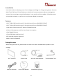
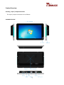
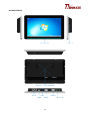
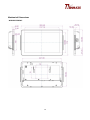
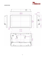
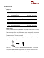
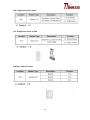
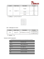
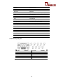
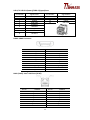
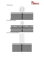
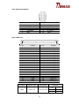
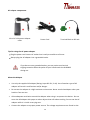
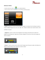
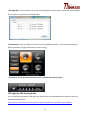
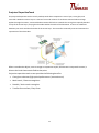
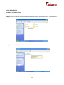
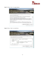
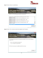
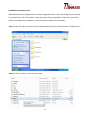
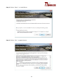
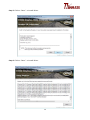
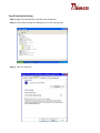
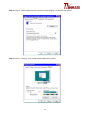
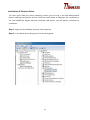
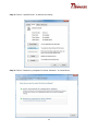
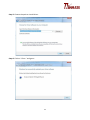
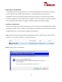
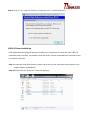
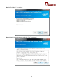
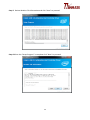
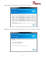
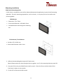
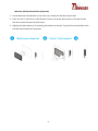
10.1” P-CAP Access Control W10IB3S-PCH2AC & W10IB3S-PCH1AC User Manual Version 1.0 1 Copyright Notice No part of this document may be reproduced, copied, translated, or transmitted in any form or by any means, electronic or mechanical, for any purpose, without the prior written permission of the original manufacturer. Trademark Acknowledgement Brand and product names are trademarks or registered trademarks of their respective owners. Disclaimer We reserves the right to make changes, without notice, to any product, including circuits and/or software described or contained in this manual in order to improve design and/or performance. We assume no responsibility or liability for the use of the described product(s), conveys no license or title under any patent, copyright, or masks work rights to these products, and makes no representations or warranties that these products are free from patent, copyright, or mask work right infringement, unless otherwise specified. Applications that are described in this manual are for illustration purposes only. We make no representation or guarantee that such application will be suitable for the specified use without further testing or modification. Warranty Our warranty guarantees that each of its products will be free from material and workmanship defects for a period of one year from the invoice date. If the customer discovers a defect, we will, at his/her option, repair or replace the defective product at no charge to the customer, provide it is returned during the warranty period of one year, with transportation charges prepaid. The returned product must be properly packaged in its original packaging to obtain warranty service. If the serial number and the product shipping data differ by over 30 days, the in-warranty service will be made according to the shipping date. In the serial numbers the third and fourth two digits give the year of manufacture, and the fifth digit means the month (e. g., with A for October, B for November and C for December). 5 For example, the serial number 1W14Axxxxxxxx means October of year 2014. Customer Service We provide a service guide for any problem by the following steps: First, visit the website of our distributor to find the update information about the product. Second, contact with your distributor, sales representative, or our customer service center for technical support if you need additional assistance. You may need the following information ready before you call: Product serial number Software (OS, version, application software, etc.) Description of complete problem The exact wording of any error messages In addition, free technical support is available from our engineers every business day. We are always ready to give advice on application requirements or specific information on the installation and operation of any of our products. Safety Information Warning! Always completely disconnect the power cord from your chassis whenever you work with the hardware. Do not make connections while the power is on. Sensitive electronic components can be damaged by sudden power surges. Only experienced electronics personnel should open the PC chassis. Caution! Always ground yourself to remove any static charge before touching the CPU card. Modern electronic devices are very sensitive to static electric charges. As a safety precaution, use a grounding wrist strap at all times. Place all electronic components in a static-dissipative surface or static-shielded bag when they are not in the chassis. 6 Safety Precautions Please read these safety instructions carefully. Please keep this user's manual for later reference. Please disconnect this equipment from any AC outlet before cleaning. Do not use liquid or spray detergents for cleaning. Use a damp cloth. For pluggable equipment, the power outlet must be installed near the equipment and must be easily accessible. Keep this equipment away from humidity. Put this equipment on a reliable surface during installation. Dropping it or letting it fall could cause damage. The openings on the enclosure are for air convection and to protect the equipment from overheating. DO NOT COVER THE OPENINGS. Make sure the voltage of the power source is correct before connecting the equipment to the power outlet. Position the power cord so that people cannot step on it. Do not place anything over the power cord. All cautions and warnings on the equipment should be noted. If the equipment is not used for a long time, disconnect it from the power source to avoid damage by transient over-voltage. Never pour any liquid into an opening. This could cause fire or electrical shock. Never open the equipment. For safety reasons, only qualified service personnel should open the equipment. If any of the following situations arises, get the equipment checked by service personnel: o The power cord or plug is damaged. o Liquid has penetrated into the equipment. o The equipment has been exposed to moisture. o The equipment does not work well or you cannot get it to work according to the user’s manual. o The equipment has been dropped and damaged. o The equipment has obvious signs of breakage. 7 Do not leave this equipment in an uncontrolled environment where the storage temperature is below -20° C (-4°F) or above 60° C (140° F). It may damage the equipment. CAUTION – Use the recommended mounting apparatus to avoid risk of injury. WARNING – Only use the connection cords that come with the product. When in doubt, please contact the manufacturer. WARNING – Ground against electrostatic damage to the device by taking the following preventive steps: o Cover workstations with approved anti-static material. Use a wrist strap connected to a work surface and properly grounded tools and equipment. o Use anti-static mats, heel straps, or air ionizer for added protection. o Handle electrostatic-sensitive components, PCB’s and assemblies by the case or the edge of the board. o Avoid contact with pins, leads, or circuitry. o Turn off power and input signals before inserting and removing connectors or test equipment. o Keep the work area free of non-conductive materials, such as ordinary plastic assembly aids and Styrofoam. o Use filed service tools, such as cutters, screwdrivers, and vacuum cleaners that are conductive. o Always lay drivers and PCB’s with the component side down on anti-static foam. Important Information Federal Communications Commission Radio Frequency Interface Statement – For USA This device complies with part 15 FCC rules. Operation is subject to the following two conditions: This device may not cause harmful interference. This device must accept any interference received including interference that may cause undesired operation. This equipment has been tested and found to comply with the limits for a class "A" digital device, pursuant to part 15 of the FCC rules. These limits are designed to provide reasonable protection against harmful interference when the equipment is operated in a commercial environment. This equipment generates, uses, and can radiate radio frequency energy and, if not installed and used in accordance with the instruction manual, may cause harmful interference to radio communications. Operation of this equipment in a residential area is likely to cause harmful interference in which 8 case the user will be required to correct the interference at him own expense. Declaration of Conformity (DoC) [English] The object of the declaration described above [A] is in conformity with the requirement of the following EU legislations [B] and harmonized standards [C]. Product also complies with the Council directions [D]. [German] Das oben beschriebene Objekt [A] entspricht den Anforderungen der nachfolgend aufgeführten EU-Vorgben [B] und den harmonisierten Normen [C]. Das Produkt entspricht außerdem den EU-Direktiven [D]. 9 Contents Copyright Notice ................................................................................................................................................... 5 Trademark Acknowledgement ............................................................................................................................. 5 Disclaimer ............................................................................................................................................................. 5 Warranty............................................................................................................................................................... 5 Customer Service.................................................................................................................................................. 6 Safety Information................................................................................................................................................ 6 Safety Precautions ................................................................................................................................................ 7 Important Information ......................................................................................................................................... 8 Declaration of Conformity (DoC) .......................................................................................................................... 9 Introduction ........................................................................................................................................................ 13 Features .............................................................................................................................................................. 13 PackageContents ................................................................................................................................................ 13 ProductOverview ................................................................................................................................................ 14 Drawing Input / Output Instruction ............................................................................................................... 14 Mechanical Dimensions...................................................................................................................................... 16 GETTING STARTED .............................................................................................................................................. 18 Jumpers .......................................................................................................................................................... 18 Jumper list .................................................................................................................................................. 18 Jumper settings .......................................................................................................................................... 18 Connectors and Pin assignments.................................................................................................................... 21 COM1: RS232/422/485............................................................................................................................... 22 USB 1/2: USB 3.0 (Lower)/USB2.0 (Upper)Ports ........................................................................................ 23 HDMI: HDMI Connector.............................................................................................................................. 23 LAN1 (LAN2): Intel® LAN Ports (RJ-45) ........................................................................................................ 23 1394b (optional) ......................................................................................................................................... 24 SPK: 2W External Speaker .......................................................................................................................... 24 Audio: Line_in / Line_out / Mic_in ............................................................................................................. 24 VGA: VGA Internal Wafer ........................................................................................................................... 25 LVDS: LVDS Port .......................................................................................................................................... 25 SATA II: SATA 2.0 Port................................................................................................................................. 26 SATA Power ................................................................................................................................................ 26 CPU Fan....................................................................................................................................................... 26 GPIO: General Purpose I/O ......................................................................................................................... 27 10 USB 3/4 (USB 5/6): USB 2.0 Wafer ............................................................................................................. 27 COM2 (COM3 / COM4): RS232 ................................................................................................................... 28 Using the AC power adapter. ............................................................................................................................. 28 Perform the following to connect the Panel PC to AC to DC Adapter: ........................................................... 28 AC adapter components ................................................................................................................................. 29 Tips for using the AC power adapter .............................................................................................................. 29 About the Adapter .......................................................................................................................................... 29 How to turn on the device.................................................................................................................................. 30 Connecting to Power Supply .......................................................................................................................... 30 Perform the following to connect the Panel PC to AC to DC Adapter: ........................................................... 30 Turning off the device ........................................................................................................................................ 30 Software Utilities ................................................................................................................................................ 31 “Utilities”- ....................................................................................................................................................... 31 “Brightness”.................................................................................................................................................... 31 “Volume” ........................................................................................................................................................ 31 “LED Light Bar” ............................................................................................................................................... 32 “Performance”................................................................................................................................................ 32 “Touch lock” Using touch lock button to lock / unlock the touch function. .................................................. 32 LED Light Bar SDK Porting Guide ........................................................................................................................ 32 Projected CapacitiveTouch .................................................................................................................................. 33 Driver Installation ............................................................................................................................................... 34 Installation of Chipset Driver .......................................................................................................................... 34 Installation of Graphic Driver ......................................................................................................................... 37 Panel Resolution Setting..................................................................................................................................... 41 Installation of Ethernet Driver ............................................................................................................................ 43 Audio Driver Introduction .................................................................................................................................. 46 Installation of Audio Driver............................................................................................................................. 46 USB 3.0 Driver Installation.................................................................................................................................. 47 Mounting Installation ......................................................................................................................................... 51 PCAP Series Mounting Guide.......................................................................................................................... 51 VESA Mount ................................................................................................................................................ 51 Flush Mount / Panel Mount: ...................................................................................................................... 51 Winmate VESA Bracket Mount (Optional): ................................................................................................ 52 SPECIFICATIONS .................................................................................................................................................. 53 11 Hardware Specifications ................................................................................................................................. 53 W10IB3S-PCH2AC ....................................................................................................................................... 53 W10IB3S-PCH1AC ....................................................................................................................................... 54 Restoring Operating System ............................................................................................................................... 55 Using Recovery Wizard to Restore Panel PC......................................................................................................... 55 12 Introduction Interactive and smart display system of an intelligence building is in a fast growing phase. Winmate Multi Touch Flat Panel PC and Display are suitable for home automation and room management systems. By connecting to centralized database, it can provide real time update for booking status and available schedule, or perform as a synchronous display in meetings. Features •10.1” 1280 x 800 Resolution with P-Cap Multi-touch Screen (W10IB3S-PCH2AC) •10.1” 1204 x 600 Resolution with P-Cap Multi-touch Screen (W10IB3S-PCH1AC) • Low-Power System with Intel® Celeron® N2930 Processor •Fanless Cooling System and Ultra-low Power Consumption • Dual Gigabit Ethernet • Front IP65 Water and Dust Proof •LED Light Bar Indicator (Optional) •Built-in HF RFID (Optional) PackageContents Before using this Panel PC, please make sure that all the items listed below are present in your package 10.1” Panel PC Power Cord AC to DC Power Adapter External USB cable Driver CD & Manual VESA Mounting Screw 13 Terminal Block 3 pin ProductOverview Drawing Input / Output Instruction The input / output instruction are as follows: W10IB3S-PCH2AC 14 W10IB3S-PCH1AC 15 Mechanical Dimensions W10IB3S-PCH2AC 16 W10IB3S-PCH1 17 GETTING STARTED Jumpers Jumper list The following table lists the function of each of the board's jumpers. Label Function Note JP1 Inverter Voltage Select 3x1 header , pitch 2.0mm JP2 Inverter Enable Select 3x1 header , pitch 2.0mm JP4 DC Mode Control 3x1 header , pitch 2.0mm JP5 From SoC Brightness PWM Voltage Select 3x1 header , pitch 2.0mm JP6 Brightness Control Select 3x1 header , pitch 2.0mm JP7 Brightness Control to VRD 3x1 header , pitch 2.0mm JP8 COM Port Select 2x3 header , pitch 2.0mm JP9 COM Port Select 3x4 header , pitch 2.0mm JP10 VRD Brightness Function 3x1 header , pitch 2.0mm Jumper settings A metal-bridge jumper used to close an electric circuit, and it usually consists of two metal pins and one small clip protected by a plastic cover that slides over the pins to connect them. Users can connect the pins with the clip to close a jumper, and remove the clip to open a jumper. Generally, a jumper will have three pins which labeled 1, 2, and 3. In this case, you would connect either pins 1 and 2, or 2 and 3. The jumper setting diagram is as below. If a jumper shorts pin 1 and pin 2, the setting diagram is shown as the right one. 1 2 3 A pair of needle-nose pliers may be helpful when working with jumpers. If you have any doubts about the best hardware configuration for your application, contact your local distributor or sales representative before you make any changes. 18 JP1 : Inverter Voltage Select JP2 : Inverter Enable Select JP4 : DC Mode Control JP5 : From SoC Brightness PWM Voltage Select 19 JP6 : Brightness Control Select JP7 : Brightness Control to VRD JP8/JP9 : COM Port Select 20 JP10 : VRD Brightness Function Connectors and Pin assignments The table below lists the function of each of the board’s connectors. Label Function DC Jack 12V Power Input COM1 RS232/422/485 USB 1/2 USB 3.0/USB2.0 Ports HDMI 1 HDMI Connector LAN1 / 2 Intel® LAN Ports 1394b 1394b (optional) SPK 2W External Speaker Audio Line_in / Line_out / Mic_in VGA VGA Internal Wafer LVDS LVDS Port 21 SATA II SATA 2.0 Port SATA Power SATA Power CPU Fan CPU Fan Front Panel System Function (Power / Reset) 3.3V 3.3V Output 5V 5V Output 12V 12V Output GPIO General Purpose I/O 12V DC Input 12V DC Power Input Wafer USB 3/4 USB 2.0 Wafer USB 5/6 USB 2.0 Wafer COM2 RS232 COM3 RS232 COM4 RS232 Mini PCIe Full / Half-Size Mini PCIe Mini Card Slot For mSATA SSD Card DDR3L SO-DIMM DDR3L SO-DIMM Socket COM1: RS232/422/485 Pin No. 1 3 5 7 9 SYMBOL DCD TxD GND RTX RI Pin No. 2 4 6 8 22 SYMBOL RxD DTR DSR CTS USB 1/2: USB 3.0 (Lower)/USB2.0 (Upper)Ports Pin Number 1 2 3 4 5 6 7 8 Signal Name +5VUSB3.0 U2DN0 U2DP0 USB_GND U3RXDN1 U3RXDP1 USB_GND U3TXDN1 9 U3TXDP1 Pin Number 10 11 12 13 Signal Name +5VUSB2.0 U2DN1 U2DP1 USB_GND HDMI: HDMI Connector Pin No. 1 3 5 7 9 11 13 15 17 19 SYMBOL HDMIB_TMDS0+ HDMIB_TMDS0GND HDMIB_TMDS2+ HDMIB_TMDS2GND GND HDMI_DDC_CLK GND HDMI_HPD1 Pin No. 2 4 6 8 10 12 14 16 18 SYMBOL GND HDMIB_TMDS1+ HDMIB_TMDS1GND HDMIB_CLK+ HDMIB_CLKNC HDMI_DDC_DATA +V5S LAN1 (LAN2): Intel® LAN Ports (RJ-45) Pin No. 1 3 5 7 9 11 13 15 SYMBOL MDI0_IN+ MDI1_IN+ VLAN_12 MDI2_IN+ MDI3_IN+ LAN_VDD LAN_SPD100LED# UGND 23 Pin No. SYMBOL 2 4 6 8 10 12 14 16 MDI0_INMDI1_INLAN1_DGND MDI2_INMDI3_INLAN_TRAFFICLED# LAN_SPD1000LED# UGND 1394b (optional) Pin No. 1 3 5 7 9 SYMBOL Pin No. 1394b_TPB0+ 1394b_TPB0GND +V12S N/C 2 4 6 8 10 SYMBOL 1394b_TPA0+ 1394b_TPA0GND N/C N/C SPK: 2W External Speaker Pin No. 1 SYMBOL Pin No. LOUT+ Pin No. 1 2 SYMBOL ROUT+ SYMBOL LOUT- Pin No. 2 SYMBOL ROUT- Pin No. 2 4 6 8 10 12 SYMBOL AZ_FOUT_L AUGND LINE1_L MIC1_L Font_SENSE Line_SENSE Audio: Line_in / Line_out / Mic_in Pin No. 1 3 5 7 9 11 SYMBOL AZ_FOUT_R +5VA LINE1_R MIC1_R AUGND Mic_SENSE 24 VGA: VGA Internal Wafer Pin No. 1 3 5 7 9 SYMBOL DAC_SDAT0 DAC_SCL0 3VHSYNC0 3VVSYNC0 GND Pin No. 2 4 6 8 10 SYMBOL VGA_5V R_FILTER G_FILTER B_FILTER GND SYMBOL Pin No. SYMBOL LVDS: LVDS Port Pin No. 1 3 5 7 9 11 13 15 17 19 21 23 25 27 29 31 33 35 37 39 Location CON5 LCDVDD LCDVDD LCDVDD GND GND GND GND GND GND GND GND GND GND GND GND GND GND GND GND GND Header Type Header 2*3 2 4 6 8 10 12 14 16 18 20 22 24 26 28 30 32 34 36 38 40 Description LVDS VOLTAGE 25 TXOUT_L0TXOUT_L0+ TXOUT_L1TXOUT_L1+ TXOUT_L2TXOUT_L2+ TXCLK_LTXCLK_L+ TXOUT_L3TXOUT_L3+ TXOUT_U0TXOUT_U0+ TXOUT_U1TXOUT_U1+ TXOUT_U2TXOUT_U2+ TXCLK_UTXCLK_U+ TXOUT_U3TXOUT_U3+ Function 3.3V 1-2 5V 12V 3-4 5-6 SATA II: SATA 2.0 Port Pin No. SYMBOL Pin No. SYMBOL 1 GND 2 SATA_TXP 3 SATA_TXN 4 GND 5 SATA_RXN 6 SATA_RXP 7 GND SYMBOL Pin No. 2 4 6 8 SYMBOL +12V GND GND VCC SYMBOL GND SENSE Pin No. 2 SYMBOL +12V SATA Power Pin No. 1 3 5 7 +12V GND GND VCC CPU Fan Pin No. 1 3 26 GPIO: General Purpose I/O Pin No. SYMBOL Pin No. SYMBOL 1 GND 2 +V5A 3 DOUT3 4 DOUT1 5 DOUT2 6 DOUT0 7 DINT3 8 DINT2 9 DINT1 10 DINT0 11 GPIO53_IN0 12 GPIO56_OUT0 13 GPIO54_IN1 14 GPIO57_OUT1 USB 3/4 (USB 5/6): USB 2.0 Wafer Pin No. 1 3 5 7 SYMBOL VCC DATA0DATA0+ GND Pin No. 2 4 6 8 27 SYMBOL VCC DATA1DATA1+ GND COM2 (COM3 / COM4): RS232 Pin Signal Name Pin Signal Name 1 FK_NDCD[2:4] 2 FK_NDSR[2:4] 3 FK_NSIN[2:4] 4 FK_NRTS[2:4] 5 FK_NSOUT[2:4] 6 FK_NCTS[2:4] 7 FK_NDTR[2:4] 8 FK_NRI[2:4] 9 GND 10 GND Using the AC power adapter. Perform the following to connect the Panel PC to AC to DC Adapter: 1. Plug the power cord into the power adapter. 2. Connect the terminal block cable with power adapter 3. Plug the Terminal block cable to the W10IB3S 4. Plug the power cord into a working AC wall outlet and the device will boot automatically Power cords vary in appearance by region and country. Note 28 AC adapter components AC to DC 12V power Adapter cable Power Cord Terminal Block to DC Jack Tips for using the AC power adapter ˙Plug the power cord into an AC outlet that is easily accessible at all times. ˙Always plug the AC adapter into a grounded outlet. Caution If you do not use a grounded outlet, you may notice an electrical tingling sensation when the palms of your hands touch the W10IB3S during use. About the Adapter • Use only the supplied AC adapter (Rating: Input DC 15V, 2.4A). Use of another type of AC adapter will result in malfunction and/or danger. • Do not use the adapter in a high moisture environment. Never touch the adapter when your hands or feet are wet. • Allow adequate ventilation around the adapter when using it to operate the device . Do not cover the AC adapter with paper or other objects that will reduce cooling. Do not use the AC adapter while it is inside a carrying case. • Connect the adapter to a proper power source. The voltage requirements are found on the 29 product case and/or packaging. • Do not use the adapter if the cord becomes damaged. • Do not attempt to service the unit. There are no serviceable parts inside. Replace the unit if it is damaged or exposed to excess moisture. How to turn on the device Connecting to Power Supply The Panel PC operates on external DC power. It is strongly recommended to use the AC to DC adapter included in the package. Caution Use only the AC adapter included with your Panel PC package. Using other AC adapters may damage the Device. Perform the following to connect the Panel PC to AC to DC Adapter: 1. Plug the power cord into the power adapter. 2. Connect the terminal block cable with power adapter 3. Plug the Terminal block cable to the W10IB3S 4. Plug the power cord into a working AC wall outlet and the device will boot automatically Turning off the device You could turn off your device through the charm bar. When the charm bar opens, click settings, and then select power from the icon menu at the bottom. A menu will pop up, and you can select “shut down” to turn off your device. 30 Software Utilities 1. Double click the Hot Tab icon on the windows desktop. 2. The Hot Tab main menu will be shown on the desktop as following image. “Utilities”-Tapping this button will automatically change its orientation from landscape to portrait mode or different degree such as 0∘, 90∘, 180∘, 270∘. Enable or disable auto rotation button is also available in this part. “Brightness” Tap this to show current brightness level. Drag by touch left part to reduce the brightness and drag by touch right part to enhance brightness. Tap Close to save the changes and exit the interface. “Volume” Tap this to show current volume level. Drag by touch left part to reduce the Reduce the amount of sound and by touch right part to enhance sound 31 “LED Light Bar” Tip this button to access the LED light bar control panel, adjust the value of Red / Green / Blue to control the of LED light Bar. “Performance” User can adjust the level of their W10IB3S whether it is Extreme performance / Office Document / High performance/ Power Saving “Touch lock” Using touch lock button to lock / unlock the touch function. LED Light Bar SDK Porting Guide For the SDK porting guide of LED Light Bar, please click the download path as below to visit our website to download it. http://www.winmate.com.tw/DownCenter/DownLoadCenter.asp?DownType=300301 32 Projected CapacitiveTouch The projected capacitive touch is mainly made up with three components: sensor layer, cover glass, and controller. Within the sensor layer is a matrix of rows and columns of conductive material. When voltage applies through this matrix, a measurable electrostatic field is then created. The cover glass is optically bonded on top of the sensor layer, burying the electrodes within the stack of the lamination. It serves as a dielectric between your touch and the electrodes of the sensor layer. The controller continually scans and monitors the capacitance of the electrodes. When a conductive object, such as a finger or capacitive stylus, touches the P-Cap touch screen, it distorts the local electrostatic field at that point. Projective capacitive touch screen provides the following benefits: • Clear glass substrate (high optical performance / transmittance) • Multi-touch / Gesture recognition • Durable / Anti-scratch coverglass • True flat front surface / Easy Clean 33 Driver Installation Installation of Chipset Driver Step.1. Insert the CD that comes with the motherboard. Open the file document “Chipset Driver”. Step.2. Click on “infinst_auto.exe“ to install drive 34 Step.3. Click on “Yes “ to” agree License Step.4. Click on “Next“ to install driver. 35 Step.5. Click on “Next“ to install driver. Step.6. Click on “Yes, I want to restart this computer now“ to go on. 36 Installation of Graphic Driver IB32 Motherboard is equipped with Intel SoC Integrated Device. The Intel Graphic Drivers should be installed first, and it will enable “Video Controller (VGA compatible). Follow the instructions below to complete the installation. You will quickly complete the installation. Step.1. Insert the CD that comes with the Motherboard. Open the file document “Graphic Driver “. Step.2. Click on “setup” to execute the setup. 37 Step.3. Click on “Next “ to install Driver. Step.4. Click on “Yes “ to agree License. 38 Step.5. Click on “Next “ to install Driver. Step.6. Click on “Next “ to install Driver. 39 Step.7. Click on “Yes, I want to restart this computer “ now“ to go on. 40 Panel Resolution Setting Step.1. Right-click the desktop, and then click Properties. Step.2. In the Display Properties dialog box, click the Settings tab. Step.3. Click on “Monitor”. 41 Step.4. Click on “Hide modes that this monitor cannot display” to remove this option. Step.5. Click on “Setting”, then could choose 32bit color qualify 42 Installation of Ethernet Driver The Users must make sure which operating system you are using in the IB32 Motherboard before installing the Ethernet drivers. Follow the steps below to complete the installation of the Intel WG82574L Gigabit Ethernet controller LAN drivers. You will quickly complete the installation. Step.1. Right-click the desktop, and then click Properties. Step.2. In the Other device dialog box, click the Settings tab. 43 Step.3. Click on “Update Driver” to execute the setup. Step.4. Click on “Browse my computer for driver software “ to install driver. 44 Step.5. Choose the path to install driver. Step.6. Click on “Close “ and go on. 45 Audio Driver Introduction The ALC886 series are high-performance 7.1+2 Channel High Definition Audio Codecs providing ten DAC channels that simultaneously support 7.1 sound play back, plus 2 channels of independent stereo sound output (multiple streaming) through the front panel stereo outputs. The series integrates two stereo ADCs that can support a stereo microphone, and feature Acoustic Echo Cancellation (AEC), Beam Forming (BF), and Noise Suppression (NS) technology. Installation of Audio Driver The users must make sure which operating system you are using in the IB32 Motherboard before installing the Audio drivers. Follow the steps below to complete the installation of the Realtek ALC886 Audio drivers. You will quickly complete the installation. Step.1. Insert the CD that comes with the motherboard. Open the file document “alc655_driver” and click on “Vista_Win7_R260.exe” to execute the setup. Step.2. Click on “Yes“ to install driver. 46 Step.3. Click on “Yes, I want to restart my computer now” to finish installation USB 3.0 Driver Installation IH32 Motherboard is designed with Intel mobile Core i5 dual core CPU with the Intel® USB 3.0 extensible Host Controller. You need to install the Intel® USB 3.0 extensible Host Controller driver to enable the function. Step.1. Locate the hard drive directory where the driver files are stored with the browser or the explore feature of Windows*. Step.2.Double click the “Setup.exe” from this directory. 47 Step.3. Click “Next” to continue. Step.4. Read License Agreement and click “Yes” to proceed. 48 Step.5. Review Readme File Information and click “Next” to proceed. Step.6.When the “Setup Progress” is complete click “Next” to proceed. 49 Step.7. When the “Setup Progress” is complete click “Next” to proceed. Step.8. Lastly, the “Setup Complete” screen appears so click “Finish” to restart your computer. 50 Mounting Installation PCAP Series Mounting Guide P-CAP Series is suitable for most of the industrial/commercial application, by any kind of mounting approach. The main mounting Approaches, such as chassis, is very easy for user to install as the pictures guided. VESA Mount • Dimension: 75 x 75mm • Screw Hole Diameter: VESA M6 x 5 mm • Compatible with swimming arms mounting kits. Flush Mount / Panel Mount: • Cut Out: 157.6 x 249 mm • Screw Hole Diameter: M3 x 4 mm 1. Adhere the attached gasket to panel PC back cover. [Note] Please make sure that the eight holes on gasket can fit this mounting holes on panel PC. 2. Put panel PC on the pre-drilled fixture (wall or panel…) from the front, with the sides of the front bezel shown on the outside. 3. Fix the PPC to fixture with M3 screws. 51 Winmate VESA Bracket Mount (Optional): 1. Screw Winmate VESA Bracket to the fixture (ex. Wall) with M4 flat head screws. 2. Place the 10.1” panel PC on VESA bracket. Please notice that both hooks on bracket should lock the notches on panel PC back cover. 3. Slightly pull down panel pc till reaching the blocker on bracket. Fix panel PC to the blocker with the M3 round head screw attached. Wall mount bracket Panel / Flush mount 52 SPECIFICATIONS Hardware Specifications W10IB3S-PCH2AC System : Processor ® ® System Chipset Intel Celeron Bay Trail-M N2930 1.83GHz ® Intel ATOM SoC Integrated System Memory 4GB DDR3L 1066/1333 SO-DIMM Storage 64GB mSATA SSD LAN Dual Intel® WG82574L GbE LAN Display Spec Size/Type 10.1" TFT (Wide screen) Resolutions 1280x800 Brightness 300cd/m (typ.) Contrast Ratio 800 : 1 (typ.) Viewing Angle -89~89(H);-89~89(V) Max Colors 262K(6bit) Touch Projective-Capacitive Touch (up to 4 points) Input / Output : Serial Ports 1 x RS232/422/485 USB Ports 1 x USB 3.0 Ethernet 2 x RJ 45-10/100/1000 Mbps HDMI 1 x HDMI 1 x USB 2.0 Mechanical Specification : Cooling System Fanless design Mounting VESA Mount(75x75mm) Dimension 263.28 x 171 x 35.7 (mm) (W x H x D) Environment Considerations : Operating Temperature Operating Humidity 0 deg.C to 50deg.C Power Input 12V DC IN Terminal Block (Phoenix Type) 30% to 90% (non condensing) Power Specifications : 53 W10IB3S-PCH1AC System : ® ® Processor Intel Celeron Bay Trail-M N2930 1.83GHz System Chipset Intel ATOM SoC Integrated System Memory 4GB DDR3L 1066/1333 SODIMM Storage 64GB mSATA SSD LAN Dual Intel® WG82574L GbE LAN ® Display Spec Size/Type 10.1" TFT (Wide screen) Resolutions 1024x600 Brightness 200cd/m (typ.) Contrast Ratio 500 : 1 (typ.) Viewing Angle -70~70(H);-50~60(V) Max Colors 262K(6bit) Touch Projective-Capacitive Touch (up to 4 points) Input / Output : Serial Ports 1 x RS232/422/485 USB Ports 1 x USB 3.0 Ethernet 2 x RJ 45-10/100/1000 Mbps HDMI 1 x HDMI 1 x USB 2.0 Mechanical Specification : Cooling System Fanless design Mounting VESA Mount(75x75mm) Dimension 263.28 x 171 x 35.7 (mm) (W x H x D) Environment Considerations : Operating Temperature Operating 0 deg.C to 50deg.C 30% to 90% (non condensing) Power Specifications : Power Input 12V DC IN Terminal Block (Phoenix Type) 54 Restoring Operating System Using Recovery Wizard to Restore Panel PC Our system has a dedicate recovery partition stored on the hard drive of the PC to enable quick one-key recovery process. This partition occupies about 11GB of the storage space, and comes built-in to each Panel PC. WARNING! Before starting the recovery process, be sure to backup all user‘s data, as all data will be lost after the recovery process. Follow the procedure below to enable quick one-key recovery procedure: Plug-in the AC adapter to Panel PC. Make sure the Panel PC stays plugged in to power source during the recovery process. Turn on the Panel PC, and when the boot screen shows up, press the F6 to initiate the Recovery Wizard. The following screen shows the Recovery Wizard. Click on “Recovery” button to continue. 4. A warning message about data loss will show up. Make sure data is backed up before recovery, and click on “Yes” to continue. Yes 55 No Wait till the recovery process to complete. During the recovery process, a command prompt will show up to indicate the percent of recovery process. After recovery process is completed, the computer will restart automatically 56


![User Manual [ ] - American Industrial Systems, Inc.](http://vs1.manualzilla.com/store/data/005674734_2-58a82461c9fcf90cc8d42d376dad67a0-150x150.png)