1
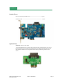
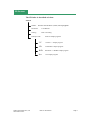
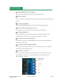
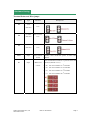
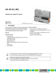
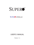
PEX-1X User Manual Soliton Technologies CO., LTD www.soliton.com.tw Soliton Technologies CO., LTD www.soliton.com.tw PEX-1X User Manual Page 1 CONTENTS 1. Introduction ………………………………………………………………………………………3 Overview …………………………………………………………………………………………3 Product Content …………………………………………………………………… …………….5 CD Content ……………………………………………………………………………………….6 2. System Functions ……………………………………………….……………………………….. 6 Hardware ……………………………………………………….………………………………... 7 System Functions ……………………………………………….………………………………... 8 Hardware Setting ……………………………………………….……………………………….... 9 LED Indicators ………………………………………………….………………………………... 10 3. Installation …………………………………………………….………………………………….11 Hardware installation ………………………………………….……………................................11 Operation Modes …………………………………………….…………………………………...12 Software Installation………………………………………….…………………………………...14 Folder and Files....…………………………………………………………………………………17 4. Operation…………………………………………………………………………………………..18 Windows Operating System……………………………………………………………………….17 Functions Setting…………………………………………………………………………………..19 Main Operation Windows………………………………………………………………………….21 Mass-production Mode…………………………………………………………………………….26 Engineering Mode………………………………………………………………………………….29 5. Current Calibration………………………………………………………………………………...30 6. System Setting……………………………………………………………………………………..31 7. Software Uninstall…………………………………………………………………………………33 8. Troubleshooting……………………………………………………………………………………34 9. Technical Support Contact…………………………………………………………………………35 Soliton Technologies CO., LTD www.soliton.com.tw PEX-1X User Manual Page 2 Introduction Overview PEX-1X - PCI Express Hot Swap Extender allow user to plug-in card of the PCI Express adapter into (PC) motherboard for testing. It suitable to be applied to any PC compatible to the 3rd generation PCI Express Bus. The excellent protection circuit can isolate any power and signals to avoid damage motherboard during testing and facilitate the hot-swap verifications with software control and function tests. It offers voltage(+3.3V, +12V) and current monitor function that it saves time and lab cost in product development and production testing. It provide the DLL (Dynamic Link Library) sources for software develop. It's suitable for PCI Express x1 / PCI Express x2 / PCI Express x4 / PCI Express e x8 / PCI Express x16 adapter card testing. Features Isolation Function can be performed by the built-in power switch for manual control or by software for remote control. Hot Swap Function can relieve engineers or testing people from turning off PC power and operation system, or repeatedly rebooting PC during the test or verification. By using this product and software provided, it allows engineering or testing people to perform hot-swap under system-on status, which will save the PC reboot time needed for card swapping, as a result, it will effectively shorten test time, increase production capacity and speed up the test. Applying the product’s auto-switch and insertion-to-auto-test-initiation function can simplify the test, and further more speed up the test as well as reduce human negligence, thus will meet the auto-test requirement. Production Function can provide protection against short-circuits or over voltage (over-current). When user test PCI Express adapter card that is the under unclear status or is malfunctioning this product will monitor test by supplying accurate DC power (+3.3V, +12V, +3.3VAUX) to ensure that the PCI Express adapter test specimen is working normally. Once there is a short circuit or abnormal voltage/current occurs, PEX-1X will immediately cut off power supplied to the slot to protect your PC and test specimen from being burnt. Audio function provides the built-in beeper and audio control program to inform operator by audio sound when test is completed or error occurred. Testers can then know whether the test is passed or a failure. Soliton Technologies CO., LTD www.soliton.com.tw PEX-1X User Manual Page 3 Current Measuring Function converts current consumption values of DUT at both +3.3V and +12V power rail into digital output. User can use software (Utility or DLL) to read directly the precise voltage and current values of DUT at +3.3V & +12V respectively through PCI Express Bus, and timely monitor DUT current consumption without any external instrument being engaged, it thus can remarkably reduce the expense on equipment and maintenance. Cable-less Control Function Previously a cable was needed to send control command if software control was applied. Now the PEX-1X makes it possible by the “Cable Less Control” function to control the device driver and the power of the DUT without any physical connection, making the installation easier on production floor. Specifications Compliant with PCI Express Specifications Rev. 3.0 12-bit Resolutions for Power Measurement +3.3V, +12V Power Monitor +3.3V, +12V, +3.3AUX External Power Input Support the PCI Express adapter card of the x1 , x2 , x4, x8, x16 lane Operating Temperature 0° ~ 55° C Input Power Ratings : +3.3VDC: +3V ~ +3.6V +12VDC: +11.5V ~ +12.5V +3.3DC VAUX: +3V ~ +3.6V Max Output Current Ratings : +3.3V: 3.0 A +12V: 500 mA +3.3VAUX: 375mA Soliton Technologies CO., LTD www.soliton.com.tw PEX-1X User Manual Page 4 Products Standard Parts: PEX-1X Hot Swap Extender card -------------------------------- 1 piece Installation CD ------------------------------------------------------- 1 piece PEX-1X Optional Parts PEX-1XL : PEX-1X Slot Riser To accommodate the heavy load of mass production that would cause the wear-out of the slot, this slot riser provides protection for the slot of PEX-1X card from wear-out and extend its duration. Use it together with the mass-production type DUT latch frame. PEX-1RS Soliton Technologies CO., LTD www.soliton.com.tw PEX-1X User Manual Page 5 CD Content The CD index is described as below : PEX-1X WinNT Windows 2K/XP/WIN7 (32 Bit) Install program Document User Manual Catalog PEX-1X catalog Example Code Soliton Technologies CO., LTD www.soliton.com.tw Index of sample programs VC Visual C++ sample program VB Visual Basic sample program BCB Borland C++ Builder sample program Net .Net sample program PEX-1X User Manual Page 6 Hardware PCI Express 1X Slot Power Indicator SW1 Power Switch Buzzer External Power Connector SW2 DIP Switch PEX-1X PCB Figure Soliton Technologies CO., LTD www.soliton.com.tw PEX-1X User Manual Page 7 System Functions Windows2000/XP/WIN7 (32-Bit) Support: Support Windows 2000/XP/Win7/Win8 Operating System (32 bit). Multi-Card Testing: Allow 1~4 PEX-1X cards applied concurrently at the same testing PC to test PCI Express products. DUT Card Enable/Disable: Execute Driver Enable/Disable function directly on PCI Express adapter card. Remote software control DUT power on/off: Use software to remotely control the power and signal switch of PEX-1X. On-board LED indicators: Provide LED indication of slot power and Go/No-Go state LED indication of the specimen at DUT end, making it easy for operators to judge the test result. Short-circuit & Over-current protection: Provide short-circuit & over-voltage protection that will protect the motherboard and DUT from being burnt out. On-board Current & Voltage Measurement: Provide current and voltage measurement, user can read the DUT power consumption rate directly by software utility or DLL. External Power Connector: Provide external power supply input to DUT. Allow user to switch power to external power supply at 3.3Aux, 3.3V or 12V for supplementary power. Please reference hardware setting in next page. External PW Connector 3.3Vaux 3.3V 12V GND Soliton Technologies CO., LTD www.soliton.com.tw PEX-1X User Manual Page 8 Hardware Setting Terminal Points and Wire-jumps: Terminal P4 Type +12V Selection P5 P3 SW1 Function Bus or External Power +3.3Vaux Bus or External Selection Power +3.3V Bus or External Selection Power Input Descriptions Power control Manually turns on/off the power of DUT Slot switch (default). Works with hardware/software to perform multi-card S1 Input Multi-card control operations (default: S1=11) S1=00 Set control address as 1st Extender S1=01 Set control address as 2nd Extender S1=10 Set control address as 3rd Extender S1=11 Soliton Technologies CO., LTD www.soliton.com.tw Set control address as 4th Extender PEX-1X User Manual Page 9 LED Indicators LED Mark D1 Description Indicate the +3.3Vaux power status at DUT slot. +3.3VAux ON: +3.3Vaux power is under supply already. OFF: no +3.3Vaux power supplied to DUT slot or short circuit occurs. D2 Indicate the +12V power status at DUT slot. +12V ON: +12V power is under supply already. OFF: no +12V power supplied to DUT slot or short circuit occurs. D3 Indicate the +3.3V power status at DUT slot. +3.3V ON: +3.3V power is under supply already. OFF: no +3.3V power supplied to DUT slot or short circuit occurs. D5 D6 Go NoGo Use program to control LED ON (light up) to indicate the DUT test result is PASS. Use program to control LED ON (light up) to indicate the DUT test result is FAIL. Soliton Technologies CO., LTD www.soliton.com.tw PEX-1X User Manual Page10 XHardware Installation Before installing PEX-1X, please turn off PC and unplug the AC power cable and perform the following installation step by step. 1. Install the PEX-1XL riser onto PEX-1X slot 2. Open the PC box cover. 3. Take out the PEX-1X Extender from the anti-static-electricity bag and insert it into any PCI Express x 16 slot on motherboard 4. Use screws to secure the card to the PC box after the PEX-1X Extender is plugged in place. 5. Insert the PCIex1 DUT to the PEX-1X. 6. Plug the AC power cable to plug seat and turn on PC. 7. PC system will automatically detect the PCI express x16 DUT and install DUT driver. 8. Ensure that DUT works normally; now the hardware installation is complete. Soliton Technologies CO., LTD www.soliton.com.tw PEX-1X User Manual Page11 Operation modes PEX-1X is very powerful which provides many modes for selection as described below. 1. Standard Control Mode In this mode, no PEX-1X software or driver is install required, users just use and control the PEX-1X manually. We recommend user to use this mode to test first, after it works then move to control software installation. The operation procedures are described below. (a) After the hardware is installed, click to open Windows Device Manager to verify that the DUT driver works properly. (b) Use DUT test program to verify the card; when finished, go to the Device Manger and manually disable the DUT driver. Illustration below shows a network card applied as the DUT, users should select the actual DUT driver of their own and disable it. DUT (c) When a red cross-mark appears on the DUT icon, it means the DUT driver is disabled. Push the PEX-1X main power switch to turn off the DUT power. Ensure that the power indicator on PEX-1X card is off and then swap another DUT without turning off PC. DUT is disabled. (d) After DUT is exchanged, push the switch again to turn on the PEX-1X main power to activate the DUT power, power indicator at the PEX-1X card should light on to indicate the DUT is powered. If the DUT is not powered, the DUT might be short-circuited or over current occurred, please fix the problem before performing next step. (e) When power is activated normally, go to Device Manager and enable the DUT driver. If the DUT works normally, the red cross-mark on the icon should disappear; system is now restored to the initial DUT status. Activate driver Soliton Technologies CO., LTD www.soliton.com.tw PEX-1X User Manual Page12 2. Software control mode Use PEX-1X software utility to perform the above basic operation/control functions and advanced DUT voltage /current measurement. The simple and diverse interface facilitates the operation for both engineers and operators. For details, please refer to next chapter for software installation and operation. 3. Program control mode If users want to integrate PEX-1X’s control functions into their production test program, just used dynamic linking library (DLL). The source code of sample program is provided in CD_ROM. To develop the production test programs under VC, VB or Builder C++ environment, please refer to the following documents: Document\DLL_Manual\ PEM-1X Dll v4.x.pdf Soliton Technologies CO., LTD www.soliton.com.tw PEX-1X User Manual Page13 Software Installation Note: Before installing PEX-1X software, please ensure that the DUT device driver has been installed properly and works normally. Installation (Windows version): Perform the following step by step to install the PEX-1X control utility. 1. Insert the PEX-1X CD to the CD drive, and go to PEX-1X\WinNT\Utility directory. 2. For WinXP /Vista/Win7 (32-Bit) /Win8 (32-Bit) system please select PCIE NT Vx.x.exe and double click to execute the install program. The Welcome screen will appear.. 3. Click Next to start installation, or Cancel to abort. 4. Again, ensure that the PEX-1X Card has been installed in PC correctly. On the other hand, if the DUT isn’t properly and correctly installed, system will not be able to find the related hardware during the installation and would be unable to setup and allocate the correct configuration data, consequently it causes failure to install the program. If the hardware isn’t properly installed, cancel the installation first. After correct hardware status is confirmed, resume the installation. Soliton Technologies CO., LTD www.soliton.com.tw PEX-1X User Manual Page14 5. When prompted the path that program is to be installed, click Next (※do not change the path location). 6. Select “Typical”, and click Next . Soliton Technologies CO., LTD www.soliton.com.tw PEX-1X User Manual Page15 7. When the following dialog box appears; click “OK” to go to next step. 8. When the following error message dialog box appears, ignore it by clicking “OK”. 9. When the following dialog box appears to indicate that the device driver has been successfully installed, click “OK”. 10. When the dialog box shown as below, it means the installation is completed, click “OK” to reboot PC. 11. After the program is installed, system will create a shortcut of PCIEU application program icon on desktop. 12. To execute the PEX-1X utility program, click the shortcut icon on your PC desktop, or go to the default path (C:\Program Files\Soliton\PCIE Extender\Utility\PCIEU.exe). Click to run PCIEU.exe. Soliton Technologies CO., LTD www.soliton.com.tw PEX-1X User Manual Page16 Folder and Files After the hardware and software both are installed, system will create following folder into your hard drive. The actual path will vary according to the user’s setting. Default installation path is illustrated in this manual as below. The default installation path is: C:\Program Files\Soliton\PCIE Extender\ Document Folder: User Manual Debug Tool Folder: Debug Tool Program Utility Folder: Windows version of control software Note: To integrate the PEX-1X control functions into production test program, user can call the dynamic linking Library (DLL). The source code of sample program is provided in CD-ROM. Test programs can be developing under VC, VB or Builder C++ environment. Please refer to the following documents for more details of DLL. Document\DLL_Manual\PEM-1X Dll v4.x.pdf Install the control program sample software: 1. Insert the PEX-1X CD into your CD drive and change folder to PEX-1X\Sample_Code directory. 2. Directly copy the sample program folder in the CD into your hard drive. Before modifying the program, make sure program developing software, such as VC, VB or BCB has been installed properly. Then, open the Project which just copy to hard drive of the sample’s source codes, re-compile and link the source code to generate the execution file. Soliton Technologies CO., LTD www.soliton.com.tw PEX-1X User Manual Page17 Usage and Operation Windows version: Important Message Make sure the Golden Unit is plugged for the first time of software installed or every time you reboot PC, also make sure all the DUT functions are working normally. The PEX-1X control software not only provides engineering mode, it also provides mass production mode; various operation and setting windows are illustrated as below: Select device under test Main OP. Window and Mass production Auto Mode Engineering Manual Mode Configuration & Inspecting unit Soliton Technologies CO., LTD www.soliton.com.tw PEX-1X User Manual Page18 1. INITATE PEX-1X After the application software is installed properly, system will create a shortcut icon on desktop, click to open the control program. If no such icon can be found on desktop, please launch the program at the path defined below: C:\Program Files\Soliton\PCIE Extender\Utility\PCIEU.exe 2. DUT SELECT PANEL When execute the PCIEU.exe for the first time, or applying it to different types of DUT, Fig 1 as below will appear. The main purpose of the interface is to list all interface devices in system for users to select corresponding DUT inserted on the PEX-1X. Be sure to select match DUT, otherwise it might cause software malfunction or PC crash. After setting is completed, main operation window dialog will be loaded automatically. (F) (A) (B) (C) (D) (G) (E) (Fig 1) 2-1 User Interface Introduction: (A) LED display: Indicate the DUT configuration status. If configuration is not set yet or is incorrect, the respective indicator will flash yellow and message prompts “Please Select Your Device”. If the setting is correct, the indicator will turn to green and message prompts “PEX-1X Addr [XX] has setting success!”. (B) Device information: Displays the information of selected DUT, it includes DUT vendor ID, sub vendor ID, Device ID, bus number, device number and sub system ID for identify the DUT. (C) Interface device table: displays the interface information of all devices installed on the motherboard, applied for user to select DUT. Device being clicked will show the related information on (b) edit box for user’s check. (D) Set button: After confirmed the DUT select on the PEX-1X, press SET button to save current configuration data into system, then it can work with the PEX-1X application program to perform hot swapping or DUT debugging. Soliton Technologies CO., LTD www.soliton.com.tw PEX-1X User Manual Page19 (E) Close button: closes this device selection window and enter the main control window of the PEX-1X application software. (F) Reselect DUT Device: To reselect DUT device please select the menu bar of Options → Reselect DUT Device. (G) PEX-1XAddr: displays and selects activate PEX-1X address setting. When multi-card control is used, each of PEX-1X has to set unique address (00~03) by change S1 dial switch. 2-2 Setting Procedures: (1) Select the DUT inserted on PEX-1X from the interface device list in Fig 2, the selected device will be highlighted. (2) Confirm the data correctness of the selected device, for example, the information of Vendor ID and Device ID. (3) Click Set (4) Click Close to complete the setting and save it, shown in Fig 2. to finish the setting and enter the main control window. (Fig 2) 2-3 Notes : Before click Set button, please double confirm the setting information of selected DUT. If it is incorrect, click to select and make setting on it once again, otherwise the DUT and PEX-1X card won’t be controlled by the software as they should be, which will result in the software malfunction and system crash. If the device selection window can not be closed after clicking Close button, this means the software already detected certain errors on the setting; please check following items. (1) Is DUT power of PEX-1X card at on state? (2) Is DUT inserted into PEX-1X card slot? Soliton Technologies CO., LTD www.soliton.com.tw PEX-1X User Manual Page20 3. MAIN OPERATION WINDOW As displayed in Fig 3, the main operation dialog box provides the control of card hot swapping, debugging and the status information. (A) (B) (H) (C) (G) (B) (E) (D) (F) (Fig 3) 3-1 Operation Window Introduction (A) MENU BAR (Ⅰ) Driver pull-down menu Click the “Driver” from main dialog box menu bar for control DUT device driver Enable, Disable, Refresh and Restart. Disable DUT driver Enable DUT driver Refresh DUT driver Restart DUT driver (Fig 4) (Ⅱ) Options pull-down menu Options pull-down menu provides many functions allow users to set detail control tasks. The options menu is shown in Fig 5. (Fig 5) Soliton Technologies CO., LTD www.soliton.com.tw PEX-1X User Manual Page21 Reselect DUT Device : Opens the DUT device selection window as shown in Fig 6. (Fig 6) Settings : Opens the PEX-1X setting window as shown in Fig 7. (Fig 7) Run Current Calibration:Apply to calibrate the PEX-1X measurement function, please refer to the appendix for detail. Reselect Control Mode : Manual Mode and Auto Mode are available for users’ selection, illustrated as below. Users can switch manual mode for engineering or auto mode for mass-production. Manual Mode: Open the engineering manual control mode. Auto Mode: Open the auto mass-production control mode. Manual control mode Mass-production control mode (Fig 8) Soliton Technologies CO., LTD www.soliton.com.tw PEX-1X User Manual (Fig 9) Page22 (Ⅲ) Help pull-down menu For check current software utility and DLL library version at Help menu. (Fig 10) Check PETs(PEMDLL.dll) version (Fig 11) (B) ADDRESS/POWER STATUS DISPLAY AREA Address: Display and activate which PEX-1X card is under control. Shows which PEX-1X card being selected or in use, ADDR in the operation window will display (00 ~ 03). Power xx: Displays the power status of PEX-1X card Indicator in red means the DUT slot power is on. Indicator in gray means the DUT slot power is off. GO : Displays the result of DUT card hot swapping. If the result of card swapping is normal, green indicator will light up. If the result of card swapping procedure is abnormal, indicator will grey. NG : Displays the result of DUT card hot swapping. If result of card swapping is abnormal, yellow indicator will light up. If the result of card swapping procedure is normal, grey indicator will grow. (C) SHORT-CIRCUIT STATUS DISPLAY AREA In normal operation, the Short Status displays in black text, whereas the 12V, 3.3V or 3.3Vaux LED indicators are in green status. Soliton Technologies CO., LTD www.soliton.com.tw PEX-1X User Manual Page23 When DUT short-circuit is occurred, the Short Status will show in red text, and LED indicator will flashes in yellow, this means the respective power circuit is short-circuited or over-current. In this case, change another DUT and test again. Figure 12 is an example of 3.3V shot-circuit. (Fig 12) (D) TEXT MESSAGE DISPLAY AREA System will shows all the control, error and activity messages in this area. (E) CONTROL BUTTON AREA Actived It can switch and display which PEX-1X card is under control. Swap Card While under auto mode, whenever clicking this button software will execute the following actions in sequence to swap another DUT. Driver Disable → Power off Hot key: (Ctrl + F1) Restore While in auto mass-production mode, whenever clicking the “Restore” button, software will execute the following actions in sequence. After DUT is being swapped, click restore for DUT back to initial state. Power On → Driver Enable Hot key: (Ctrl + F2 ) Read VI Read V_I measurement values While clicking this button, screen will auto open and display the V_I measurement window as shown in Fig 15, displayed data will be read and updated every 2 seconds. To disable the V_I measurement function, click the “Stop VI” button. To enable the V_I measurement function, click the “Read VI” button. Soliton Technologies CO., LTD www.soliton.com.tw PEX-1X User Manual Page24 (Fig 15) Driver Disable Disable the DUT (driver) device (available in manual mode). Driver Enable Enable the DUT (driver) device (available in manual mode). Power Off Turn off PEX-1X card slot power (available in manual mode). Power On Turn on PEX-1X card slot power (available in manual mode). Run Prog While in auto mode, click the “Run Prog” button to launch the test program which user been set in system setting dialog box. (F) Refresh DUT Driver Refresh DUT Driver. STATUS BAR Display the PEX-1X card being initiated and its address (0~3), also the information of DUT Vendor ID and Device ID. If the Vendor ID or Device ID does not match with DUT, users can click Options from menu bar and select Reselect DUT Device to list all system devices information for re-select DUT. (G) DUT DEVICE DRIVER STATUS While the DUT swapping users can monitor the DUT device driver status in this bar. If the DUT icon with red cross-mark means device driver is disable. Normally PEX-1X software will auto enable DUT driver after DUT swapped in production mode. Be note the DUT driver should be enable before running the function test. In some cases exclamation mark (!) might be occurred on driver icon, please check the connection between DUT and slot or DUT hardware may not works. (H) VOLTAGE / CURRENT DISPLAY AREA Shows the DUT +3.3V and +12V two power rails of voltage & current reading that measured from PEX-1X. It is very useful to check the current reading after DUT power on, since any hardware problems will caused abnormal current reading. The refresh rate of reading is 2 seconds. Soliton Technologies CO., LTD www.soliton.com.tw PEX-1X User Manual Page25 3-2 Operation procedures of mass-production mode: (3) (2) (5) (4) (Fig 16) (1) After setting is complete, run PCIEU.exe and screen will appear as shown in Fig 16. Software will detect all the PEX-1X cards on the PC motherboard, and indicates the readiness by (red) POWER indicator and (green) GO indicator. System can control 4 PEX-1X cards at most concurrently for test or application. When multiple PEX-1X cards are applied, each card should set in unique address by S1 dial-switch, S1 dial-switch address range are 00, 01, 10 to 11. Once you enter the main operation window, verify the following items: (1) (2) The DUT data such as Vendor ID and Device ID. The power LED indicator in red means that the slot power is ON. And if the Driver LED indicator is in red, it means the DUT Device Driver is in ready status. (3) If 12V, 3.3V & 3.3Vaux short-circuit indicator is in green, it means that power supply is normal. And if all displays are normal, use the following buttons to control DUT. (4) Click Swap Card button to swap DUT. The software will close the DUT driver and turn off the power. After the Power LED indicator from on goes off, operator then can remove DUT and replace with a new one. Operator also can use hot key to operate it by keyboard. Hot-key: (Ctrl + F1) (5) When the DUT is replaced, click the Restore button to turn on the power and enable the DUT driver. If all indicators are normal, perform the DUT test program. Otherwise, the DUT might be defective; change it by another new card. Restore Hot key: (Ctrl + F2 ) Soliton Technologies CO., LTD www.soliton.com.tw PEX-1X User Manual Page26 (6) PEX-1X will shows the messages at text display area for current activity status. Any normal or abnormal messages will be displayed in this area. Swap Card Æ Replace DUT Æ Restore Æ Verify DUT FunctionsÆ Test Completed Status display of engineering operation mode : (a) State before swapping Card (b) After Swap Card button clicked Replace New DUT (c) After DUT replaced, click Restore Soliton Technologies CO., LTD www.soliton.com.tw (d) Card-swapping successful, start testing PEX-1X User Manual Page27 (7) Errors that might occur after card is changed : Error light & message (Fig 17) If an error message shown in above figure 17 after card is replaced, it means the card swapping has error. The PEX-1X software has DUT verify capability, therefore it will bring error message to the text message area. Please correct the error and click the Restore button once again, window will be restored to the screen that card being successfully swapped. The related error messages are described below. 1. PEX-1X[xx] No DUT Card Plug in No DUT is plug in PEX-1X, probably DUT isn’t inserted please re-insert it. 2. "Check DUT Device VID DID Error By PEX-1X [xx] !" The new DUT does not match the VID, DID data originally saved. Probably DUT isn’t inserted or is malfunctioning, re-insert or replace it. 3. "Check DUT Device SVID SID Error By PEX-1X [xx] !" The replaced DUT does not match the originally saved SVID, SDID data. Probably DUT isn’t inserted properly or is malfunctioning; re-insert or replace it. 4. "Failed To PEX-1X [xx] Power On !" The power-on function of the PEX-1X is abnormal. 5. "Failed To PEX-1X [xx] Power Off !" The power off function of the PEX-1X is abnormal. 6. "Failed To Disable DUT Device Driver By PEX-1X [xx]"! Error detected while the PEX-1X disable the DUT driver. 7. "Failed To Enable DUT Device Driver By PEX-1X [xx]" Error detected while the PEX-1X enable the DUT driver. Soliton Technologies CO., LTD www.soliton.com.tw PEX-1X User Manual Page28 3-3 Operation procedures of engineering mode : To apply multiple PEX-1X cards, it is necessary to set up each card to different dial switch S1, the order is from 00, 01, 10 to 11. After entering the operation window normally, check the following items (a) DUT data, such as Vendor ID and Device ID. (b) If the Power LED indicator in red, it means the slot power is ON. (c) If the Driver LED indicator in red, it means the driver is enabled already. (d) Check if the 12V, 3.3V & 3.3Vaux short-circuit indicators are all in green at software panel, which represents all power rails are in normal state. (e) Driver Disable Disable the DUT device driver. (f) Driver Enable Enable the DUT device driver. (g) Power Off Turn off the DUT slot power at PEX-1X card. (h) Power On Turn on the DUT slot power at PEX-1X card. Driver Disable Æ Power Off Æ Replace DUTÆ Power ON Æ Æ Driver Enable Æ Verify DUT Æ DUT Test Completed Soliton Technologies CO., LTD www.soliton.com.tw PEX-1X User Manual Page29 Current Calibration To read the DUT current consumption more precisely, user can perform the current calibration described below. Before doing so, remove DUT and the extended cable on the PEX-1X slot card, it is because the calibration program should be performed in non-loaded mode. Operation procedures of current calibration : (a) Click the “Run Current Calibration” from menu bar. (b) When the dialog box shown as below, please remove DUT from PEX-1X and press “OK”. (c) Program now starts to calibrate current. When finished, the dialog box shown as below. Options for current calibration: After calibration system will store calibration factor into hard drive, users can determine to use this factor or not by select Enable / Disable of “Use IcalFactor” in menu bar. Also this factor can be deleted by click “Delete IcalFactor”. Enable factor calculation Disable factor calculation Set factor to zero Soliton Technologies CO., LTD www.soliton.com.tw PEX-1X User Manual Page30 System Setting SETTING DIALOG (configuration setting of PEX-1X card): Click Options from menu bar and select Setting , the Setting Dialog shown below will appear. It displays the saved configuration register of PCI DUT for review, comparison and selection for the test method and the process of DUT. After the main program is proformed, it will automatically detect the configuration setting to make related application and verification test. This dialog box also allows users to set the DUT test program setting; if there is no test software, no data input will be required, just keep it blank. Enable Beep Function: Check to enable the alarm function, or leave it blank to disable beep function. One long beep sound indicates the PEX-1X is abnormal. Two short beep sound indicates the PEX-1X is normal. Test Program Auto Execution Mode: If selected, system is set to auto control mode, which means system will auto run the DUT test program whenever the card-swap procedure is complete. Leave it unchecked to disable the test program link control function. Check Device VID DID: If selected, it means every time when the card is swapped, program will auto check if the saved settings of PCI configuration match that of the replaced card. This will greatly help to screen the DUT at beginning of testing, the production capability can then be boosted. (System default is set to on. It is recommended to use this function.) Check Device SVID SID: If selected, it means every time when the card is swapped, program will auto check if the saved settings of PCI configuration is match with the replaced card. This will greatly help to screen the DUT at beginning of testing, the production capability can then be boosted. (System default is set to on. It is recommended to use this function.) Soliton Technologies CO., LTD www.soliton.com.tw PEX-1X User Manual Page31 Wait Time After DUT Plug-in After activating the auto card-insertion trigger function, to avoid error users can set certain period of time for waiting so that the main power of the PEX-1X will be automatically turned on after the card-insertion is fully performed and stabilized. Note: Before adjust this parameter, select the “Enable Card Plug Function For Auto_Mode” option first (system default is: 3000 ms). Wait Time Before Test Program Execution This parameter allows users to set a certain period of time for waiting after the DUT driver has been successfully initiated and before the test program is activated. Waiting time is necessary because after the DUT driver is activated, it needs some time to execute the test program. Condition for setting up this waiting time is no error occurs during the test program is being performed and no system crash occurs. Waiting time should be as short as possible. Note: Before adjust this parameter, select the “Auto Test Program Running Mode” option first (system default is: 1000 ms). DUT Driver Enable Delay Time This parameter allows users to set a certain period of time for delay after the DUT driver is successfully initiated. Delay time is necessary for ensuring the DUT is fully enabled for some DUTs need longer time to initiate. DUT Driver Disable Delay Time This parameter allows users to set a certain period of time for delay after the DUT driver is fully disabled for some DUTs need longer time to stop. Test Program Filename: It displays the folder, path location and name of the DUT test program being set. Brows : Set the folder, path location and name of the DUT test program by browse. Enable Test Function: Select this option to activate the connection capability of the DUT test program. If it is unchecked, system will clear the folder path and name of the DUT test program. Test : Perform the DUT test program been linked. Save : Save the parameter data been set or modified on the Setting Dialog, and close the Setting Dialog configuration window. Close : Close the Setting Dialog configuration window without saving. . Default : Reset all values to factory default. Soliton Technologies CO., LTD www.soliton.com.tw PEX-1X User Manual Page32 Software Uninstall To uninstall the PEX-1X application software, please open Control PanelÆ Add/Remove Program to run PCIEU; windows shown below will appear. Click “Remove” and “Next”, and click “YES” to start the uninstall process. When finished, reboot your PC. 3 1 2 Soliton Technologies CO., LTD www.soliton.com.tw PEX-1X User Manual Page33 Notes and Troubleshooting Notes: 1. Before installing the application program, ensure that the PEX-1X card is properly installed in your PC already. If the PEX-1X is not properly installed, system won’t be able to set up configuration data properly during the installation. It is because no related hardware can be found, and that would cause malfunction of the program. If this occurs, use the uninstall software to remove the application program. Make sure the hardware is installed properly, then re-install the application program. 2. If the Driver Disable or Driver Enable buttons are used during the test process, do not perform next step until all related actions are completed, otherwise, it would cause PC crash. 3. (Windows) software wise, when multiple PEX-1X cards are used concurrently in one PC, to shift the software control from one PEX-1X card to anther, make sure that the controlled PEX-1X card is at Power On status, and the PCI driver on the card is under normal and ready status. 4. While inserting DUT to the PEX-1X card, if beeper on the PEX-1X makes three consecutive long beeps for warning and the power indicator is off, it means that short-circuit is detected and the PEX-1X card has performed auto power-shutdown protection. In this case, change another card to continue to use the PEX-1X. 5. Troubleshooting : 1. 2. If the error message “No PCIE Extender Card Found on System!” shows up when launch PCIEU.exe, please check below status. a. Is PEX-1X extender card installed in PC? b. Is the motherboard chipset support by PEX-1X firmware? Check the updated information on our web site. If message “No Card Found on System” appears after running the PCIEU.exe and buttons on the operation window are disable, this means that the hardware/software of the PEX-1X card isn’t installed and set up properly, do the following: (1) Make sure the Mini PCIe DUT is inserted properly on the PEX-1X card and the driver is installed correctly. (2) When using multi-card control mode, make sure the address of S1 DIP switch on all PEX-1X cards is unique. 3. If DUT is unable to function after PC is booted or system is rebooted, go to Control PanelÆSystem Device ManagerÆSystem Devices to check if the DUT driver is disabled. If it is disabled, manually enable it. 4. If normal operation dialog box cannot be displayed after PEX-1X.exe is executed, close resident programs such as antivirus or other software temporarily. Soliton Technologies CO., LTD www.soliton.com.tw PEX-1X User Manual Page34 Technical Support For any technical problem regarding the PEX-1X, please visit our website first. http://www.soliton.com.tw. For further information, please reach us at: Phone:+886(0)3-656-6996 Fax :+886(0)3-656-6883 Email : [email protected] Soliton Technologies CO., LTD www.soliton.com.tw PEX-1X User Manual Page35