1
TP_ESM_8 Board (Arduino-Compatible)
USER’S MANUAL
INDEX
Ver.02 Updated 2013/4/17
1
INTRODUCTION
1
1.1
SET-UP
1.1
2
SET IP
2
2.1
Automatic Network Configuration using DHCP
2.1
2.2
Network Configuration using a Static IP Address
2.2
2.3
Set IP step-by-step
2.3
2.3.1
Network Parameter Descriptions
4
SET WEB
4
4.1
Mode
4.1
4.2
Type
4.2
4.3
Tag
4.3
4.4
Message
4.4
5
EVENT NOTIFICATION
5
5.1
Email Notification
5.1
5.1.1
Find a SMTP Server
5.1.1
5.1.2
Go to Email tag
5.1.2
5.1.3
Set Basic Email (taking GMX for example)
5.1.3
5.1.4
Add Email recipients of Email notification
5.1.4
5.1.5
Set Email recipients
5.1.5
5.2
SMS notification
5.2
5.2.1
Find a SMS provider
5.2.1
5.2.2
SMS-1 step-by-step
5.2.2
5.2.3
SMS-2 notification format
5.2.3
5.2.4
SMS-2 step-by-step
5.2.4
5.3
Web Display
5.3
5.3.1
View of real-time monitored 8 D/I status on the web page
5.3.1
5.3.2
View of real-time monitored 8 D/I status
5.3.2
5.3.3
A D/I is triggered
5.3.3
5.3.4
Wiring Connection (for D/I trigger)
5.3.4
5.3.5
ASCII data as received from UART interface
5.3.5
5.3.6
Standard format of ASCII data
5.3.6
5.3.7
More examples of ASCII data
5.3.7
5.3.8
Go to web-page view of ASCII data
5.3.8
6
UPGRADE
6
TP_ESM_8 Board (Arduino-Compatible)
1 INTRODUCTION
The TP_ESMS_8 Board is completely programmable from the menus of application software
(TP_ESMS_8.exe, as provided by TOPOINT CORP). This makes it easy to set up program
and utilize the features of the board device. The pages can be accessed by executable
application software and then a click of the SEARCH button to access the device (see the
Network Configuration section in Chapter 2.2). The menu tags as appeared at the top of
screen will help you locate specific programming parameters and features. The Summary
screen is your main page to view the current status of all monitored 8 digital inputs (D/I) status.
1.1 SET-UP
The TP-ESMS-8 application software provides access to several menus dealing with the
configuration. They are divided into the following menu tags: Upgrade, SetIP, SetWeb,
SetEmail (inclusive of setting SMS). The description of each tag and associated configurable
parameters are described below.
TP_ESM_8 Board (Arduino-Compatible)
2 SET IP
The SetIP settings are used to describe and configure general properties of the network. The
information as entered into the unit fields of NAME, MAC, IP, MASK, GATEWAY, DNS, HTTP
PORT, UDP PORT, NAME will appear in the front of SetIP page. Use these to help identify the
unit and location so that when any one of D/I is triggered and you’ll know exactly where the
trigger occurs.
2.1 Automatic Network Configuration using DHCP:
For an easier set-up, the interface provides the selection of DHCP enable. If your network
supports DHCP, i.e. in the conjunctional use with a Network Router, then simply plug the
Ethernet jack into the TP_ESMS_8 unit and turn the unit on. Allow the unit to finish booting-up
(a few seconds). By factory default, the selection of DHCP enable has always been checked.
Only when DHCP enable has been checked is able to display these related parameters
automatically. Leaving DHCP unchecked will lead user to modify those parameters manually.
As long as user’s network supports DHCP, user is strongly advised to click DHCP enable so
that a detected TP_ESMS_8 will be displayed showing its IP address and MAC address
(TP_ESMS_8 hardware serial number) accordingly. A double-click on the TP_ESMS_8 in the
top list and then your browser will open to the status viewing page of monitored 8 D/I.
2.2 Network Configuration using a Static IP Address:
If your network does not support DHCP then your unit will set its IP address to 192.168.1.250
by factory default. This address should be temporarily set. However, leaving this address as
the factory default could result in net-working conflicts if another TP_ESMS_8 unit is added to
your network.
It’s highly recommended that you consult network configurations and settings changes with
your Network Administrator if you check Modify and abandon the use of DHCP Enable. To this
end, user would like to switch over to the proper settings manually, for example, for the input of
a permanent fixed IP address instead.
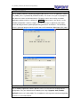
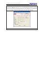
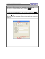
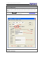
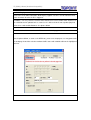
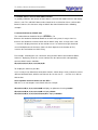
2.3 Set IP step-by-step
Step1:
Just execute TP_ESMS_8.exe application software and it enters the front page as the
following photo shows, then followed by a click SetIP tag on the top row in order to go into the
main network configuration page. See the following picture. If your network supports DHCP
then simply plug the network jack into the TP_ESMS_8 RJ45 Ethernet port and turn it on.
Allow the unit to finish booting up (for a few seconds until the RUN led indicator starts to flash
steadily, which is similar to heartbeat pulse. Only at this moment on, user concludes that the
TP_ESMS_8 unit has started to function.
TP_ESM_8 Board (Arduino-Compatible)
TP_ESM_8 Board (Arduino-Compatible)
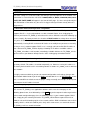
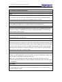
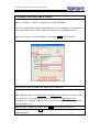
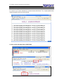
Step2 : Press Search button to access available TP_WEB_8 unit over the Ethernet network.
After a few moments, the detected unit is displayed on the topmost position, i.e., see the row of
AR-145 192.168.0.1 TP_ESMS8V1.6….
TP_ESM_8 Board (Arduino-Compatible)
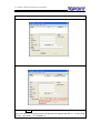
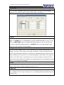
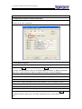
Step3: Upon the unit; for example, AR_145, has been displayed in the top row, user may
proceed with a single click right on AR_145 (see the photo below for the blue bar), and related
parameters that have been generated from board unit is to be displayed (see the photo below
for the fields of MAC, IP, MASK, GATEWAY, DNS, HTTP PORT, UDP PORT, etc).
TP_ESM_8 Board (Arduino-Compatible)
2.3.1 Network Parameter Descriptions
DHCP
Enabling this option means that the TP_ESMS_8 unit will automatically obtain an IP address
on the network using Dynamic Host Configuration Protocol (DHCP). Disabling this option
means that you will have to configure the network parameters manually.
MAC
This is the Media Access Control address which, in general terms, is the hardware address for
the TP_ESMS_8 unit port. There is a unique address for all network devices.
IP
This is the entry field for manually configuring the IP address of TP_ESMS_8 unit on your
network. This address is provided by you or your network administrator. It is formatted as a
standard dotted decimal number.
MASK
This is the subnet mask which distinguishes the portion of the IP address that is the network ID
from the portion that is the station ID.
GATEWAY
A TCP/IP network must have a gateway to communicate beyond the LAN identified by the
network ID. A gateway is a computer or router that is connected to two different networks and
can move TCP/IP data from one to the other. If your TCP/IP network has more than one LAN
or if you are connecting to the Internet, you will need to know the IP address of the gateway
that will transfer TCP/IP data in and out of your LAN. A single LAN that is not connected to
other LANs does not require a gateway setting.
DNS
It stands for Domain Name System and the DNS translates Internet domain and host names to
IP addresses. DNS automatically converts the names we type in our Web browser address bar
to the IP addresses of Web servers hosting those sites.
Note: if user is in conjunctional use with a network router under a permanent IP, he is
reminded to check if the DNS fields as displayed both in the board unit and in the router should
be input properly.
HTTP PORT
Allows section of the port number that the web server will use to host the web page. Default is
80. If changed from the default you must include the port number in your browser address
(example: 192.168.1.250:85)
TP_ESM_8 Board (Arduino-Compatible)
4 SET WEB
User may edit the notification contents of web which will be viewed on the web-enabled
browser in case any one of 8 D/I is trigger (in other words, event occurs)
4.1 Mode
There are 3 modes available which are ALARM, DISABLE and INDICATING for notification
options. In ALARM mode, TP_ESMS Board sends Email/ SMS notification as soon as event
occurs. In INDICATING mode, the hardware board just displays its status on the web view
instead of sending Email/SMS notification. In DISABLE mode, the hardware board simply
ignores D/I status regardless of what happens.
4.2 Type
There are 2 types available, which are NC (Normally Closed) and NO (Normally Open). For
example, if the D/I 1 has been preset to NC type, and once D/I 1 input is made to NO (D/I 1
input is connected to ground or lower-level voltage), the hardware board just regards that D/I 1
input as abnormal, thus, generates an event correspondingly. In other words, D/I is triggered.
Likewise, if the D/I has been set to NO type, and as soon as D/I input is made to NC (D/I 1
input is connected to a higher-level voltage), the hardware board receives that abnormal signal
(from D/I 1) and responds accordingly.
4.3 Tag
The configurable contents of these entry fields will be displayed on the web view, showing the
real-time 8 D/I statuses. Maximum input of characters is 20
4.4 Message
The configurable contents of these entry fields will be displayed on user’s email content and/or
on his cellphone short message as long as there is an incoming notification. Maximum input of
character is 40
TP_ESM_8 Board (Arduino-Compatible)
5 EVENT NOTIFICATION
TP_ESMS_8 Board provides two (2) mechanisms of event notification---Email, SMS (also
known as short message). Other than that, the real-time view of monitored D/I status can be
viewed via a web-enabled browser.
5.1 Email Notification
5.1.1 Find a SMTP Server
User is required to find at least a suitable SMTP server(s) from a reliable email service
provider(s) before setting up following parameters. A SMTP service provider is able to send
user’s every outgoing email.
Taking a renowned email service provider gmx.com for example,
its mail SMTP server address: smtp.gmx.com
GMX Mail SMTP user name: Your full GMX Mail email address ("[email protected]", for
instance)
GMX Mail SMTP password: Your GMX Mail password
GMX Mail SMTP TCP port: 25
GMX Mail SMTP TLS/SSL required: no
Note: If using GMX as a SMTP provider, user is noted of the consistency in the entry fields of
E-Mail from and Account Name . In short, fill in your full GMX Mail email address both in the
E-mail from and Account Name. The discrepancy in these 2 fields may result in sending error
of outgoing emails.
User can be referred to other suggested SMTP service providers, signing up for their SMTP
membership in order to get a set of approved Username and Password
In case user has an Ethernet network in the locality. Mostly, that Internet Service Provider
(ISP) provides SMTP service for free.
SMTP Service Provider
SMTP Mail Server
TCP Port
turbo-smtp.com
25
smtpcorp.com
25
smtp.sendgrid.net
25
TP_ESM_8 Board (Arduino-Compatible)
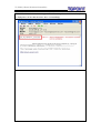
5.1.2 Go to Email tag
Step1: As soon as the unit AR_145 has been detected (see 2.3 SetIP step-by-step)
successfully, user may proceed to Email setting by clicking the SetEmail tag
Note: Check the IP address and Port fields as shown at the upmost 2 rows (in this case below,
it is IP:192.168.0.1/ Port:4660) should be as same as the ones as displayed in the SepIP tag.
Step2: Press Read button to retrieve existing setting. Note: the entry fields of Email From/
SMTP Server/ SMTP Port/ Authentication/ Account Name/ Password are all in the blank in the
first time use.
TP_ESM_8 Board (Arduino-Compatible)
5.1.3 Set Basic Email (taking GMX for example)
After user has successfully applied for GMX mail, for example, to have a full GMX Mail email
address, password, he is able to set parameters of email notification
Note: The example below is only based on GMX mail. Other email/SMTP service providers are
likely to have different rules. Please always consult with your email/SMTP provider.
Step1: This tag makes user to set outgoing emails. Go to Basic tag by a click on it.
Step2: Fill in the fields of E-Mail From, SMTP Server, SMTP Port
Step3: Fill in the fields of Account Name, Password, followed by a check on Authentication.
Note: GMX Mail requires that E-Mail From and Account Name should be as same as each
other. In this case, as the photo shown above, for example, it is [email protected]
For GMX user, his outgoing emails cannot be sent if the fields of E-Mail From and Account
Name is not consistent
Step4: As soon as Step2 & 3 are done, press Write button to write in parameters.
Step5: User is advised to press Read button in the end to confirm if the parameters have been
displayed properly.
TP_ESM_8 Board (Arduino-Compatible)
5.1.4 Add Email recipients of Email notification
TP_ESMS_8 Board can be added with five (5) Email recipients at most to be noted of the
incidents in case D/I is activated.
5.1.5 Set Email recipients
Step1: Choose E-Mail tag and followed by a click of Read button to read existing parameters.
By factory default, all blanks (inclusive of E-Mail Subject/ E-Mail to) as displayed should be
blank. User is advised to take a look if the upmost IP & port is correctly displayed.
Step2: Fill in the blank (of E-Mail Subject) with a proper subject title; for example, new-101.
Step3: Fill in the blank (of E-Mail to) with email recipients, 5 (five) recipients at most.
Step4: Be reminded to check ‘Enable’.
Step5: After one (or more than one) email recipient has been assigned, press Write button at
the bottom to write in parameters. This write-in procedure takes a few seconds.
Note:
TP_ESM_8 Board (Arduino-Compatible)
After a ‘Write’ button is done, user may press ‘Read’ button again to check if email recipients
as displayed are in line with what have been set accordingly.
TP_ESM_8 Board (Arduino-Compatible)
5.2 SMS Notification
5.2.1 Find a SMS provider
User will have to find a local SMS provider and sign up for membership to have a set of
approved username, password, API code and some amount of credits that activates SMS
delivery
Before setting up SMS-1 tag, we suggest user sign up membership at www.clickatell.com, who
is a professional SMS sending service provider.
5.2.2 SMS-1 step-by-step
TP_ESM_8 Board (Arduino-Compatible)
Have the following information ready after a successful sign-up at clickatell.com
Username: xxxxx
Password: xxxxx
API code: xxxxx (usually, 7-digit code for the Clickatell user)
Phone: xxxxxxxx ( cell phone numbers you would like to send the message to in International
format e.g. 448311234567)
Step1:
Choose SMS-1 tag
Note: TOPOINT Corporation provides two (2) mostly used formats (SMS-1/ SMS-2) that user
may choose from. SMS service providers may differ slightly in their SMS-sending format. User
is advised to consult with SMS service provider before he is working on the key-in
Step2:
Click Read button to read existing parameters. By factory default, all blanks (exclusive of IP &
Port) as displayed should be blank in the first use. However, user is advised to take a look if
the upmost IP & port is properly displayed.
Step3:
Fill in the blank (of SMS to) with a SMS service provider’s email address. For the Clickatell
user, it is [email protected]. If wanting to further modify that blank, just check
‘Modify’.
Note:
1. Each SMS service provider has its own ‘email to SMS’ email address. User is advised to
consult with his preferred SMS service provider for such information.
2. User is also advised to type in keywords of ‘email to SMS’ via his Google search. There’re a
lot of SMS service providers around who are able to offer the similar SMS sending service.
Step4:
Key in the blank (of Username/ Password/ API) with proper parameters. When you are at it,
make sure that you’ve signed up for such information ready.
Username: xxxxx
Password: xxxxx
API code: xxxxx (usually, 7-digit code for the Clickatell user)
Step5:
Key in the blank (of Phone ) with at least a cell phone number (5 cell phone numbers at max)
you would like to send the message to in international format e.g. 448311234567
Step6: Don’t forget to check both ‘Enable’ and ‘Unicode’.
Step7: After one (or more than one) SMS recipient has been assigned, press Write button at
the bottom to write in parameters.
TP_ESM_8 Board (Arduino-Compatible)
5.2.3 SMS-2 notification format
Topoint Corporation offers another SMS-2 format to send short message. Before setting up
SMS-2, we suggest that user goes with sign-ups in either one of the following SMS service
providers.
SMS Provider
Website
Email Address Format
country [email protected]
www.smsglobal.com
for instance, for a Taiwan recipient, it is
[email protected]
country [email protected]
www.textmagic.com
for instance, for a Taiwan recipient, it is
[email protected]
Note
1. For smsglobal and TextMagic users, the Email address format should be in line with the
following rules; for example,
a Taiwan cellphone no. is 0981091155, then put Taiwan country code of 886 in the front
and omit 0. So the required email address format should be:
[email protected]
[email protected]
2.
User may find out that both smsglobal and TextMagic provide a web interface where user may
configure his preferences. Both said above two companies support the storage of pre-defined
Email addresses/ Wild Domains so that Email-to-SMS requests as sent from the pre-defined
Email addresses/ Wild domains can be accepted and delivered.
With this reason, our SMS-2 doesn’t request the input of username/password. However, user
is advised, prior to the use of SMS-2, to confirm again that your Email address (as stated
under the tags of Basic E-mail From should be included in the list of pre-defined Email
addresses/ Wild Domains as set in smsglobal.com or textmagic.com)
TP_ESM_8 Board (Arduino-Compatible)
5.2.4 SMS-2 step-by-step
Step1: Go to SetEmail tag. Prior to this procedure, make sure that you have done SetIP
section. See
Step2: Choose SMS-2 tag
Step3: Press Read button to read existing parameters. By factory default, all blanks (exclusive
of IP & Port) as displayed should be blank in the first use. However, user is advised to take a
look if the upmost IP & port is properly displayed.
Step4: Check both Enable and E-Mail Subject so that SMS-2 delivery starts to function
Step5: Fill in recipients’ (5 recipients at most) cellphone numbers. The format must conform to
smsglobal rule. See **.2.3
Step6: Press Write to write in all parameters. User is advised to press Read button again in the
end to confirm that all parameters are set accordingly.
TP_ESM_8 Board (Arduino-Compatible)
5.3 Web Display
Aside from email/ SMS notification, Web Display supports real-time view of monitored 8 D/I
status no matter whether the D/I is triggered.
In addition, user may view the real-time ASCII data that are received from UART interface. As
the said data can be updated once a second, user is able to view the most updated physical
values thru a web-enabled browser. See picture below
5.3.1 View of real-time monitored 8 D/I status on the web page
See the picture below, as soon as the NEW-101_TEST unit is displayed, user may proceed to
the web-page view of the real-time monitored 8 D/I status with a double-click on the highlighted
blue bar.
TP_ESM_8 Board (Arduino-Compatible)
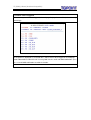
5.3.2 View of real-time monitored 8 D/I status on the web page
See picture below for the screen view of real-time monitored 8 D/I status the web page.
Therefore, user may view this summary thru his web-enable browser.
As it is displayed as such:
N: NORMAL (colored in blue)
A: ALARM (colored in red)
NC: NORMALLY CLOSED
NO: NORMALLY OPEN
DATA: the display of incoming RS232 data streams (if has)
ALARM_SUMMARY_C: automatically refresh this view display on the intervals of every
second.
Note:
1. The display contents; i.e, FIRE, GAS, DOOR OPEN, THIEF, of screen view can be
pre-edited. See **.** page for web view edition.
TP_ESM_8 Board (Arduino-Compatible)
5.3.3 When a D/I is triggered
Whenever any one of 8 D/I is triggered, the web page displays abnormalities (colored in red)
accordingly.
As the picture is displayed as such, both D/I 1 and D/I 2 have been triggered, the web page
shows abnormalities colored in red. User may both receive email and SMS notifications (if he
has set email/SMS notification to enabled selection.
TP_ESM_8 Board (Arduino-Compatible)
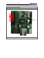
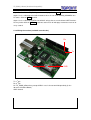
5.3.4 Wiring Connection (for D/I trigger)
TP_ESMS_8 Board offers 8 D/I for trigger. See the photo below for wiring connection
DI-1
DI-2
DI-4
DI-3
DI-5
DI-6
DI-7
DI-8
GND
(2nd/3rd pin)
TP_ESM_8 Board (Arduino-Compatible)
5.3.5 ASCII data as received from UART interface
TP_ESMS_8 Board is able to take in ASCII data as received from UART interface and display
them as such. The said ASCII data can be viewed on the real-time basis thru a web-enable
browser; however, the character strings of ASCII data should conform to the following
example.
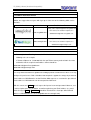
5.3.6 Standard format of ASCII data
The standard format should be like this: $RYCX=…\r
R means the location of horizontal Row that an ASCII string starts; it ranges from 1-8;
C means the location of vertical Column that an ASCII string starts, it ranges from 1-40;
… means the displayed contents on the monitor screen. Its maximum length should not
exceed 40 alphanumeric characters (Note: the limit depends on the location of R,C)
\r means the termination of a ASCII string
For example, if wanting to insert a character string of ASCII data at the location of Row 3,
Column 7, displaying 123 on the screen monitor, then the format and its corresponding
converted ASCII codes should be:
0D,24,52,33,43,37,3D,31,32,33,5C,72,0D
To simplify this format as possible,
If user usually inserts ASCII data at forefront Columns, which always means Column=0, and at
different horizontal Rows, which mean Row can be 1 or 2 or 3 or 4…..,etc Then he is able to
find out that
the acceptable variant of format can be: $RY=…
With this, user can compose some ASCII data, for example
0D,24,52,31,3D,31,32,33,34,35,36,0D to display an alphanumeric string 123456
0D,24,52,32,3D,36,37,38,39,31,32,0D to display 678912
0D,24,52,33,3D,32,33,34,35,36,37,38,39,0D to display 23456789
TP_ESM_8 Board (Arduino-Compatible)
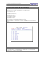
5.3.7 More examples of ASCII data
As said, there are 8 rows/ 40 columns to accommodate ASCII data. The example photo below
shows that grids have been covered fully.
5.3.8 Go to the web-page view of ASCII data
TP_ESM_8 Board (Arduino-Compatible)
Step1: Double-click on TP_ESMS_8 device as displayed under SetIP tag
Step2: User is redirected to the built-in browser where he can view ALARM_SUMMARY of 8
D/I status. Click on DATA hyperlink
Step3: User is redirected to DATA view of ASCII strings that are received from UART interface.
He may further click on DATA_C to activate auto refresh of web-page view on the intervals of
every second.
5.3.9 Wiring Connection (for ASCII transmission)
Rx
Tx
5V
GND
Tx: 1st pin
Rx: 2nd pin
5V: TP_ESMS_8 Board may accept 5VDC in case it has to work independently (in the
absence of Arduino Board )
GND: Ground
TP_ESM_8 Board (Arduino-Compatible)
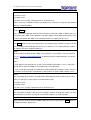
6 UPGRADE
TP_ESMS_8 accepts firmware upgrade via Ethernet LAN. See photos below for step-by-step
instruction.
Before firmware upgrade, user must have newest version of TP_ESMS_8.exe application
software ready. This application firmware is provided by TOPOINT CORP
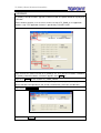
Step1: Execute the newest version of TP_ESMS_8.exe. User will have to locate a hardware
TP_ESMS_8 Board first before a firmware upgrade. Go to SetIP tag
Step2: Press Search to find available TP_ESMS_8 Board
Step3: After a few moments of search, TP_ESMS_8 Board (AR_145) is displayed at the
upmost row with corresponding IP and Version. A click on AR_145 to turn it to blue bar
Step4: Check Upgrade Enable
Step5: Switch to Upgrade tag
TP_ESM_8 Board (Arduino-Compatible)
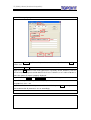
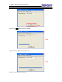
Step6: Press Start to launch firmware upgrade.
Step7
Step7: Firmware upgrade is being processed.
Step8
Step8: Firmware upgrade is finished.