1
ILL
ST
M
1
UP
CN
VE
/LI
OK
R
WE
PO
NG
IG
TR
Om
ron
ion
rat
DE
MA
2
WN CN
DO
rpo
Co
E
UT
EC
EX
E
OD
IN
N
PA
JA
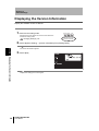
2D Code Reader
V400-F050/250/350
User’s Manual
Cat. No.
Z242-E1-04
Introduction
Thank you for purchasing the OMRON V400-F050/250/350.
This manual describes the functions, performance, and application
methods of the V400-F050/250/350.
This manual is intended for personnel with knowledge of electrical
systems. Be sure to read and understand this manual thoroughly before
using the product, and keep this manual in an easily accessible location
for quick reference when required.
Introduction
Section 1 Studying the V400-F
Section 2 Changing Reading Conditions
Section 3 Setting RS-232C and Discrete I/O Communication Conditions
Section 4 Other Settings
Section 5 Communicating with PC and Programmable Controller
Section 6 Troubleshooting
Appendix
2D Code Reader
User’s Manual
V400-F050/250/350
Introduction Section
ÇÕǹÇ?Ç
ëÊ 1 èÕ1 Section
ëÊ 2 èÕ2 Section
ëÊ 3 èÕ3 Section
ëÊ 4 èÕ4 Section 5 Section 6 Appendix
Introduction Application Considerations (Read and understand this information first.)
Introduction
Introduction
READ AND UNDERSTAND THIS DOCUMENT
Please read and understand this document before using the products. Please consult your OMRON
representative if you have any questions or comments.
WARRANTY
OMRON’s exclusive warranty is that the products are free from defects in materials and workmanship for
a period of one year (or other period if specified) from date of sale by OMRON.
OMRON MAKES NO WARRANTY OR REPRESENTATION, EXPRESS OR IMPLIED, REGARDING
NON-INFRINGEMENT, MERCHANTABILITY, OR FITNESS FOR PARTICULAR PURPOSE OF THE
PRODUCTS. ANY BUYER OR USER ACKNOWLEDGES THAT THE BUYER OR USER ALONE HAS
DETERMINED THAT THE PRODUCTS WILL SUITABLY MEET THE REQUIREMENTS OF THEIR
INTENDED USE. OMRON DISCLAIMS ALL OTHER WARRANTIES, EXPRESS OR IMPLIED.
LIMITATIONS OF LIABILITY
OMRON SHALL NOT BE RESPONSIBLE FOR SPECIAL, INDIRECT, OR CONSEQUENTIAL
DAMAGES, LOSS OF PROFITS OR COMMERCIAL LOSS IN ANY WAY CONNECTED WITH THE
PRODUCTS, WHETHER SUCH CLAIM IS BASED ON CONTRACT, WARRANTY, NEGLIGENCE, OR
STRICT LIABILITY.
In no event shall responsibility of OMRON for any act exceed the individual price of the product on which
liability is asserted.
IN NO EVENT SHALL OMRON BE RESPONSIBLE FOR WARRANTY, REPAIR, OR OTHER CLAIMS
REGARDING THE PRODUCTS UNLESS OMRON’S ANALYSIS CONFIRMS THAT THE PRODUCTS
WERE PROPERLY HANDLED, STORED, INSTALLED, AND MAINTAINED AND NOT SUBJECT TO
CONTAMINATION, ABUSE, MISUSE, OR INAPPROPRIATE MODIFICATION OR REPAIR.
SUITABILITY FOR USE
THE PRODUCTS CONTAINED IN THIS DOCUMENT ARE NOT SAFETY RATED. THEY ARE NOT
DESIGNED OR RATED FOR ENSURING SAFETY OF PERSONS, AND SHOULD NOT BE RELIED
UPON AS A SAFETY COMPONENT OR PROTECTIVE DEVICE FOR SUCH PURPOSES. Please refer
to separate catalogs for OMRON's safety rated products.
OMRON shall not be responsible for conformity with any standards, codes, or regulations that apply to
the combination of products in the customer’s application or use of the product.
At the customer’s request, OMRON will provide applicable third party certification documents identifying
ratings and limitations of use that apply to the products. This information by itself is not sufficient for a
complete determination of the suitability of the products in combination with the end product, machine,
system, or other application or use.
The following are some examples of applications for which particular attention must be given. This is not
intended to be an exhaustive list of all possible uses of the products, nor is it intended to imply that the
uses listed may be suitable for the products:
• Outdoor use, uses involving potential chemical contamination or electrical interference, or conditions or
uses not described in this document.
2
V400-F050/250/350
User’s Manual
Introduction
Introduction
• Nuclear energy control systems, combustion systems, railroad systems, aviation systems, medical
equipment, amusement machines, vehicles, safety equipment, and installations subject to separate
industry or government regulations.
• Systems, machines, and equipment that could present a risk to life or property.
Please know and observe all prohibitions of use applicable to the products.
NEVER USE THE PRODUCTS FOR AN APPLICATION INVOLVING SERIOUS RISK TO LIFE OR
PROPERTY WITHOUT ENSURING THAT THE SYSTEM AS A WHOLE HAS BEEN DESIGNED TO
ADDRESS THE RISKS, AND THAT THE OMRON PRODUCT IS PROPERLY RATED AND INSTALLED
FOR THE INTENDED USE WITHIN THE OVERALL EQUIPMENT OR SYSTEM.
PERFORMANCE DATA
Performance data given in this document is provided as a guide for the user in determining suitability and
does not constitute a warranty. It may represent the result of OMRON’s test conditions, and the users
must correlate it to actual application requirements. Actual performance is subject to the OMRON
Warranty and Limitations of Liability.
CHANGE IN SPECIFICATIONS
Product specifications and accessories may be changed at any time based on improvements and other
reasons.
It is our practice to change model numbers when published ratings or features are changed, or when
significant construction changes are made. However, some specifications of the product may be
changed without any notice. When in doubt, special model numbers may be assigned to fix or establish
key specifications for your application on your request. Please consult with your OMRON representative
at any time to confirm actual specifications of purchased products.
DIMENSIONS AND WEIGHTS
Dimensions and weights are nominal and are not to be used for manufacturing purposes, even when
tolerances are shown.
ERRORS AND OMISSIONS
The information in this document has been carefully checked and is believed to be accurate; however, no
responsibility is assumed for clerical, typographical, or proofreading errors, or omissions.
PROGRAMMABLE PRODUCTS
OMRON shall not be responsible for the user’s programming of a programmable product, or any
consequence thereof.
COPYRIGHT AND COPY PERMISSION
This document shall not be copied for sales or promotions without permission.
This document is protected by copyright and is intended solely for use in conjunction with the product.
Please notify us before copying or reproducing this document in any manner, for any other purpose. If
copying or transmitting this document to another, please copy or transmit it in its entirety.
V400-F050/250/350
User’s Manual
3
Introduction
Introduction
Meanings of Signal Words
In this manual, precautions are indicated using the following symbols and signal words to ensure safe
use of the V400-F050/250/350. The precautions indicated by these symbols and signal words
are important for safety and must be observed.
Indicates a potentially hazardous situation which, if not avoided, will
WARNING result in minor or moderate injury, or may result in serious injury or death.
Additionally there may be significant property damage.
Meanings of Alert Symbols
Indicates the possibility of explosion under specific conditions.
Indicates general prohibitions for which there is no specific symbol.
Alert Statements in this Manual
WARNING
This product is not designed or rated for ensuring safety of persons.
Do not use it for such purposes.
4
V400-F050/250/350
User’s Manual
Introduction
Introduction
Precautions for Safe Use
Observe the following precautions to ensure safe use of the product.
■ Installation Environment Precautions
• Do not use the product in environments with flammable or explosive gases.
• Do not install outdoors.
• Do not install the product close to high-voltage devices and power devices in order to
secure the safety of operation and maintenance.
• During installation, make sure that screws are tightened firmly.
■ Power Supply and Wiring Precautions
• Use the product with the power supply voltages specified in this manual.
• Use a DC power supply with countermeasures against high-voltage spikes (safe
extra low-voltage circuits on the secondary side).
p.20
■ Regulations and Standards
• EN61326-1
• Electromagnetic environment : Industrial electromagnetic environment (EN/IEC
61326-1 Table 2)
• The following condition is applied to the immunity test of this product.
a) If the level of disturbance of the video is such that characters on the monitor are
readable, the test is a pass.
b) Power line: 10 m max.
c) Signal line: 30 m max.
• Notice for Korea Radio Law
■ Other Precautions
• If the product becomes extremely hot, or abnormal odors or smoke occurs, stop using
the product immediately, turn OFF the power, and consult with your OMRON
representative.
• Dispose of the product as industrial waste.
• Do not apply pressure or deform the product when disposing of it.
V400-F050/250/350
User’s Manual
5
Introduction
Introduction
Precautions for Correct Use
Always observe the following precautions to prevent operation failures, malfunctions, and
adverse effects on performance and equipment.
■ Installation of the Product
Do not install the product in the following locations:
• Locations subject to ambient temperature that exceeds the rated temperature range
• Locations subject to rapid changes in temperature (causing condensation)
• Locations subject to relative humidity that exceeds the rated humidity range
• Locations subject to corrosive or flammable gases
• Locations subject to dust, salt, or metallic powder
• Locations subject to direct vibration or shock outside the specified ranges
• Locations subject to direct sunlight
• Locations subject to oil or chemical spray
Ambient Temperature
• Maintain a minimum clearance of 50 mm above and below the product to improve air
circulation.
• Do not install the product immediately above significant heat sources, such as
heaters, transformers, or large-capacity resistors.
• Do not let the ambient operating temperature exceed 45°C.
• Provide a forced-air fan cooling or air conditioning if the ambient temperature is near
45°C so that the ambient temperature never exceeds 45°C.
Noise Resistance
• Do not install the product in areas where highvoltage equipment is installed.
• Do not install the product within 200 mm of power
Power cable
200mm min.
cables.
200mm min.
POWER
OK
NG
Main unit
6
V400-F050/250/350
User’s Manual
Introduction
Introduction
■ Installation and Handling of Components
• Use the cables specified in this manual.
p.20
• Keep the power supply cable as short as possible (10 m maximum).
• The power lines and discrete I/O lines of the communication/power cable should not
be short-circuited with each other.
• Power output lines of the monitor cable should not be short-circuited with each other.
• Do not supply power from the monitor's power cable, since it is provided for output
only.
• Do not attempt to dismantle, repair, or modify the product. Failure to observe this may
result in breakdown or fire.
■ Connecting and Removing Cables
• Do not connect or disconnect the cables while power is supplied.
• Do not connect a cable to the 2D Code Reader if the other end of the cable is
connected to a personal computer or a Programmable Controller.
• To prevent damage from static electricity, use a wrist strap or another device for
preventing electrostatic charges when touching terminals or signal lines inside
connectors.
■ Turning OFF the Power Supply
• Do not turn OFF the power supply while a message is being displayed indicating that
processing is being performed. Data in memory will be destroyed, and the product
may not operate correctly the next time it is started.
• Do not turn OFF the power while the setting data is being saved. Data in memory will
be corrupted, and the product may not operate correctly the next time it is started.
V400-F050/250/350
User’s Manual
7
section_0a.fm Page 8 Tuesday, December 12, 2006 5:40 PM
Introduction
Page Format
Section title
Section 2
Changing Reading Conditions
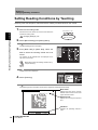
Setting Reading Conditions Manually
Outline
This section explains how to set reading conditions manually.
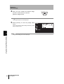
1. Switch to the setting mode.
STILL/LIVE MODE
Hold down the center button for more than two seconds to
activate the setting mode.
UP
TRIG
Section 2 Setting Reading Conditions Manually
Introduction How to Use This Manual
How to Use This Manual
EXECUTE DOWN
Hold down for more
than two seconds.
“Changing Settings” p.24
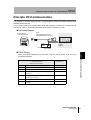
2. Select [Bank Setting] from [Setting Menu].
The [Bank Setting] screen will appear.
3. From
[Bank #00] to [Bank #09], select the
bank to which you want to set reading
condition.
The contents of the selected bank are displayed in the
right area of the screen.
The edit menu will be displayed.
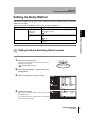
Index label
Provides the section number
and subject matter. Can be
used to immediately open the
desired page.
Screen display
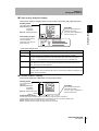
Setting item
Light Channel
Code Type
Shape
Settings
Details
Select the light to be used.
(For V400-F050)
Right CH.*
The light connected to the right light connector will be used.
Left CH.
The light connected to the left light connector will be used.
None
No light will be used.
Describes the settings.
Set the code type.
DataMatrix
The code will be read as a DataMatrix type code.
QRCode
The code will be read as a QRCode type code.
Auto*
The code type will be identified automatically.
Select the code shape.
This item is effective only when [DataMatrix] is selected for [Code Type].
Square
The code will be read as a square code.
Rectangle
The code will be read as a rectangular code.
Auto*
The code shape will be identified automatically.
V400-F050/250/350
User's Manual
31
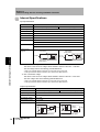
Procedure and additional explanations
Information useful during the operation and reference
pages are provided here with special marks to indicate
the kind of information being provided.
*This page does not actually exist in this manual.
8
V400-F050/250/350
User’s Manual
Introduction
Introduction Visual Aids
Visual Aids
Indicates points that are important in using product functions or in application procedures.
Indicates page numbers providing related information.
Indicates helpful information when a problem occurs and explanations of technical terms.
V400-F050/250/350
User’s Manual
9
Introduction
Introduction Contents
Contents
Introduction
Meanings of Signal Words
4
Meanings of Alert Symbols
4
Alert Statements in this Manual
4
Regulations and Standards
5
Precautions for Safe Use
5
Precautions for Correct Use
6
How to Use This Manual
8
Visual Aids
9
Contents
Section 1 Studying the V400-F
13
Features and Functions of V400-F
14
Installing and Connecting the Code Reader
18
Simple Teaching
22
Changing Settings
24
Reading Results
26
Section 2 Changing Reading Conditions
10
10
29
Setting Reading Conditions by Teaching
30
Setting Reading Conditions Manually
32
Selecting the Bank to be Used Normally
37
Copying a Bank
38
Deleting the Content of a Bank
40
Setting the Retry Method
41
V400-F050/250/350
User’s Manual
Introduction
43
Setting RS-232C Communication Conditions
44
Setting Discrete I/O Communication Conditions
48
Section 4 Other Settings
51
Setting Screen Display
52
Viewing the Images Read in the Past
53
Saving/Initializing All the Settings
56
Displaying the Version Information
58
Section 5 Communicating with PC and Programmable Controller
59
RS-232C Communication
60
Discrete I/O Communication
73
Section 6 Troubleshooting
81
Error Codes and Corrective Actions
82
Troubleshooting
82
Appendix
Introduction Contents
Section 3 Setting RS-232C and Discrete I/O Communication Conditions
85
Lens and Lighting
86
Line Speed and Reading Time/Exposure Time
91
Maintenance
93
Specifications and Dimensions
94
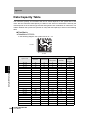
ASCII Table
99
Ladder Programming Example for Connecting to a PLC
100
FCS Check Program Example (BASIC)
104
Data Capacity Table
106
Menu Hierarchy
109
Revision History
110
V400-F050/250/350
User’s Manual
11
Introduction
Introduction Contents
12
MEMO
V400-F050/250/350
User’s Manual
This section provides items, such as the V400-F is features, installation,
connections and operation flow, with which the operator should be familiar to
use the V400-F.
Features and Functions of V400-F
14
Compact and Easy-to-Operate
14
Advanced Functions
16
Other Features
17
Installing and Connecting the Code Reader
Section 1 Studying the V400-F
Section 1
Studying the V400-F
18
Mounting the Main Unit
18
Connecting Peripheral Devices
20
Simple Teaching
22
Changing Settings
24
Reading Results
26
Monitor Display
26
RS-232C Communications Output
28
V400-F050/250/350
User’s Manual
13
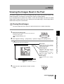
Section 1
Studying the V400-F
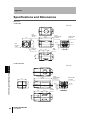
Features and Functions of V400-F
This fixed type 2D code reader provides advanced reading functions and is designed for easy
Section 1 Features and Functions of V400-F
operation by anyone. It reads 2D codes directly marked on boards and metal materials.
Two types of code reader are available: the V400-F250/350, whose lens and light are
integrated into one compact body, and the V400-F050, to which a C-mount lens can be
attached to enable use of various lights.
Compact and Easy-to-Operate
Light/Lens Integrated Type
V400-F250/350
Light and Lens are Integrated
Eliminates troublesome lens mounting and light.
V400-F250
V400-F350
Narrow-field light
Wide-field light
External size: 40
C-mount Type
× 50 × 97 mm
V400-F050
Allows Mounting of a C-mount Type Lens
Provides Two Connectors that
Allow Direct Connection of Light
No power source is required for the
light.
C-mount type lens
(Recommended:
p.89)
External size:
Supports
DataMatrix ECC200
(max. 64 × 64)
Readable codes
DataMatrix
• ECC200
10 × 10 to 64 × 64
8 × 18 to 16 × 48
14
V400-F050/250/350
User’s Manual
40 × 50 × 75 mm
Direct ring light
Low-angle ring light
(Recommended:
p.86)
QRCode
• Model 1, 2
21 × 21 to 57 × 57
(Version 1 to Version 10)
Back light
Reflected light
Coaxial light
Section 1
Studying the V400-F
Checking Reading Results by Easy-to-See LEDs
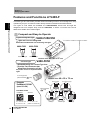
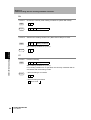
Easy Operations with 3 Buttons
OK LED (blue)
NG LED (red)
Lit when power is ON.
Lights up when reading is successful.
Lights up when
reading has failed.
Left button
Right button
Switches between still and realtime images. (* Monitor required)
Adjusts brightness (hold down for
two seconds). (* Monitor required)
POWER
OK
STILL/LIVE MODE
UP
Center button
TRIG
EXECUTE DOWN
Communication/power cable
connector
Monitor cable connector
CN2
CN1
u rc
e
----------Switches to setting mode
(hold down for two seconds).
Performs reading.
“Simple Teaching”
(Hold down for two seconds)
NG
er s
o
(* Monitor required)
MADE IN JAPAN
0)
p.20)
p .2
Programmable controller
To m o
nitor
(
(
To
hos
t de
vic
e/p
ow
Omron Corporation
One-Touch Reading by
“Simple Teaching” (
p.22)
Teaching/reading can be executed
and completed by just holding down
the right button for two seconds.
Reading can be started without
monitor.
Various Retry Functions
(
Power
supply
device
Section 1 Features and Functions of V400-F
POWER LED (green)
p.41)
Retry can be performed not only with
different exposure time, but also with
two or more reading conditions that
are switched automatically.
PC
Connecting to a Monitor
Allows Advanced Settings
POWER
SYNC
V400-F050/250/350
User’s Manual
15
Section 1
Studying the V400-F
Advanced Functions
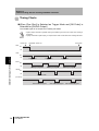
Retrying by switching to another bank automatically (
p.41)
Section 1 Features and Functions of V400-F
Retry is performed by switching the reading condition (Bank) among the
maximum five conditions.
Two condition switching methods are available: one which determines the order
of the conditions to be used automatically according to the frequency of their use,
and the other that switches them according to the registered order.
Combining with the retry settings that are made for each reading condition
enables various retry settings.
[Automatically determining the order according to frequency of use]
1st Bank
2nd Bank
Previous reading was successful.
Reading condition (example: 5th Bank)
3rd Bank
Successful retry count: 1
Successful retry count: 50
3rd Bank
1st Bank
Successful retry count: 50
Successful retry count: 25
4th Bank
4th Bank
Successful retry count: 15
Successful retry count: 15
5th Bank
2nd Bank
Successful retry count: 9
Successful retry count: 1
Successful retry count: 25
Setting the reading region (
For the 2nd and
subsequent
retries, the reading
condition used for
the 1st retry will be
excluded.
p.33)
Set the image region to be read.
This shortens the processing time.
Setting a filter (
p.34)
Performing
image
processing
before
reading reduces possibility of reading error.
Filtering can be performed in 3 steps.
• Smooth, Dilate/Erosion, Median
16
V400-F050/250/350
User’s Manual
Section 1
Studying the V400-F
Enables switching between two lights (V400-F050 only) (
p.34)
The light to be used can be switched
between two lights according to the
Combining this function with the auto
bank switch retry function enables the
code
reader
to
handle
partially
reflecting work pieces.
Other Features
Saves up to 10 reading conditions (
Saves up to 28 past read images (
p.30)
p.53)
This allows you to identify the errors that occurred, by checking the saved past images.
Supports NPN/PNP by simply exchanging the cable.
Allows direct power supply to the monitor.
Section 1 Features and Functions of V400-F
situation.
Use of the monitor cable (V400-WM0) and LCD monitor (F150-M05L-2D) enables the
V400-F to supply power to the monitor, making settings monitoring and maintenance
easy.
Displays results in various ways (
p.26)
Displays analysis result of code quality numerically
and graphically (bar).
Code quality analysis display (
p.27)
Highlights the reading state.
Highlighting (
p.26)
Displays the RS-232C communication history.
Communication history display (
p.27)
V400-F050/250/350
User’s Manual
17
Section 1
Studying the V400-F
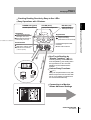
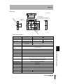
Installing and Connecting the Code Reader
.
Mount the reader at a distance where the code image can be shot correctly.
There are two mounting methods: “DIN track mounting” and “Base mounting”.
Field of Vision and Distance from the Code
• An accurate image will not be obtained if the installation distance is too long or too short. Always use
the installation distance given below.
• The field of vision and installation distance of the V400-F050 vary with the lens to be used.
“Selecting a Lens” p.89
V400-F350
orpo
C
ron
1
UP
IVE
OK
ST
/L
ILL
CN
NG
MO
E
DE
C
XE
Om
UT
TR
E
IG
DO
ratio
n
MA
WN CN
2
DE
IN
JA
PA
N
V400-F250
R
WE
PO
Section 1 Installing and Connecting the Code Reader
Mounting the Main Unit
Installation distance:
200 mm
Installation distance:
100 mm
Code
Code
Field of vision
14 × 18.5 mm
Field of vision
31 × 42 mm
Glossy Workpieces
Install the Main Unit at an angle so that regular reflective light is not included in the
image.
Recommended Installation Angle
Model
Recommended angle
V400-F250 10°
V400-F350 5°
18
V400-F050/250/350
User’s Manual
Section 1
Studying the V400-F
Base Mounting
Mount the reader with four M3 screws.
Mounting dimensions
(Unit: mm)
Mounting the Mount Seat
First mount the mount seat, then mount the reader to the seat with two M4 screws. The
reader can also be mounted with one 1/4-20UNC screw.
Mounting dimensions
(Unit: mm)
2-M4
(Screw fitting length: 8 mm or less)
Section 1 Installing and Connecting the Code Reader
2-M3
(Screw fitting length: 5 mm or less)
1/4-20 UNC
(Screw fitting length: 8 mm or less)
DIN Track Mounting
1. Mount
the mount seat to the
2. Slide the seat into the DIN rail, and
undersurface of the base of the
then tighten the two screws at one
reader with M3 screws (supplied
edge of the rail using the hexagonal
with the reader).
wrench (supplied with the reader).
V400-F050/250/350
User’s Manual
19
Section 1
Studying the V400-F
Connecting Peripheral Devices
Connect peripheral devices to the reader.
Section 1 Installing and Connecting the Code Reader
Always turn OFF the reader before connecting or disconnecting a peripheral device's cable.
Peripheral devices may be damaged if the cable is connected or disconnected with the power ON.
The connector (CN2) for the monitor is capped when the reader is shipped. The cap must be left on
those connectors that are not used to protect them from dust, dirt and static electricity.
Main
Monitor
F150-M05L-2D
Align the
marks.
Align the
marks.
When plugging in a
connector, push it with a
force of no more than
15 to 20 N.
Then, pull gently on the
cable (approximately
10 N) to make sure the
connector is securely
connected.
Attach a ferrite core.
The ferrite core must
be located at least
10 mm away from the
base of the connector.
Monitor cable
Communication/ V400-W23 (NPN type)
power cable V400-W23P (PNP type)
PC
V400-W24 (NPN type)
V400-W24P (PNP type)
Communication/
power cable
Brown
Blue
Power
supply
device
V400-WM0
or
Programmable controller
+24 V
Brown
Blue
Brown
Recommended: OMRON
S8VS-03024
Recommended: OMRON
S8VS-03024
Power
supply
device
Programmable controller
PC
Discrete I/O
Wiring method: p.73
Make sure that the
connector is oriented
correctly and not inserted
at an angle. Secure the
connector using the
screws on both sides of
the connector.
20
V400-F050/250/350
User’s Manual
RS-232C connector
(male)
RS-232C connector
RS-232C connector
(female)
RS-232C connector
Make sure that the
connector is oriented
correctly and not inserted
at an angle. Secure the
connector using the
screws on both sides of
the connector.
0V
Blue
Section 1
Studying the V400-F
Lens and light (for V400-F050 only)
Right-side light cable connector
To the light
Align the projection on the light
cable is connector with the slot on
the connector of the reader.
C-mount type lens
Recommended lens: p.89
Recommended light: p.86
Light
Light cable
To the light
Power
For V400-F050/250/350, a power supply device must be provided separately.
Wire the power supply independently of other devices. In particular, keep the
power supply wired separately from inductive loads.
Use a DC power supply with safety measures against high-voltage spikes (safety extra lowvoltage circuits on the secondary side). If UL recognition is required for the overall system, use
a UL Class II DC power supply.
Use a power supply that meets the following requirements.
Output current
1.2 A min.
Power supply voltage
24 VDC ±10%
Recommended
S8VS-03024
Section 1 Installing and Connecting the Code Reader
Left-side light cable connector
Connect the brown wire to the positive (+) side of the power
supply and the blue wire to the negative (-) side.
(+) side Brown
(-) side Blue
Handling the Cable
After the connector is plugged in, do not apply a
force of more than 30 N to the connector in the
directions shown below.
Excessive force will damage the connector.
When disconnecting a cable, hold the part of the
plug shown below and then pull it out straight.
Hold this part.
30 N max.
30 N max.
30 N max.
V400-F050/250/350
User’s Manual
21
Section 1
Studying the V400-F
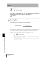
Simple Teaching
Use “Simple Teaching” to check whether codes on the work piece are readable.
Section 1 Simple Teaching
“Simple Teaching” enables you to set necessary reading conditions automatically by simple
operations.
To change reading conditions or set them in detail, use the setting mode.
Turning ON the power
Turn ON the power to the monitor.
• When using F150-M05L-2D, make sure
that it is connected before turning ON the
power to the power supply device.
The POWER LED
(green) will light up.
Turn ON the power to the power supply device.
The POWER LED (green) will light up.
Performing teaching
Capture the work piece.
Switch to the real-time image display
mode, and adjust the position and
brightness of the work piece while
observing the image on the monitor.
[STILL]: Still image
[LIVE]: Real-time image
Display switching
Press the left button to switch
from the still image to the realtime image or vice versa.
Press
Brightness adjustment
Hold down the left button for more
than two seconds, to display the
exposure time adjustment screen.
The brightness will be adjusted
based on the exposure time.
Perform teaching.
Hold down for
more than two
seconds.
Hold down the right button for
more than two seconds, to perform
“Simple Teaching”.
When teaching is completed successfully, the
teaching and reading results will be displayed.
Three indicators will light: Power (green), OK
(blue), and NG (red). Select [OK] to save the
results.
Indicators light:
Power (green), OK (blue),
NG (red).
22
V400-F050/250/350
User’s Manual
Hold down for
more than two
seconds.
Section 1
Studying the V400-F
Exiting
Turn OFF the power to the power supply device and then to the monitor.
V400-F050/250/350
User’s Manual
Section 1 Simple Teaching
• The teaching results will be overwritten, registered to [Bank #00], and saved.
• If [Cancel] is selected in the result display screen, the results will not be saved.
23
Section 1
Studying the V400-F
Changing Settings
The setting mode allows you to make changes to reading conditions and system settings. This
Section 1 Changing Settings
section explains operations for the setting mode.
Switch to the setting mode.
Hold down the center button for more than two seconds.
All the LEDs will light up and the [Setting Menu] appears.
Hold down for more
than two seconds.
All LEDs light up.
Make settings
Basic operation for setting mode
Use the right and left buttons to select the desired item, and
then press the center button to confirm the selection.
Name of currently
selected menu
Selectable menus are
enclosed in a white frame.
To close the current menu, select [Exit] and then press the
center button.
Select an item.
Confirm
Select an item.
Select [Exit] to
close the menu.
(Example) When [Bank Setting] is selected
Indicates that this reading condition is
normally used.
* Only when [Bank Setting] is selected
Numerical value inputting method
Move the cursor to the desired item
and press the center button.
Change the value using the right and
left buttons.
Press the center button to confirm the
setting.
24
V400-F050/250/350
User’s Manual
The currently
selected item is
enclosed in a
blue frame.
(Cursor)
Section 1
Studying the V400-F
p.29
Select [Bank Setting] from [Setting Menu].
• Up to 10 reading conditions are available.
• When a reading condition is selected, its
settings will be displayed in the right area of the
screen.
• Select the desired reading condition from
among the ten conditions, and set each
condition item manually or by teaching.
• Reading conditions can be copied or deleted.
Section 1 Changing Settings
Setting the reading conditions
Reading condition [Bank #00]
contains the contents of
“Simple Teaching”.
Other settings
Select [System Setting] from [Setting Menu].
[RS-232C]
Set RS-232C communication related parameters such as
baud rate and parity.
p.44
[Data Format]
Set data format setting for RS-232C communication.
p.46
[Discrete I/O]
Set discrete I/O related settings including trigger mode
and busy input.
p.48
[Display]
Change the monitor display method.
p.52
[Image Store]
Select the methods for storing images and referring to
stored images.
p.53
[Bank Switching]
Change the automatic bank switch retry setting.
p.41
[Version Information] Displays the software version.
Saving the settings
p.58
p.56
Select [Save] from [Setting Menu].
All the settings including reading conditions will be saved.
Before exiting, make sure to save
the settings in the setting mode.
If the settings are not saved, the
reading conditions and other
settings will be lost.
V400-F050/250/350
User’s Manual
25
Section 1
Studying the V400-F
Reading Results
This section explains details of the read results.
Section 1 Reading Results
Monitor Display
Explanation of reading results displayed on the monitor is given below.
There are four display methods: normal display, highlighting display, code quality
analysis display and communication display.
The desired display method can be set in the setting mode.
Display setting: p.52
Normal Display
Normal screen
Reading status
The reading status is
displayed.
OK (blue):Reading is
completed
successfully.
NG (red): Reading has
failed.
Read data
The read data is displayed.
(Max. 208 characters =
8 lines × 26 characters)
An error code is displayed in case of
reading error.
• Error code contents
Error code
Action
?E000
2D code cannot be found, possibly due to uneven background. Check the work piece
surface and lighting condition.
?E100
2D code cell cannot be recognized correctly. Check the marking and lighting conditions,
and then perform teaching again.
?E200
Reading was not completed within the specified period of time. Check the work piece and
lighting condition, then perform teaching again.
Increase the reading timeout value.
If reading has failed, it may be possible that the cause can be identified by checking the read image.
p.53
Highlighting Display
The screen is enclosed in a frame whose color that indicates the reading status.
Reading status
The reading status is
displayed.
OK (blue):Reading is
completed
successfully.
NG (red): Reading has failed.
26
V400-F050/250/350
User’s Manual
Read data
The read data is displayed.
(Max. 26 characters)
An error code is displayed in
case of reading error.
Section 1
Studying the V400-F
Code quality analysis display
This screen displays analysis result of code quality numerically and graphically (bar).
The reading status is displayed.
OK (blue):Reading is
completed
successfully.
NG (red): Reading has failed.
Read data
The read data is displayed.
(Max. 26 characters)
An error code is displayed in
case of reading error.
Code quality analysis
The code quality analysis
result is displayed
numerically (0 to 100) and
graphically (bar).
Section 1 Reading Results
Reading status
• Code quality analysis items
Item
Description
Reading Rate
Displays the rate of successful reading count to the total reading count.
Contrast
Evaluates the code is white/black contrast that varies with the lighting condition.
The larger the difference between the white and black parts of the code, the larger the
contrast. “1” will be displayed if the code is contrast is the minimum readable level.
Focus
Evaluates the focus level of the image.
If the code is out of focus, it can no longer be recognized. The more the code is out of
focus, the smaller the value displayed.
Cell
Evaluates the number of recognition fails for each cell in the finder pattern, timing pattern
and data.
The more cells in which recognition failure occurs and the more unstable the reading is, the
smaller the value displayed.
Communication Display
This screen displays the RS-232C communication history.
Reading status
The reading status is
displayed.
OK (blue):Reading is
completed
successfully.
NG (red): Reading has failed.
Read data
The read data is displayed.
(Max. 26 characters)
An error code is displayed in
case of reading error.
Communication history
The RS-232C communication history is indicated by yellow and green characters.
Communication contents are displayed from the bottom to the top of the history display area.
Yellow: Indicates that the content was input to the main body.
Green: Indicates that the content was output from the main body.
V400-F050/250/350
User’s Manual
27
Section 1
Studying the V400-F
RS-232C Communications Output
Section 1 Reading Results
This section explains the reading results to be output via RS-232C communication.
When reading is successful
The read data is output in the following format.
Number of read data digits Code quality
Read data
“Number of read data digits” and “Code quality” are output only if [Digit Data] and
[Checker Data] are set to [ON] in the data format setting.
p.46
When reading has failed
By factory default, an error code is output in the following format. However, it is
possible to make a data format setting so that no error code will be output.
Error code output setting: p.47
Header
?E000
Footer
Error code: p.26, p.82
28
V400-F050/250/350
User’s Manual
Section 2
Changing Reading Conditions
Setting Reading Conditions by Teaching
30
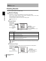
Setting Reading Conditions Manually
32
Selecting the Bank to be Used Normally
37
Copying a Bank
38
Deleting the Content of a Bank
40
Setting the Retry Method
41
Setting the Bank Switching Retry Function
Section 2 Changing Reading Conditions
This section provides information required for changing reading conditions.
41
V400-F050/250/350
User’s Manual
29
Section 2
Changing Reading Conditions
Setting Reading Conditions by Teaching
Teaching uses one sample to read it and sets a reading condition based on the results.
1. Switch to the setting mode.
STILL/LIVE MODE
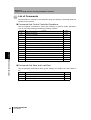
TRIG
Section 2 Setting Reading Conditions by Teaching
Hold down the center button for more than two seconds to
activate the setting mode.
“Changing Settings” p.24
UP
EXECUTE DOWN
Hold down for more
than two seconds.
2. Select [Bank Setting] from [Setting Menu].
The [Bank Setting] screen will appear.
3. From
[Bank #00] to [Bank #09], select the
bank to which the teaching results are to be
saved.
The contents of the selected bank are displayed in the
right area of the screen.
[Bank #00] contains the reading condition set by
“Simple Teaching”.
The edit menu will be displayed.
4. Select [Teaching].
The [Teaching] screen will appear and the screen brightness is adjusted automatically.
Menu name
Displays the name of the currently
selected menu and the name of the
upper hierarchical level.
Exposure time
Displays the currently set exposure
time.
Guidance
Displays the operating method in
brief.
30
V400-F050/250/350
User’s Manual
Section 2
Changing Reading Conditions
5. Adjust the brightness.
Check the automatically adjusted brightness.
To change the brightness, press the right and left buttons.
The brightness is adjusted based on the exposure
time. The longer the exposure time, the brighter
the image but the image is easily blurred if the work
piece is not stationary.
STILL/LIVE MODE
UP
TRIG
EXECUTE DOWN
Press
p.91
Press the center button.
STILL/LIVE MODE
UP
Section 2 Setting Reading Conditions by Teaching
6. Confirm the brightness.
TRIG
EXECUTE DOWN
Press
Teaching will start.
When teaching is complete, the teaching results are
displayed.
7. Checking the results.
Check the teaching results.
To change the reading condition, select the condition item
to be changed. For details, refer to “Setting Reading
Conditions Manually” p.32.
8. Confirm the reading condition.
Select [OK] to confirm the reading condition. This will
bring you to the operation menu.
If you select [Cancel], the operation menu will reappear
without reflecting the teaching results.
9. Save the settings.
Select [Save] from [Setting Menu] to save the changes
you have made to the reading condition.
p.56
V400-F050/250/350
User’s Manual
31
Section 2
Changing Reading Conditions
Setting Reading Conditions Manually
This section explains how to set reading conditions manually.
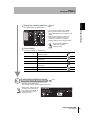
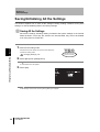
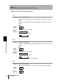
1. Switch to the setting mode.
Section 2 Setting Reading Conditions Manually
Hold down the center button for more than two seconds to
activate the setting mode.
“Changing Settings” p.24
2. Select [Bank Setting] from [Setting Menu].
The [Bank Setting] screen will appear.
3. From
[Bank #00] to [Bank #09], select the
bank to which you want to set reading
condition.
The contents of the selected bank are displayed in the
right area of the screen.
The edit menu will be displayed.
4. Select [Edit].
The reading condition change menu will appear.
5. Make changes to the reading condition.
For reading condition items, refer to “Reading Condition
Items” (
p.33).
6. Confirm the reading condition.
Select [OK] to confirm the reading condition. This will
bring you to the operation menu.
If you select [Cancel], the operation menu will reappear
without reflecting the changes.
32
V400-F050/250/350
User’s Manual
STILL/LIVE MODE
UP
TRIG
EXECUTE DOWN
Hold down for more
than two seconds.
Section 2
Changing Reading Conditions
7. Save the settings.
Select [Save] from [Setting Menu] to save the changes you have made to the reading condition.
p.56
Reading Condition Items
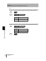
[Exposure Time]
Set the desired exposure time. The longer the exposure time, the brighter the image is, but the image is
blurred easily if the work piece is not stationary.
p.91
The brightness changes in real time
as you change the setting.
Set the desired exposure time.
0.03 to 10.00 (msec)
Select [OK] to confirm the changes
and return to the edit menu.
Select [Cancel] to cancel the
changes and return to the edit menu.
[Search Region]
Set the image region to be read. The region enclosed by the red and green boundary lines will be the subject
Section 2 Setting Reading Conditions Manually
of reading.
Start Y
Start X
The region boundary lines move in
real time as you change the setting.
Line type
Terminal X
Terminal Y
Set the region boundary lines.
Select [OK] to confirm the changes and return to the
edit menu.
Select [Cancel] to cancel the changes and return to
the edit menu.
Red:
Currently
changed region
boundary line
Green: Region
boundary line
Black: Boundary line
outside region
In the actual screen, the
same line type and
thickness are used.
Different type and
thickness are used to
make color distinction
easier.
V400-F050/250/350
User’s Manual
33
Section 2
Changing Reading Conditions
[Filter]
Set the image processing to be performed at completion of reading. This will lower the possibility of reading
failure.
Filtering can be performed in 3 steps (filter type can be selected from Smooth, Dilate, Erosion and Median).
Section 2 Setting Reading Conditions Manually
The image changes in real time as
you change the setting.
Filter
Select [OK] to confirm the changes
and return to the edit menu.
Select [Cancel] to cancel the
changes and return to the edit menu.
Settings
Details
Smooth 3 × 3
Smoothing filter. This filter smooths the image.
The filter size can be selected from 3 × 3 and 5 × 5.
Smooth 5 × 5
Dilate 3 × 3
Dilate filter. This filter makes the cell smaller if the code is black.
The filter size can be selected from 3 × 3 and 5 × 5.
Dilate 5 × 5
Erosion 3 × 3
Erosion filter. This filter makes the cell larger if the code is black.
The filter size can be selected from 3 × 3 and 5 × 5.
Erosion 5 × 5
Median 3 × 3
Median 5 × 5
Median filter. This filter eliminates noise.
The filter size can be selected from 3 × 3 and 5 × 5.
None*
No filtering is performed.
The default settings are indicated with an asterisk (*).
Other Settings
Setting item
Light Channel
(For V400-F050)
34
Settings
Details
Select the light to be used.
Left CH.*
The light connected to the left light connector will be used.
Right CH.
The light connected to the right light connector will be used.
None
No light will be used.
Lighting
(For V400-F250/
350)
ON*
The light will be used.
OFF
The light will not be used.
Code Type
Set the code type.
V400-F050/250/350
User’s Manual
DataMatrix
The code will be read as a DataMatrix type code.
QRCode
The code will be read as a QRCode type code.
Auto*
The code type will be identified automatically.
Section 2
Changing Reading Conditions
Setting item
Shape
Settings
Select the code shape.
This item is effective only when [DataMatrix] is selected for [Code Type].
Square
Model
Size
The code will be read as a square code.
Rectangle
The code will be read as a rectangular code.
Auto*
The code shape will be identified automatically.
Select the QR code model.
This item can be selected only when [QRCode] is selected for [Code Type].
Model 1
The code will be handled as Model 1 code.
Model 2
The code will be handled as Model 2 code.
Auto*
The code model will be identified automatically.
Select the error correction level (ECC level).
200
The code will be read as the ECC level recommended by ECC200
(AIM).
Only this item is available if [DataMatrix] is selected for [Code
Type].
L (7%)*
Up to 7% damage can be handled.
This item can be selected only when [QRCode] is selected for
[Code Type].
M (15%)
Up to 15% damage can be handled.
This item can be selected only when [QRCode] is selected for
[Code Type].
Q (25%)
Up to 25% damage can be handled.
This item can be selected only when [QRCode] is selected for
[Code Type].
H (30%)
Up to 30% damage can be handled.
This item can be selected only when [QRCode] is selected for
[Code Type].
Auto*
The ECC level will be identified automatically.
Section 2 Setting Reading Conditions Manually
Ecc Level
Details
Select the number of cells present for each side of the code. The size varies with the
code.
10 × 10 to 64 × 64 This item can be selected only when [Square] is selected for
[Shape].
8 × 18 to 16 × 48
This item can be selected only when [Rectangle] is selected for
[Shape].
21 × 21 to 57 × 57 This item can be selected only when [QRCode] is selected for
[Code Type].
Auto*
Length
Mirror
The size will be identified automatically.
Enter the code length (the length on the screen) in pixels.
50 to 480
-
Auto*
The length will be identified automatically.
Select the mirror image.
Normal
The code will be read as a non-reverse image (in normal direction).
Reverse
The code will be read as a mirrored image (in reverse direction).
Auto*
Whether the code is a normal or reverse image will be identified
automatically.
V400-F050/250/350
User’s Manual
35
Section 2
Changing Reading Conditions
Setting item
Color
Timeout
Settings
Set the code cell color.
Black
The code will be read as a black code.
White
The code will be read as a white code.
Auto*
The color will be identified automatically.
Enter the time (in msec) allowed before reading is completed after it is started.
Section 2 Setting Reading Conditions Manually
100 to 9999
(2000*)
Retry
Details
-
Set this item when you need to retry (capture the image twice or more) after reading is
executed. Capturing the image can be performed with a different exposure time.
It is possible to retry capturing the image twice or more with different reading
conditions.
“Setting the Bank Switching Retry Function” p.41
None*
Capture will not be retried (i.e. capture will be performed only
once).
Exposure
Allows retry with different exposure time. Capturing the image can
be performed twice or more with a different exposure time.
For instance, if [02.00 msec] is set for [Step], [2 times] for
[Increment] and [2 times] for [Decrement], the exposure time will
be changed each time capture is performed, starting from 10 msec
to 12 msec, 8 msec, 14 msec and then 6 msec (if the original
exposure time is 10 msec).
Normal
Simple retry. Capture will be retried with the same reading
condition.
Step
0.01 to 05.00*
(0.30*)
Set the step (msec) in which the exposure time is changed.
This item can be selected only when [Exposure] is selected for
[Retry].
Increment
0 to 4 (2*)
Set the number of times (Times) the exposure time is to be
increased.
This item can be selected only when [Exposure] is selected for
[Retry].
Decrement
0 to 4 (2*)
Set the number of times (Times) the exposure time is to be
decreased.
This item can be selected only when [Exposure] is selected for
[Retry].
Interval
32 to 999 (100*)
Set the interval (msec) at which capture is to be performed.
This item can be selected only when [Normal] is selected for
[Retry].
Max Count
0 to 8 (4*)
Set the number of times (Times) capture is to be repeated.
This item can be selected only when [Normal] is selected for
[Retry].
The default settings are indicated with an asterisk (*). However, in the case of [Bank #00], [Exposure] will be
set for [Retry] as the default.
36
V400-F050/250/350
User’s Manual
Section 2
Changing Reading Conditions
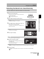
Selecting the Bank to be Used Normally
This section explains how to select the bank that is to be used normally.
1. Switch to the setting mode.
STILL/LIVE MODE
TRIG
activate the setting mode.
“Changing Settings” p.24
UP
Section 2 Selecting the Bank to be Used Normally
Hold down the center button for more than two seconds to
EXECUTE DOWN
Hold down for more
than two seconds.
2. Select [Bank Setting] from [Setting Menu].
The [Bank Setting] screen will appear.
3. From
[Bank #00] to [Bank #09], select the
bank that is to be used normally.
The contents of the selected bank are displayed in the
right area of the screen.
The edit menu will be displayed.
4. Select [Set Use Bank].
A confirmation message will be displayed.
5. Confirm the reading condition.
Select [OK] to confirm the setting. This will bring you to
the operation menu.
If you select [Cancel], the operation menu will reappear
without reflecting the changes.
An asterisk (*) will appear at both right and left ends of the reading condition to be normally used.
6. Save the settings.
Select [Save] from [Setting Menu] to save the changes you have made to the reading condition.
p.56
V400-F050/250/350
User’s Manual
37
Section 2
Changing Reading Conditions
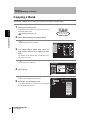
Copying a Bank
This section explains how to copy the content of one bank to another bank.
1. Switch to the setting mode.
Section 2 Copying a Bank
Hold down the center button for more than two seconds to
activate the setting mode.
“Changing Settings” p.24
2. Select [Bank Setting] from [Setting Menu].
The [Bank Setting] screen will appear.
3. From
[Bank #00] to [Bank #09], select the
bank whose content is to be copied to another
bank.
The contents of the selected bank are displayed in the
right area of the screen.
The edit menu will be displayed.
4. Select [Copy].
A confirmation message will be displayed.
5. Select the copy destination bank.
If you select [Cancel], the operation menu will reappear
without reflecting the changes.
38
V400-F050/250/350
User’s Manual
STILL/LIVE MODE
UP
TRIG
EXECUTE DOWN
Hold down for more
than two seconds.
Section 2
Changing Reading Conditions
A confirmation message will be displayed.
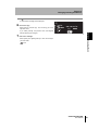
6. Execute copy.
Select [OK] to execute copy. This will bring you to the
operation menu.
If you select [Cancel], the previous menu will reappear
Section 2 Copying a Bank
without reflecting the changes.
7. Save the settings.
Select [Save] from [Setting Menu] to save the changes
you have made.
p.56
V400-F050/250/350
User’s Manual
39
Section 2
Changing Reading Conditions
Deleting the Content of a Bank
This section explains how to delete the content of a bank and restore the default settings for
that bank.
Section 2 Deleting the Content of a Bank
1. Switch to the setting mode.
Hold down the center button for more than two seconds to
activate the setting mode.
“Changing Settings” p.24
STILL/LIVE MODE
UP
TRIG
EXECUTE DOWN
Hold down for more
than two seconds.
2. Select [Bank Setting] from [Setting Menu].
The [Bank Setting] screen will appear.
3. From
[Bank #00] to [Bank #09], select the
bank whose content is to be deleted.
The contents of the selected bank are displayed in the
right area of the screen.
The edit menu will be displayed.
4. Select [Delete].
A confirmation message will be displayed.
5. Execute deletion.
Select [OK] to confirm the settings. This will bring you to
the operation menu.
If you select [Cancel], the operation menu will reappear
without deletion.
The content of the selected bank will be deleted, and the default settings will be restored for that bank.
6. Save the settings.
Select [Save] from [Setting Menu] to save the settings.
p.56
40
V400-F050/250/350
User’s Manual
Section 2
Changing Reading Conditions
Setting the Retry Method
This section explains how to set the retry method (to execute reading and then capture an
image twice or more).
Two retry methods are available: “Same bank” and “Bank Switching”.
Item
Details
Exposure time
change retry
(Exposure)
Capture is performed for the same bank by changing the
exposure time in steps.
p.36
Simple retry (Normal) Capture is performed the specified number of times for the same
bank.
p.36
Automatic bank switch retry (Bank Switching)
Capture is performed continuously by switching from one bank
to another.
Setting the Bank Switching Retry Function
1. Switch to the setting mode.
Hold down the center button for more than two seconds to
activate the setting mode.
“Changing Settings” p.24
STILL/LIVE MODE
UP
Section 2 Setting the Retry Method
Same bank
TRIG
EXECUTE DOWN
Hold down for more
than two seconds.
2. Select [System Setting] [Bank Switch] from
[Setting Menu].
3. Make the desired bank switch settings.
4. Confirm the settings.
Select [OK] to confirm the settings. This will bring you to
the operation menu.
If you select [Cancel], the operation menu will reappear
without reflecting the settings.
V400-F050/250/350
User’s Manual
41
Section 2
Changing Reading Conditions
5. Save the settings.
Select [Save] from [Setting Menu] to save the settings.
p.56
Setting item
Switch Function
Section 2 Setting the Retry Method
42
1st Bank
2nd Bank
3rd Bank
4th Bank
5th Bank
Settings
Details
OFF*/ON
If [ON] is selected, the bank will be switched from one to
another as specified.
1st Bank:
#00 to #09 (*#00)
Other:
#00 to #09, None*
Select the reading conditions to be switched.
No reading condition will be selected if [None] is selected.
Total Timeout
1000 to 9999 (9999*) Set the time at which reading is to be stopped following start of
bank switch retry in case of reading failure.
Switch Order
Select the reading condition switching method.
V400-F050/250/350
User’s Manual
Auto*
The switching order is determined automatically based on the
frequency of use.
Fixed
Banks will be switched in the order they have been registered,
starting from [1st Bank].
Section 3
Setting RS-232C and Discrete I/O
Communication Conditions
This section explains how to set RS-232C and discrete I/O communication
Setting RS-232C Communication Conditions
44
Setting Communication Conditions
44
Setting the Data Format
46
Setting Discrete I/O Communication Conditions
48
V400-F050/250/350
User’s Manual
Section 3 Setting RS-232C and Discrete I/O Communication Conditions
conditions.
43
Section 3
Setting RS-232C and Discrete I/O Communication Conditions
Setting RS-232C Communication Conditions
This section explains how to set RS-232C communication conditions and data format.
Setting Communication Conditions
Set RS-232C communication conditions as follows.
Section 3 Setting RS-232C Communication Conditions
1. Switch to the setting mode.
Hold down the center button for more than two seconds to
activate the setting mode.
“Changing Settings” p.24
2. Select [System Setting] [RS-232C] from [Setting Menu].
The RS-232C setting menu will appear.
3. Make the desired changes to the settings.
4. Confirm the changes.
Select [OK] to confirm the changes made to the [RS232C] settings. This will bring you to the operation menu.
If you select [Cancel], the operation menu will reappear
without reflecting the changes.
5. Save the settings.
Select [Save] from [Setting Menu] to save the settings.
p.56
44
V400-F050/250/350
User’s Manual
STILL/LIVE MODE
UP
TRIG
EXECUTE DOWN
Hold down for more
than two seconds.
Section 3
Setting RS-232C and Discrete I/O Communication Conditions
Setting item
Baud Rate
Parity
Settings
Details
9600*/19200/38400/
57600/115200
Select the desired baud rate (bps).
Baud rates exceeding 20 kbps are not defined in the RS232C standards. Therefore, if [38400 bps] or higher
baud rate is selected, communications may be
unreliable depending on the cable length.
If there are problems with communications, a baud rate
of [19200 bps] or below must be used.
Select the desired parity. Parity is used to detect data failure.
No parity will be used.
Odd
Odd parity will be used.
Even
Even parity will be used.
Data Length
8*/7
Select the data length to be used.
The data length is the number of bits required to send one
character.
Stop Bit
1*/2
Select the stop bit length to be used.
The stop bit indicates the end of data.
The default settings are indicated with an asterisk (*).
Make the communication settings as follows when using save or load command (e.g. CB, CU).
Parity: None, Data Length: 8, Stop Bit: 1
p.71
V400-F050/250/350
User’s Manual
Section 3 Setting RS-232C Communication Conditions
None*
45
Section 3
Setting RS-232C and Discrete I/O Communication Conditions
Setting the Data Format
Set the RS-232Cdata format as follows.
1. Switch to the setting mode.
STILL/LIVE MODE
Hold down the center button for more than two seconds to
activate the setting mode.
“Changing Settings” p.24
Section 3 Setting RS-232C Communication Conditions
The [Data Format] setting menu will appear.
3. Make the desired changes to the settings.
“Description of Format” p.63
4. Confirm the changes.
Select [OK] to confirm the changes made to the [Data
Format] settings. This will bring you to the operation
menu.
If you select [Cancel], the operation menu will reappear
5. Save the settings.
Select [Save] from [Setting Menu] to save the settings.
p.56
V400-F050/250/350
User’s Manual
TRIG
EXECUTE DOWN
Hold down for more
than two seconds.
2. Select [System Setting] [Data Format] from [Setting Menu].
without reflecting the changes.
46
UP
Section 3
Setting RS-232C and Discrete I/O Communication Conditions
Setting item
Settings
Details
Input
Set the basic input format items.
Output
Set the basic output format items.
None*/STX/ESC
Select the symbol that indicates the beginning (header) of the
command format.
No symbol will be selected if [None] is selected.
Suffix
CR*/CR+LF/ETX/LF
Select the symbol that indicates the end (footer) of the
command format.
FCS
OFF*/ON
Select whether to use the frame check sequence to detect data
input/output errors. Use of FCS will improve communication
reliability.
“FCS Check Program Example (BASIC)” p.104
Checker Data
OFF*/ON
Select whether to add a value that indicates the code quality
when the data is output.
Digit Data
Select whether to add a value that indicates the number of read data digits when the
data is output.
OFF*
No value will be added.
ON 2Byte
A 2-byte value will be added.
ON 4Byte
A 4-byte value will be added.
NG Output
OFF/ON*
Select whether to output an error code when reading fails.
Limit Data
OFF*/ON
Set the read data output range. If [ON] is selected, the settings
made for [Start Point] and [End Point] will be effective.
Start Point
001 to 999 (001*)
Enter the start digit position.
End Point
001 to 999 (999*)
Enter the end digit position.
The default settings are indicated with an asterisk (*).
V400-F050/250/350
User’s Manual
Section 3 Setting RS-232C Communication Conditions
Prefix
47
Section 3
Setting RS-232C and Discrete I/O Communication Conditions
Setting Discrete I/O Communication
Conditions
This section explains the procedure of setting the input/output of discrete I/O.
1. Switch to the setting mode.
STILL/LIVE MODE
Hold down the center button for more than two seconds to
activate the setting mode.
Section 3 Setting Discrete I/O Communication Conditions
48
“Changing Settings” p.24
UP
3. Make the desired changes to the settings.
4. Confirm the changes.
Select [OK] to confirm the changes made to the [Discrete
I/O] settings. This will bring you to the operation menu.
If you select [Cancel], the operation menu will reappear
without reflecting the changes.
5. Save the settings.
Select [Save] from [Setting Menu] to save the settings.
p.56
V400-F050/250/350
User’s Manual
EXECUTE DOWN
Hold down for more
than two seconds.
2. Select [System Setting] [Discrete I/O] from [Setting Menu].
The [Discrete I/O] setting menu will appear.
TRIG
Section 3
Setting RS-232C and Discrete I/O Communication Conditions
Setting item
Trigger Mode
Polarity
OK/NG Output
Select how to use the trigger signal for discrete I/O.
One Shot*
Reading is performed once at the rise of trigger signal (OFF ON). If reading is successful, it will be exited and the reading
results will be output.
Since the trigger signal is synchronized with the camera shutter
input, shooting of moving workpieces can be performed at
accurate positions.
Level
Reading is repeated while the trigger signal is ON, until reading
is successful. If reading is not successful, “NG” will be output
when the trigger signal is turned OFF.
Continuous
Reading is performed continuously while the trigger signal is
ON.
Select whether to output a discrete I/O error when a trigger is received during BUSY.
ON*
A discrete I/O error will be output when a trigger is received
during BUSY.
OFF
No discrete I/O error will be output even if a trigger is received
during BUSY.
Set the trigger signal active polarity.
Low Active*
The trigger signal is active when it is low.
High Active
The trigger signal is active when it is high.
Select the OK/NG signal output method.
OK Pulse*
Pulse Width
Details
A pulse signal will be output when reading is successful.
NG Pulse
A pulse signal will be output when reading fails.
Level Output
Outputs OK/NG at low/high levels.
10 to 100 (10*)
Specify the width (msec) of the pulse signal if a pulse signal is
to be output.
The default settings are indicated with an asterisk (*).
V400-F050/250/350
User’s Manual
Section 3 Setting Discrete I/O Communication Conditions
Trigger Error
Settings
49
Section 3
Setting RS-232C and Discrete I/O Communication Conditions
MEMO
Section 3 Setting Discrete I/O Communication Conditions
50
V400-F050/250/350
User’s Manual
Section 4
Other Settings
This section explains how to set screen display, operate images read in the
past, save and initialize settings of the V400-F.
52
Viewing the Images Read in the Past
53
Viewing Stored Images
53
Selecting the Images to be Stored
55
Saving/Initializing All the Settings
56
Saving All the Settings
56
Initializing All the Settings
57
Displaying the Version Information
58
V400-F050/250/350
User’s Manual
Section 4 Other Settings
Setting Screen Display
51
Section 4
Other Settings
Setting Screen Display
Set how the reading results and standby state are to be displayed.
1. Switch to the setting mode.
STILL/LIVE MODE
Hold down the center button for more than two seconds to
activate the setting mode.
UP
TRIG
EXECUTE DOWN
Hold down for more
than two seconds.
“Changing Settings” p.24
2. Select [System Setting] [Display] from [Setting Menu].
Section 4 Setting Screen Display
The [Display] menu will be displayed.
3. Select the desired display mode.
Setting item
Display Mode
Image State
Settings
Details
Select the reading result display method.
Normal*
Normal display
Checker
Displays analysis result of code quality numerically and
graphically (bar).
COM Monitor
This screen displays the RS-232C communication history.
Emphasis
Highlights the reading state.
Select how the standby state is to be displayed at completion of start-up.
STILL*
Displays a still image.
LIVE
Displays a real-time image.
The default settings are indicated with an asterisk (*).
4. Select [OK] to close the [Display] menu.
The [System Setting] menu will be displayed.
52
V400-F050/250/350
User’s Manual
Section 4
Other Settings
Viewing the Images Read in the Past
This section explains how to view the images that were read in the past and stored in the
reader temporarily. This will help you analyze the causes of reading failures.
Up to 28 images can be stored in the reader. If more than 28 images are taken, the stored
images will be replaced with new ones, starting from the oldest image. These images will be
deleted when the power is turned OFF.
Viewing Stored Images
View the images that were read in the past and stored in the reader temporarily.
Hold down the center button for more than two seconds to
activate the setting mode.
“Changing Settings” p.24
STILL/LIVE MODE
UP
TRIG
EXECUTE DOWN
Hold down for more
than two seconds.
2. Select [System Setting] [Image Store] [Refer to Image] from [Setting Menu].
The [Reference] screen will be displayed.
Menu name
Displays the name of the currently
selected menu and the name of the
upper hierarchical level.
Saved image No.
Image Nos. (Last 00 to 27) are
assigned to the images, starting
from the latest image.
For instance, when a new image is
taken, the image “Last00” will
change to “Last01”.
Section 4 Viewing the Images Read in the Past
1. Switch to the setting mode.
Status display
Displays an error code or reading
status.
Guidance
Displays the operating method in
brief.
3. Press the left or right button to select a saved
image.
STILL/LIVE MODE
UP
TRIG
EXECUTE DOWN
Press
V400-F050/250/350
User’s Manual
53
Section 4
Other Settings
4. After
you have viewed the desired image,
press the center button to close the
[Refer to Image] screen.
The [Image Store] menu will be displayed.
5. Select
[Cancel] to close the [Image Store]
menu.
If the current setting for [Store Mode] is satisfactory, select
[OK] to close the menu.
Section 4 Viewing the Images Read in the Past
54
The [System Setting] menu will be displayed.
V400-F050/250/350
User’s Manual
STILL/LIVE MODE
UP
TRIG
EXECUTE DOWN
Press
Section 4
Other Settings
Selecting the Images to be Stored
Select the read images to be stored in the reader temporarily.
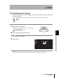
1. Switch to the setting mode.
STILL/LIVE MODE
Hold down the center button for more than two seconds to
UP
activate the setting mode.
TRIG
EXECUTE DOWN
Hold down for more
than two seconds.
“Changing Settings” p.24
Setting item
Store Mode
Settings
Details
NG only*
Only the reading-failed images will be stored.
All
All the images will be stored.
The default settings are indicated with an asterisk (*).
4. Select [OK] to close the [Image Store] menu.
Section 4 Viewing the Images Read in the Past
2. Select [System Setting] [Image Store] [Store Mode] from [Setting Menu].
3. Select the images to be stored.
The [System Setting] menu will be displayed.
V400-F050/250/350
User’s Manual
55
Section 4
Other Settings
Saving/Initializing All the Settings
This section explains how to save all the settings including reading conditions and system
settings, as well as initializing them to the factory settings.
Saving All the Settings
Save all the settings including reading conditions and system settings to the internal
ROM as follows. Once they are saved to the internal ROM, they will not be deleted
even if the power is turned OFF.
Section 4 Saving/Initializing All the Settings
1. Switch to the setting mode.
Hold down the center button for more than two seconds to
activate the setting mode.
“Changing Settings” p.24
2. Select [Save] from [Setting Menu].
A confirmation menu will appear.
3. Select [OK].
All the settings will be saved, and the [Setting Menu] will reappear.
56
V400-F050/250/350
User’s Manual
STILL/LIVE MODE
UP
TRIG
EXECUTE DOWN
Hold down for more
than two seconds.
Section 4
Other Settings
Initializing All the Settings
Reset all the settings including reading conditions and system settings to the factory
settings as follows.
To initialize reading conditions individually, select [Delete] from the [Bank Setting] menu.
p.40
1. Switch to the setting mode.
Hold down the center button for more than two seconds to
activate the setting mode.
UP
TRIG
EXECUTE DOWN
Hold down for more
than two seconds.
Section 4 Saving/Initializing All the Settings
“Changing Settings” p.24
STILL/LIVE MODE
2. Select [Initialize] from [Setting Menu].
A confirmation menu will appear.
3. [Select [OK].
All the settings will be initialized to the factory settings, and the [Setting Menu] will reappear.
V400-F050/250/350
User’s Manual
57
Section 4
Other Settings
Displaying the Version Information
Display the software version as follows.
1. Switch to the setting mode.
Hold down the center button for more than two seconds to
activate the setting mode.
“Changing Settings” p.24
STILL/LIVE MODE
UP
EXECUTE DOWN
Hold down for more
than two seconds.
2. Select [System Setting] [Version Information] from [Setting Menu].
Section 4 Displaying the Version Information
58
The version information appears.
3. Select [Exit].
The [System Setting] menu will reappear.
V400-F050/250/350
User’s Manual
TRIG
Section 5
Communicating with PC and
Programmable Controller
This section explains the commands required to make a connection and
communicate with a PC or programmable controller via RS-232C or discrete I/O.
RS-232C Communication
60
Wiring Diagram
60
List of Commands
62
Internal Specifications
73
74
Description of I/O Terminals
75
Timing Charts
76
V400-F050/250/350
User’s Manual
Section 5 Communicating with PC and Programmable Controller
Discrete I/O Communication
59
Section 5
Communicating with PC and Programmable Controller
RS-232C Communication
It is possible to input a reading trigger and output reading results via RS-232C.
This section explains connecting method and commands.
For the setting method of communication mode and conditions, refer to “Setting
Communication Conditions” (p.44).
Wiring Diagram
PC
A D-SUB 9-pin connector (female) is used for the cable type V400-W24 (NPN type)
and V400-W24P (PNP type). The connector is compatible with the connection port on
the DOS/V PC.
2D code reader
V400-F050/250/350
POWER
OK
Section 5 RS-232C Communication
STILL/LIVE MODE
UP
Cable
V400-W24 (NPN type)
V400-W24P (PNP type)
NG
TRIG
EXECUTE DOWN
CN1
CN2
Power
supply
device
Omron Corporation
PC
24VDC
Recommended: OMRON
S8VS-03024
2D code reader
V400-F050/250/350
Special round connector
DOS/V PC
D-sub, 9-pin
Name
Pin No.
Name
-
1
SD
RD
2
RD
SD
3
+24V
ER
4
GND
SG
5
TRIG
DR
6
RESET
RS
7
RUN
CS
8
OK/NG
-
9
ERROR
Shield wire
Connector cover
BUSY
+24 V (Brown)
0 V (Blue)
Not used with RS-232C
communication.
TRIG (Pink)
RESET (Orange)
RUN (Green)
OK/NG (Black)
ERROR (Gray)
BUSY (Yellow)
(View of mating section)
60
V400-F050/250/350
User’s Manual
Section 5
Communicating with PC and Programmable Controller
Programmable Controller
A D-SUB 9-pin connector (male) is used for the cable type V400-W23 (NPN type) and
V400-W23P (PNP type). The connector is compatible with the connection port on
OMRON CJ-series and CS-series Programmable Controller.
2D code reader
V400-F050/250/350
POWER
OK
STILL/LIVE MODE
UP
Cable
V400-W23 (NPN type)
V400-W23P (PNP type)
NG
TRIG
EXECUTE DOWN
CN1
CN2
Power
supply
device
Omron Corporation
24VDC
Programmable controller
CJ Series
CS Series
Recommended: OMRON
S8VS-03024
2D code reader
V400-F050/250/350
Special round connector
Programmable controller
D-sub, 9-pin
Name
Pin No.
-
1
SD
SD
2
RD
RD
3
+24V
RS
4
GND
CS
5
TRIG
-
6
RESET
-
7
RUN
-
8
OK/NG
SG
9
ERROR
Shield wire
Connector cover
BUSY
+24 V (Brown)
0 V (Blue)
Not used with RS-232C
communication.
TRIG (Pink)
RESET (Orange)
RUN (Green)
OK/NG (Black)
ERROR (Gray)
BUSY (Yellow)
Section 5 RS-232C Communication
Name
(View of mating section)
V400-F050/250/350
User’s Manual
61
Section 5
Communicating with PC and Programmable Controller
List of Commands
Communication is carried out via RS-232C using the following commands while the
reading screen is active.
Commands that Control Controller Operations
Use the following commands to instruct the controller to perform certain operations,
such as executing reading and switching reading condition.
Command
Section 5 RS-232C Communication
62
Function
Page
GL
Performs one reading.
p.64
GO
Performs a level trigger.
p.64
SO
Stops the level trigger.
p.64
GC
Performs continuous reading.
p.65
SC
Stops continuous reading.
p.65
RD
Outputs the previous send data (polling).
p.65
DC
Switches the image display mode (still image/real-time image).
p.66
GM
Switches the currently used trigger mode.
p.67
SN
Confirms/switches reading condition.
p.68
GT
Performs teaching.
p.68
LC
Switches the light to be turned ON from one to another.
p.69
LT
Adjusts the exposure time.
p.70
FT
Performs teaching without changing the exposure time.
p.70
VR
Checks the software version.
p.71
Commands that Save and Load Data
Use the following commands to back up the settings you made to the code reader or
PC.
Command
Function
CB
Backs up the setting data to the PC.
p.71
CU
Loads the setting data from the PC.
p.71
SV
Saves the setting data to the flash memory.
p.72
V400-F050/250/350
User’s Manual
Page
Section 5
Communicating with PC and Programmable Controller
Description of Format
Commands must be input in ASCII code. They can be input in either upper-case or
lower-case.
Header
Command
1
2
No.
Item
Number of
characters
1
Header (Prefix)
1
Input
Parameter
FCS
4
5
3
Footer
6
Settings
Enter the symbol that indicates the beginning of the command format.
This item is not available if [None] is selected for [Prefix] setting mode.
p.47
2
Command
2
These characters indicate the operation content.
3
Space
1
A space must be inserted between the command (2) and parameter (4).
4
Parameter
5
FCS
(Frame check
sequence)
2
Footer(Suffix)
1 to 2
This parameter needs to be specified depending on the command (3).
If needed, enter a numerical value.
Specify the FCS to be used.
This item is not available if [OFF] is selected for [FCS] setting mode.
p.47
Enter the symbol that indicates the end of the command format.
p.47
In the explanation of the format for each command, only the items “command (2)” to “parameter (4)”
are given.
Output
Header
Content of reply FCS
Footer
Number of read data digits Code quality Read data
1
2
Section 5 RS-232C Communication
6
Not fixed
3
• In the explanation of the format for each command, only “content of reply” when a command is
executed correctly is given.
• The content of reply when a command is not executed will be
No.
Item
1
Number of read
data digits (Digit
Data)
Number of
characters
2 or 4
E
R
.
Settings
Returns the number of reading data digits.
The number of characters must be set in [Digit Data] of the setting mode. This
item is not available if [OFF] is set.
p.47
2
Code quality
(Checker Data)
12
Returns the code quality of the read data.
This item is not available if [OFF] is selected for [Checker Data] setting mode.
p.47
3
Read data
Depends on Returns the read data.
the read data.
V400-F050/250/350
User’s Manual
63
Section 5
Communicating with PC and Programmable Controller
Data Format for Each Command
GL
Function... Performs one reading.
Reading is executed with the retry condition that is set when a trigger is
input.
“Number of read data digits” and “Code quality” are output only if they
are set.
p.47
Input
Output
G
L
• When reading is successful
Read data
• When reading has failed
G
?N Error
Code
Section 5 RS-232C Communication
GO
Function... Execute a level trigger.
“Number of read data digits” and “Code quality” are output only if they
are set.
p.47
Input
Output
G O
• When reading is successful
Read data
• When reading has failed
G
?N Error
Code
Reading is repeated until it is successful.
SO
Function... Stops the level trigger.
This command is effective only when a level trigger is being executed.
64
Input
S O
Output
O K
V400-F050/250/350
User’s Manual
Section 5
Communicating with PC and Programmable Controller
GC
Function... Performs continuous reading.
“Number of read data digits” and “code quality” are output only if they
are set.
p.47
Input
Output
G C
• When reading is successful
Read data
• When reading has failed
G
?N Error
Code
Data is output each time reading is executed.
SC
This command is effective only when a continuous trigger is being
executed.
Input
Output
S
C
O K
RD
Function... Outputs the previous send data. (Polling command)
Section 5 RS-232C Communication
Function... Stops continuous reading.
Use this command to resend data that has been lost due to
communication error.
Input
Output
R D
• When reading is successful
Read data
• When reading has failed
G
?N Error
Code
V400-F050/250/350
User’s Manual
65
Section 5
Communicating with PC and Programmable Controller
DC
Function 1... Checks the monitor image display mode (still image/real-time image).
Input
Output
D C
O
K
Image display
state
Image display state
Details
0
Switches to still image.
1
Switches to real-time image.
Function 2... Switches the monitor image display mode (still image/real-time image).
Section 5 RS-232C Communication
66
Input
D
C
Image display state
Enter the image display state.
Image display
state
Output
V400-F050/250/350
User’s Manual
Details
0
Switches to still image.
1
Switches to real-time image.
O K
Section 5
Communicating with PC and Programmable Controller
GM
Function 1... Checks the currently used trigger mode.
Input
Output
G M
O
K
Trigger mode
Function 2... Switches the trigger mode.
Only the mode is switched (no trigger is input).
Input
G
M
Trigger mode
Set the desired trigger mode as shown below.
Trigger mode
One-shot trigger
1
Continuous trigger
2
Level trigger
O K
If the level trigger is selected, error code for reading failure will not be output.
V400-F050/250/350
User’s Manual
Section 5 RS-232C Communication
Output
Details
0
67
Section 5
Communicating with PC and Programmable Controller
SN
Function 1... Checks the currently used reading condition No. (Bank #00 to #09).
Input
S
N
Output
O
K
Reading condition No.
Function 2... Switches the reading condition No. (Bank #00 to #09) to be used.
Input
S
N
Reading condition No.
Set a reading condition No. (0 to 9).
Output
O K
Section 5 RS-232C Communication
GT
Function... Performs teaching.
Input
G
T
Reading condition No.
Set a reading condition No. (0 to 9).
If no reading condition No. is specified, the currently used bank will be
overwritten with the teaching results.
Output
• When teaching is successful
O K
• When teaching has failed
G
?N Error
Code
68
V400-F050/250/350
User’s Manual
Section 5
Communicating with PC and Programmable Controller
LC
Function 1... Checks the lighting state.
Input
L
C
Output
O
K
Lighting state
Lighting state
Details
For V400-F050
For V400-F250/350
0
The light connected to the left
connector (L) is ON.
The light is ON.
1
The light connected to the right
connector (R) is ON.
The light is OFF.
2
The light is OFF.
The light is OFF.
Input
L
C
Light
Specify the light to be turned ON.
Light
Output
Details
For V400-F050
For V400-F250/350
0
Turns ON the light connected to
the left connector (L).
Turns ON the light.
1
Turns ON the light connected to
the right connector (R).
Turns OFF the light.
2
Turns OFF the light.
Turns OFF the light.
Section 5 RS-232C Communication
Function 2... Switches the light to be turned ON from one to another.
O K
V400-F050/250/350
User’s Manual
69
Section 5
Communicating with PC and Programmable Controller
LT
Function 1... Checks the exposure time.
Input
L
T
Output
O
K
Exposure time
The exposure time is output with a 4-digit numerical value at 1/100 msec.
If the exposure time is set automatically, "OK AUTO" is output.
Example: When the exposure time is 5.47 msec.
OK 0547
Function 2... Adjusts the exposure time.
Input
L
T
Exposure time
Section 5 RS-232C Communication
Enter the exposure time with a 4-digit numerical value.
To automatically set the exposure time, enter "LT AUTO".
Output
O
K
The value specified with the LT command causes a difference of max. 0.04 msec. However, it
will not affect the reading process.
FT
Function... Performs teaching without changing the exposure time.
The exposure time is fixed to the currently set value.
Input
F
T
Reading condition No.
Specify the reading condition No. between 0 and 9.
If no reading condition No. is specified, the currently used bank will be
overwritten with the teaching results.
Output
• When teaching is successful
O K
• When teaching has failed
G
?N Error
Code
70
V400-F050/250/350
User’s Manual
Section 5
Communicating with PC and Programmable Controller
VR
Function... Checks the version information.
Input
V
R
Output
1
.
0
0
* The above value is given as an example.
CB
Function... Backs up the setting data to the PC.
Input
C
Backup source
B
Specify the data to be backed up.
Backup source
R
AL
All data
SY
System data
BK
All reading condition data
B0 to 9
Corresponding reading condition data
00 to 27
Corresponding image No.
E
A
D
Y
After “READY” is output, the main unit switches to XMODEM
communication automatically, and outputs O K when communication
is completed successfully.
CU
Function... Loads the setting data from the PC.
Input
C
Section 5 RS-232C Communication
Output
Details
Upload source
U
Specify the data to be uploaded from the PC.
Upload source
Output
R
Details
AL
All data
SY
System data
BK
All reading condition data
B0 to 9
Corresponding reading condition data
00 to 27
Corresponding image No.
E
A
D
Y
After “READY” is output, the controller switches to XMODEM
communication automatically, and outputs O K when communication
is completed successfully.
V400-F050/250/350
User’s Manual
71
Section 5
Communicating with PC and Programmable Controller
SV
Function... Saves the reading conditions and system settings to the flash memory
of the reader.
Input
Output
Section 5 RS-232C Communication
72
V400-F050/250/350
User’s Manual
S
V
O K
Section 5
Communicating with PC and Programmable Controller
Discrete I/O Communication
It is possible to execute reading from the programmable controller and output reading result
(OK/NG) via discrete I/O.
For the setting method of communication mode and conditions necessary to communicate via
discrete I/O, refer to “Setting Discrete I/O Communication Conditions” (p.48).
Connecting Diagram
Cable
V400-W23/W24 (NPN type)
V400-W23P/W24P (PNP type)
2D code reader
V400-F050/250/350
POWER
OK
STILL/LIVE MODE
UP
NG
TRIG
EXECUTE DOWN
CN1
CN2
Power
supply
device
Omron Corporation
24VDC
Programmable controller
CJ Series
CS Series
Recommended: OMRON
S8VS-03024
Cable and signal assignment on the main unit are shown below. Just wire only
necessary terminals.
2D code reader
V400-F050/250/350
Special round connector
Name
TRIG
RESET
Description
Discrete I/O
Wire color
Input signal: Reading trigger signal
Pink
Input signal: Restart
Orange
Output signal: Output while the reading screen is
displayed.
Green
OK/NG
Output signal: (OK) (reading is successful) or (NG)
(reading fails) is output.
Black
ERROR
Output signal: Output when an error occurs.
Gray
BUSY
Output signal: Output while processing is in
progress.
Yellow
RUN
Section 5 Discrete I/O Communication
Cable Wiring
* The brown and blue wires must be connected to the power supply device.
V400-F050/250/350
User’s Manual
73
Section 5
Communicating with PC and Programmable Controller
Internal Specifications
Input specifications
Item
Specifications
Cable model
V400-W23/24 (NPN type)
Input voltage
12 to 24V ±10%
Input ON current *1
5 to 15 mA
Input ON voltage *1
7 V min.
V400-W23P/24P (PNP type)
Input OFF current *2 0.1 mA max.
Input OFF voltage *2 5 V max.
Input ON delay
RESET: 10 msec max.
TRIG: 0.5 msec max.
Input OFF delay
RESET: 15 msec max.
TRIG: 0.5 msec max.
Internal circuit
diagram
Input terminal
(TRIG, RESET)
24V (Brown)
12 V to
24 V DC
24 VDC
Section 5 Discrete I/O Communication
Input terminal
(TRIG, RESET)
GND (Blue)
*1: ON current/ON voltage
This refers to the current or voltage values needed to shift from the OFF ON state.
The ON voltage value is the following potential difference.
• NPN type: Potential difference between 24 V terminal and input terminal
• PNP type: Potential difference between input terminal and GND terminal
*2: OFF current/OFF voltage
This refers to the current or voltage values needed to shift from the ON OFF state.
The OFF voltage value is the following potential difference.
• NPN type: Potential difference between 24 V terminal and input terminal
• PNP type: Potential difference between input terminal and GND terminal
Output specifications
Item
Specifications
Cable model
V400-W23/24 (NPN Type)
Output voltage
12 to 24 V ±10%
Output load current
45 mA max.
ON residual voltage
1.5 V max.
OFF leakage current
0.1 mA max.
Internal circuit
Output
terminal
GND (Blue)
V400-F050/250/350
User’s Manual
24 V (Brown)
24 V (Brown)
Load
74
V400-W23P/24P (PNP Type)
24 VDC
Output
terminal
Load
GND (Blue)
24 VDC
Section 5
Communicating with PC and Programmable Controller
Description of I/O Terminals
Terminal
Input
Output
Description
TRIG
Inputs a reading trigger from a photoelectric sensor etc.
Make sure that the TRIG is ON for at least 0.5 ms.
The interval at which the TRIG can be input depends on the reading time.
The BUSY signal is output during reading process to disable input of the
TRIG.
RESET
Resets the controller.
RUN
This signal is ON while V400-F050/250/350 is active.
OK/NG
Outputs OK when reading is successful, and outputs “NG” when reading
has failed.
It is also possible to specify whether the signal is to be output when
reading is successful or when reading has failed.
p.49
ERROR
This signal is turned ON when an error occurs.
BUSY
This signal is turned ON while the controller is performing reading.
TRIG and commands will not be accepted while the BUSY signal is ON.
Section 5 Discrete I/O Communication
V400-F050/250/350
User’s Manual
75
Section 5
Communicating with PC and Programmable Controller
Timing Charts
When [One Shot] is Selected as Trigger Mode and [OK Pulse] is
Selected for [OK/NG Output]
The OK/NG signal is not output when reading has failed.
• If [NG Pulse] is selected for [OK/NG Output], the OK/NG signal will not be output when reading is
successful.
• If [OFF] is selected for [NG Output], no outputs will be made via RS-232C when reading has failed.
Power ON
Completion of start-up
Power OFF
RUN
OFF
ON
Reader is active.
TRIG
OFF
Section 5 Discrete I/O Communication
76
ON
Trigger input
Trigger input
Trigger input
BUSY
OFF
ON
Reading in progress
Reading in progress
Reading in progress
OK/NG
OFF
ON
By pulse width
(RS-232C)
Serial communication in progress
V400-F050/250/350
User’s Manual
Serial communication in progress
Serial communication in progress
Section 5
Communicating with PC and Programmable Controller
When [One Shot] is Selected as Trigger Mode and [Level] is
Selected for [OK/NG Output]
The OK and NG signals are expressed as level signals.
The signals are input when the BUSY signal switches from ON to OFF.
If [OFF] is selected for [NG Output], no outputs will be made via RS-232C when reading has failed.
Power ON
Completion of start-up
Power OFF
RUN
OFF
ON
Reader is active.
TRIG
OFF
ON
Trigger input
Trigger input
BUSY
OFF
ON
Reading in progress
Reading in progress
Reading in progress
OK/NG
OFF
ON
(RS-232C)
Serial communication in progress
Serial communication in progress
Serial communication in progress
Section 5 Discrete I/O Communication
Trigger input
If [Level] is selected for [OK/NG Output], this signal is turned ON/OFF to indicate the reading result
(i.e. whether reading is successful or has failed).
The signal is ON when reading is successful, and it is OFF when reading has failed.
V400-F050/250/350
User’s Manual
77
Section 5
Communicating with PC and Programmable Controller
When [Level] is Selected as Trigger Mode and [OK Pulse] is
Selected for [OK/NG Output]
Reading is repeated while the TRIG signal is ON until reading is successful, and
reading is exited when it is successful.
Therefore, this setting executes one output per trigger input.
If the TRIG signal is turned OFF before reading is successful, reading failure will result.
Even if an item other than [NG Pulse] is selected for [OK/NG Output], this signal will perform the
same operation as when [One Shot] is selected.
Power ON
Completion of start-up
Power OFF
RUN
OFF
ON
Reader is active.
TRIG
Section 5 Discrete I/O Communication
78
OFF
ON
Trigger input
Trigger input
Trigger input
BUSY
OFF
ON
Reading in progress (NG)
Reading in progress (NG) Reading in progress (OK)
OK/NG
OFF
ON
By pulse width
(RS-232C)
Serial communication in progress
V400-F050/250/350
User’s Manual
Section 5
Communicating with PC and Programmable Controller
When [Continuous] is Selected as Trigger Mode and [OK Pulse] is
Selected for [OK/NG Output]
Reading and result output are repeated while the TRIG signal is ON.
The BUSY signal will remain ON while reading is executed repeatedly.
With this setting, correct detection is not possible if [Level] is selected for [OK/NG Output]. Set [OK
Pulse] or [NG Pulse] for [OK/NG Output].
Power ON
Completion of start-up
Power OFF
RUN
OFF
ON
Reader is active.
TRIG
OFF
ON
Trigger input
OFF
ON
Reading in progress
Reading in progress
Reading in progress
OK/NG
OFF
ON
By pulse width
(RS-232C)
Serial communication in progress
Serial communication in progress
Serial communication in progress
V400-F050/250/350
User’s Manual
Section 5 Discrete I/O Communication
BUSY
79
Section 5
Communicating with PC and Programmable Controller
MEMO
Section 5 Discrete I/O Communication
80
V400-F050/250/350
User’s Manual
Section 6
Troubleshooting
This section explains the countermeasures to take when reading cannot be
executed correctly or when a problem occurs.
Error Codes and Corrective Actions
82
Troubleshooting
82
Connection Errors
82
Reading Errors
82
Discrete I/O Errors
83
RS-232C Errors
83
Section 6 Troubleshooting
V400-F050/250/350
User’s Manual
81
Section 6
Troubleshooting
Error Codes and Corrective Actions
This section lists the error codes that may be displayed on the screen when reading fails,
along with their corrective actions. They are given in error code order.
Error Code
Action
?E000
2D code cannot be found, possibly due to uneven background. Check the workpiece surface and
lighting condition.
?E100
2D code cell cannot be recognized correctly. Check the marking and lighting conditions, and then
perform teaching again.
?E200
Reading was not completed within the specified period of time. Check the workpiece and lighting
condition, then perform teaching again.
Increase the reading timeout value.
Troubleshooting
Connection Errors
Symptom
Action
Section 6 Error Codes and Corrective Actions
The POWER indicator is not
lit.
• Is the power supply device connected properly?
p.20
Monitor image is not clear.
• Is the monitor cable connected correctly?
p.20
No images are displayed on
monitor.
(For V400-F050)
• Is the lens cap removed?
p.21
No codes are displayed on
monitor.
• Press the left button to switch to the real-time image, or execute
No menu is displayed.
• Hold down the center button for more than two seconds.
• Is power current capacity sufficient?
• Is the lens attached correctly?
teaching and check the image.
p.22
p.30
p.24
Reading Errors
Symptom
Not possible to read, though
teaching was successful.
Action
• Does the teaching condition match the code conditions?
Code type
Symbol size
Mirror status
Reverse
• Check the content of the bank.
82
Page
V400-F050/250/350
User’s Manual
Page
p.30
Section 6
Troubleshooting
Discrete I/O Errors
Symptom
Failed to respond to signals
from input terminals.
Action
Page
• Is the signal cable wired correctly?
p.73
No signal is output from output • Is the signal cable wired correctly?
terminal.
p.73
RS-232C Errors
Symptom
Cannot communicate.
Action
Page
• Is the cable connected correctly?
• Is the correct communication mode selected?
p.20
p.44
p.45
• Switch to the communication display.
p.52
• Do the communication specifications match those of the host device?
Communication status is
unknown.
Communication status is displayed in the left area of the monitor
screen.
Section 6 Troubleshooting
V400-F050/250/350
User’s Manual
83
Section 6
Troubleshooting
MEMO
Section 6 Troubleshooting
84
V400-F050/250/350
User’s Manual
Appendix
Lens and Lighting
86
Light and Lens V400-F050
86
Line Speed and Reading Time/Exposure Time
91
Exposure Time
91
Reading Time
92
Maintenance
Handling the Code Reader
Inspection
93
93
93
94
ASCII Table
99
Ladder Programming Example for Connecting to a PLC 100
FCS Check Program Example (BASIC)
104
Data Capacity Table
106
Menu Hierarchy
109
V400-F050/250/350
User’s Manual
Appendix
Specifications and Dimensions
85
Appendix
Lens and Lighting
Please note that the field of vision and installation distance differ between V400-F250 and
V400-F350.
When choosing a lens and light for V400-F050, refer to the explanation given below.
Light and Lens V400-F050
If V400-F250/350 do not meet the requirements of field of vision and installation
distance, use V400-F050, which is a C-mount type and allows connection of an
external light. Refer to the following to choose the appropriate light and lens.
Lights
The following Moritex lights are recommended.
* Refer to the following website for details on Moritex products.
http://www.moritex.co.jp/home/english/index.html
Back lights
A stable, high-contrast image can be obtained.
Model
Appendix Lens and Lighting
MEBL-CR25
Red
25 × 25
MEBL-CG25
Green
25 × 25
MEBL-CB25
Blue
25 × 25
MEBL-CR50
Red
50 × 50
MEBL-CG50
Green
50 × 50
MEBL-CB50
Blue
50 × 50
Reflected lights
Partially reflecting workpieces can be read.
The lights to be used are the same as those used for
back lighting.
86
Emitting Emitting size
color
V400-F050/250/350
User’s Manual
Appendix
Ring lights
Light can be shone uniformly on workpieces.
Direct ring light
Model
Emitting
color
Inner ring
diameter
Outer ring
diameter
Emitting
angle
MDRL-CR16
Red
Ø16
Ø48
76°
MDRL-CR28
Red
Ø28
Ø50
75°
MDRL-CR31
Red
Ø31
Ø66
75°
MDRL-CR35
Red
Ø35
Ø70
90°
Emitting
color
Inner ring
diameter
Outer ring
diameter
Emitting
angle
Red
Ø48
Ø74
30°
Low-angle ring light
Model
MLRL-CR48
Coaxial light
A stable image can be obtained with few shadows from uneven surfaces on
workpieces.
Model
Adapter
Base
Box height
(mm)
Light path
extension distance
(mm)
MSCL-CR24
Red
24
6.8
MSCL-CG24
Green
24
6.8
MSCL-CB24
Blue
24
6.8
MSCL-CR39
Red
39
1.2
MSCL-CG39
Green
39
1.2
MSCL-CB39
Blue
39
1.2
Attach the following bases and adapters.
Model
MLA-SCM255
MLA-SCM270
Coaxial
light
Type
M25.5P0.5 lens
Adapter
MLA-SCM305
MLA-SCBS
Applicable lens
M27P0.5 lens
M30.5P0.5 lens
Base
Appendix Lens and Lighting
Lens
Emitting
color
-
V400-F050/250/350
User’s Manual
87
Appendix
Setting the Field of Vision and Working Distance
Refer to the following formula to calculate the field of vision and working distance.
(Code size: C) + 2 × (Cell size: S) < (Field of vision: A) < 121 × (Cell size: S)
Number of effective
pixels of camera
640 (H) × 480 (V)
Code size
C (mm)
Symbol size
M×M
(Cell size)
S (mm) = C/M
4 pixels/cell required
A margin for one cell is required.
Field of vision
Max.: A (mm) = S/4 × 480
Min.: A (mm) = C + S × 1 × 2
S
C
A
Set an appropriate field of vision with workpiece positioning accuracy taken into
account.
Example: When the code size is 3 mm and the symbol size is 12 × 12
• Cell size: S = 3/12 = 0.25 mm
• Max. field of vision: 0.25/4 × 480 = 30 mm
• Min. field of vision: 3 + 0.25 × 1 × 2 = 3.5 mm
If the positioning accuracy is ±5 mm, the field of vision must be set between
Appendix Lens and Lighting
88
13.5 mm or higher and below 30 mm.
V400-F050/250/350
User’s Manual
Appendix
Selecting a Lens
Select a lens according to the required field of vision and working distance between the
workpiece and lens.
•The longer the extension tube, the lower the brightness.
•The longer the working distance, the larger the depth of field.
•Make sure that the working distance can be adjusted since there are individual
differences among cameras.
CCTV lens
The following Moritex lenses are recommended.
* Refer to the following website for details on Moritex products.
http://www.moritex.co.jp/home/english/index.html
CCTV Lenses and Dimensions
CCTV lens
Model
ML-0614
ML-0813
ML-1214
ML-1614
ML-2514
External
dimensions
Lock
mechanism
With focus/diaphragm lock mechanism
Appendix Lens and Lighting
Mount
C-mount
Model
ML-3519
ML-5018
ML-7527
ML-10035
External
dimensions
Lock
mechanism
Mount
With focus/diaphragm lock mechanism
C-mount
Extension tube
Model
ML-EXR
Configuration
Thickness: 7 rings/set (0.5 mm, 1 mm, 2 mm, 5 mm, 10 mm, 20 mm, 40 mm)
V400-F050/250/350
User’s Manual
89
Appendix
The table below shows the field of
vision and working distance for each
lens when an extension tube is
attached to the lens.
V400-F050
Extension tube (mm)
Lens
Working distance:
WD (mm)
Workpiece
Field of vision (mm)
(Unit: mm)
ML-0813 ML-1214 ML-1614 ML-2514 ML-3519 ML-5018 ML-7527 ML-10035
Exten- ML-0614
sion Field
Field
Field
Field
Field
Field
Field
Field
Field
tube
of
of
of
of
of
of
of
of
of
WD
WD
WD
WD
WD
WD
WD
WD
WD
(mm) vision
vision
vision
vision
vision
vision
vision
vision
vision
0
124.0
200.0
72.0
147.7
77.0
247.7
81.8
357.8
0.5
44.6
32.8
63.2
43.0
57.4
31.9
115.2
59.0
89.1
41.3
289.2
125.0
116.7
48.1
514.6
206.1
1
22.3
18.9
24.8
19.0
28.7
20.5
51.8
33.7
44.6
28.2
135.9
80.0
58.4
34.1
251.8
142.8
90.6
37.8
636.5
268.5
19.1
15.1
30.6
21.7
29.7
21.4
84.9
56.7
38.9
26.4
164.2
108.2
60.4
31.3
425.3
222.8
83.8
31.0
833.8
323.9
115.1 1576.5
42.6 609.9
22.3
17.3
59.3
42.4
29.2
21.5
120.3
86.3
45.3
26.7
319.7
190.6
62.8
27.6
630.7
290.9
86.3 1193.0
37.9 547.6
5
11.7
10.2
41.5
35.4
18.1
14.2
129.6
103.1
25.1
16.6
265.1
184.8
34.5
22.9
502.6
347.0
55.3 1421.7
22.6 607.0
71.3 2412.7
20.5 724.2
10
5.8
5.4
15.2
14.0
9.1
8.0
66.3
59.6
12.6
10.0
143.2
120.6
17.3
13.8
272.5
225.7
27.6
15.1
832.7
474.7
35.7 1431.6
14.3 608.6
15
6.0
5.5
45.2
42.7
8.4
7.2
102.6
93.0
11.5
9.8
195.8
173.5
18.4
11.4
636.3
408.4
23.8 1104.6
11.3 545.7
20
4.5
4.2
34.6
33.6
6.3
5.6
82.2
77.6
8.6
7.7
157.5
144.5
13.8
9.1
538.2
368.5
17.8
9.2
941.0
505.3
5.0
4.6
70.1
67.8
6.9
6.3
134.4
126.0
11.1
7.6
479.2
341.9
14.3
7.8
842.9
478.1
30
5.8
5.3
119.1
113.1
9.2
6.5
440.0
322.8
11.9
6.7
777.5
457.6
35
4.9
4.6
108.1
103.7
7.9
5.7
411.9
308.5
10.2
5.9
730.8
442.6
40
4.3
4.1
99.9
96.5
6.9
5.1
390.9
297.4
8.9
5.3
695.8
430.1
45
6.1
4.6
374.5
288.5
7.9
4.8
668.5
420.7
50
5.5
4.1
361.4
281.3
7.1
4.4
646.7
412.3
5.9
3.7
614.0
400.1
1.5
2
Appendix Lens and Lighting
25
64.9
457.7
181.2 1270.0
47.8 338.2
49.1
500.0
67.6
943.0
45.0 1000.0
34.8 1000.0
251.4 2458.7
41.1 422.1
125.7 1240.0
35.3 366.1
138.2 3188.9
32.3 776.1
60
Source: Lenses, lighting, and peripheral devices for image processing catalog from Moritex
Note: Since values shown in the table are calculated values they may differ from actual measured values.
They must be used as your reference.
90
V400-F050/250/350
User’s Manual
Appendix
Line Speed and Reading Time/Exposure Time
The following points must be observed when reading moving workpieces.
• Make sure that the still image display mode is constantly selected.
Exposure Time
To eliminate image blurring and stabilize reading, refer to the following formula to set
the lower limit of exposure time.
(Moving shift tolerance: W)
(Exposure time: T)
(Max. line speed: V)
W
0.1 ×
Exposure time
T (s)
Code size
C (mm)
Symbol size
M
Field of vision
A (mm)
Number of image
pickup pixels
(Moving direction)
N
Pixels/cell
n = (C × N)/(A × M) *1
(Code size: C)
(Symbol size: M)
C
Reading time
R (s)
Code pitch
L (mm)
Line speed
V (mm/s)
A
*1: “Pixels/cell > 4” must be satisfied with sufficient margin taken into account.
*2: The moving shift tolerance is 10% of the cell size.
Example: When V = 60 mm/s, C = 1.6 mm, M = 16, A = 10 mm, N = 512, R = 300 ms
and L = 30 mm
The exposure time is calculated as follows, which will not cause problems
with reading.
n
1.6 × 512
(10 × 16)
= 5.12 > 4
The exposure time is as follows.
T
0.1 × 1.6
(16 × 60)
= 0.17 msec
V400-F050/250/350
User’s Manual
Appendix Line Speed and Reading Time/Exposure Time
Moving shift tolerance W = C/M × 0.1 (mm) *2
91
Appendix
If the exposure time does not meet the following, the image will be blurred causing adverse effects
on reading.
W
T
V
=
0.1 C
(MV)
If you want to set the exposure time, hold down the left button for more than two
seconds to change the current one or set it in the setting mode.
p.22, p.32
Reading Time
The reading time can be calculated using the formula below.
(Reading time: R)
(Code pitch: L)
(Max. line speed: V)
If the reading time does not meet this formula, the code will be outside the field of vision
so the code cannot be read even if the requirement of exposure time is satisfied.
Example: When the line speed is 60 mm/s and code pitch is 30 mm
Appendix Line Speed and Reading Time/Exposure Time
92
R
30
60
= 0.5 s = 500 ms
The above calculation indicates that the code cannot be read unless the
reading time is 500 ms or shorter.
If the reading time is 500 ms or longer, the line speed must be decreased or
the code pitch increased.
V400-F050/250/350
User’s Manual
Appendix
Maintenance
Handling the Code Reader
The main unit, lens and light are optical components. so they must be handled
carefully.
If they get dirty or scratched, image pickup will deteriorate, disabling code reading.
•Do not touch the lens and light cover surface with your fingers or any pointed object.
•The code reader must be used in a dust-free environment.
If the lens or light cover get dirty, clean them with lens-cleaning cloth or air brush.
•When attaching a lens to the main unit (V400-F050), take care not to touch the CCD
pickup surface of the lens and not to let dust collect on it.
p.21
Inspection
To maintain the code reader in the best condition, perform the following regularly.
•Remove dirt from the lens and LED light using lens-cleaning cloth or air brush.
•Wipe off dirt on the main unit gently with a soft cloth.
Power supply
Details
Required tools
Measure the power supply voltage at the power terminal block,
and make sure that it is within the rated voltage range (21.6 to
26.4 VDC).
Multimeter
Ambient operating Measure the ambient operating temperature inside the cabinet,
temperature
and make sure that it is between 0 and +45 °C.
Thermometer
Ambient operating Measure the ambient operating humidity inside the cabinet, and
humidity
make sure that it is between 35% and 85% RH.
Hygrometer
Installation
condition
Cables and connectors connected to each device must be
correctly inserted and locked.
The lens must be secured firmly.
The lens mount must be secured firmly.
Appendix Maintenance
Inspection items
Screwdriver
• Turn OFF the power and take safety precautions before conducting maintenance or inspections.
• Do not use thinners or benzene to clean the code reader.
V400-F050/250/350
User’s Manual
93
Appendix
Specifications and Dimensions
Main unit
V400-F050
(Unit: mm)
Light
connector
(R-CH)
Power/
communication
connector
(84.1)
75.3
50
Monitor cable
connector
1.6
Ø11.5
40
Ø11.5
(13.1)
Light
connector
(L-CH)
1"-32UN-2A
(C-mount)
25.4
4-M3
Depth 5
(16.8)
25.4
26.8
V400-F250/350
Appendix Specifications and Dimensions
(Unit: mm)
(105.9)
50
97.1
Monitor cable
connector
Ø11.5
(13.1)
40
Ø11.5
48.6
25.4
94
Power/
communication
connector
V400-F050/250/350
User’s Manual
25.4
4-M3
Depth 5
(16.8)
Appendix
Mount seat
(Unit: mm)
31.6
4-holes (Ø3.4)
35.2
4-spot facing, Ø5.4, depth 2.2
2,
M
2-
44
D
1/4-20 UNC
through
t
ep
8
25.4
h
44
20
15
25.4
5
4
M
2th
u
ro
gh
General specifications
Model
External size
V400-F050
V400-F250
40 × 50 × 75 mm
V400-F350
40 × 50 × 97 mm
Focal length (WD)
Depends on the lens used.
Approx. 100 mm
Approx. 200 mm
Field of vision
Depends on the lens used.
Approx. 14 × 18 mm
Approx. 31 × 42 mm
Light
Up to two lights can be
directly driven.
Sensing element
Red LED
1/3-inch CCD
640 × 480 dots
Power supply voltage
24 VDC±10%
Power consumption
0.5 A max.
Insulation resistance
20 MΩ or higher
Dielectric strength
1000 V AC (1 minute)
Leakage current
0.25 mA max.
Noise resistance
Power line: 2 kVp-p; Pulse width: 50 ns; Rise time: 5 ns
Burst continuation time: 15 ms; Period: 300 ms
Vibration resistance
10 to 150 Hz at a single-amplitude of 0.35 mm (maximum acceleration: 50 m2/s),
10 times for 8 minutes each in 3 directions
Shock resistance
150 m/2; 3 times each in 6 directions
Operating ambient temperature
0 to +45 °C
Storage ambient temperature
-25 to +65 °C
Ambient humidity
25% to 85% RH (with no icing or condensation)
Ambient environment
Installation
Degree of protection
Weight
Appendix Specifications and Dimensions
Number of effective
pixels
No corrosive gases
Mount the reader with four M3 screws or fixture (supplied with the reader).
None
IP67 (IEC60529)
Approx. 150 g
V400-F050/250/350
User’s Manual
95
Appendix
Communication Cable
V400-W23/23P/24/24P
(Unit: mm)
L (Note 1)
39.8
500
50
50
20
Ø15.5.
12-pin round connector
D-sub 9-pin connector
Vinyl insulated round cord Ø6.8, 12 cores
Nameplate
Note 1: The cable length (L1) must be as follows.
Length L
General specifications
Model
I/F connector
Power supply wire
I/O type
Appendix Specifications and Dimensions
96
Operating ambient
temperature
Storage ambient temperature
Ambient humidity
Ambient environment
Materials
Minimum bending radius
Accessories
V400-F050/250/350
User’s Manual
V400-W23/P
V400-W24/P
D-sub 9-pin connector (male)
PLC connection type
D-sub 9-pin connector (female)
DOS/V PC connection type
Brown: +24V, Blue: GND
V400-W23, V400-W24: NPN
V400-W23P, V400-W24P: PNP
0 to +50 °C
-25 to +65 °C
25% to 85% RH (with no icing or condensation)
No corrosive gases
Cable sheath: Heat-resistant vinyl chloride
Special connector: PPS, PBT, POM
D-sub connector: ABS
42 mm
Ferrite core (×1)
Appendix
Monitor cable
V400-WM0
(Unit: mm)
Ø15.5.
Ø12.2
12-pin round connector
RAC Jack
L (See note 1.)
(See note 2.)
Vinyl insulated round cord Ø6.5, 3 cores
Nameplate
Note 1: The cable length (L1) must be as follows.
Length L
Note 2: These two wires are for a 24-V output.
Do not use them for input; doing so may
result in malfunction.
General specifications
Operating ambient temperature
Storage ambient temperature
Ambient humidity
Ambient environment
Materials
0 to +50 °C
−25 to +65 °C
25% to 85% RH (with no icing or condensation)
No corrosive gases
Cable sheath: Heat-resistant vinyl chloride
Special connector: PPS, PBT, POM
Appendix Specifications and Dimensions
V400-F050/250/350
User’s Manual
97
Appendix
Color LCD Monitor
F150-M05L-2D
(Unit: mm)
Mountable plate thickness 1.6 to 4.8
(46 max)
SYNC
132
143
POWER
(145)
(155)
Mounting fixture
(100)
185
42.2
(5.5)
• Tolerance: ±1 mm
174
Panel cutout
dimensions
mm
133.5 +0.5
0
mm
175.5+0.5
0
General specifications
Appendix Specifications and Dimensions
98
Power supply voltage
20.4 to 26.4 VDC
Current consumption
700 mA max.
Vibration resistance
10 to 150 Hz at a single-amplitude of 0.1 mm (maximum acceleration: 15 m/s2),
10 times for 8 minutes each in 3 directions
Shock resistance
150m/s2; 3 times each in 6 directions
Ambient temperature
Operating: 0 to +50°C; Storage: -25 to +65°C (with no icing or condensation)
Ambient humidity
Operating and storage: 35% to 85% RH (with no condensation)
Ambient environment
No corrosive gases
Degree of protection
IEC60529 IP20
Materials
Case: ABS/PC; Display surface: PMMA (Acrylic)
Weight
Approx. 610 g
Accessories
Mounting bracket (×4)
Performance Specifications
Panel size
5.5 inches (111.36 (H) × 83.52 (V) mm)
Panel type
TFT color liquid crystal display
Resolution
320 × 240 dots
Image pitch
0.348 (H) × 0.348 (V) mm
Contrast
85:1 (TYP)
Viewable angle
25° up/down and 50° left/right (with a contrast ratio > 10)
Luminance
250 cd/m2(TYP)
Backlight
Cold cathode fluorescent light
Response time
60 ms max.
Input signals
NTSC composite video (1.0 V/75 W termination)
V400-F050/250/350
User’s Manual
Appendix
ASCII Table
Data read using RS-232C is output as 2 ASCII characters.
The ASCII characters correspond to the following characters.
(Examples)
•When the read data is A, 41 is output.
•When the data read is T, 54 is output.
Lower 4 bits
Upper 4 bits
Appendix ASCII Table
V400-F050/250/350
User’s Manual
99
Appendix
Ladder Programming Example for Connecting
to a PLC
Connections Used in this Example
The following configuration is used in this example.
2D code reader
V400-F050/250/350
POWER
OK
STILL/LIVE MODE
UP
Cable
V400-W23 (NPN type)
V400-W23P (PNP type)
NG
TRIG
EXECUTE DOWN
CN1
CN2
Power
supply
device
Omron Corporation
24VDC
Programmable controller
CJ Series
CS Series
Recommended: OMRON
S8VS-03024
V400-F050/250/350 Settings (Default Settings)
Baud rate:
9,600 bps
Data length: 8 bits
Appendix Ladder Programming Example for Connecting to a PLC
100
Stop bits:
1 bit
Parity:
None
Header:
None
Footer:
CR
V400-F050/250/350
User’s Manual
Appendix
CS/CJ-series PLC Settings
Change the settings in the PLC Setup to those shown below using the CX-Programmer
and then transfer the settings to the CPU Unit of the PLC.
Communications Settings: Select the Custom Option and then set the baud rate to
9,600 and the format to “8,1,N”.
Mode: RS-232C
Start Code: Select Disable Option.
End Code: Select the Set End Code Option and set “000D”.
User’s Manual
Appendix Ladder Programming Example for Connecting to a PLC
V400-F050/250/350
101
Appendix
Sample Programming for CJ-series PLC Using a Software Trigger
With the following programming, the V400-F will start reading when the Read Start Bit
(CIO 0.00) turns ON. The reading results will be stored in DM200 to DM220.
A200.11
MOV(021)
First
Cycle Flag
#474C
Stores SEND command (GL ('474C'))
in DM000.
D0
0.00
DIFU(013)
Read
Start Bit
W0.00
W0.00 A392.05
Work bit
Send
Ready
Flag
TXD(236)
D0
#0000
Turns ON W0.00 when CIO 0.00 turns
ON.
Sends the SEND command stored in
DM000 if the Send Ready Flag is OFF
(i.e., ready to send) when W0.00 turns
ON.
#0002
A392.06
@BSET(071)
Reception
Completed
Flag
#0000
D200
Clears the data from DM200 to DM220.
(A392.06 automatically turns ON when
data is sent from the V400-F. )
D220
RXD(235)
D200
Stores the data sent from the V400-F
starting from DM200.
#0000
Appendix Ladder Programming Example for Connecting to a PLC
102
A393
END(001)
This programming example assumes that the read data is 20 digits or less.
V400-F050/250/350
User’s Manual
Appendix
Sample Programming for CJ-series PLC Using a Hardware Trigger
With the following programming, the results of reading using a hardware trigger will be
stored in DM200 to DM220.
A392.06
@BSET(071)
Reception
Completed
Flag
#0000
D200
Clears the data from DM200 to
DM220. (A392.06 automatically turns
ON when data is sent from the
V400-F.)
D220
RXD(235)
D200
Stores the data sent from the V400-F
starting from DM200.
#0000
A393
END(001)
This programming example assumes that the read data is 20 digits or less.
User’s Manual
Appendix Ladder Programming Example for Connecting to a PLC
V400-F050/250/350
103
Appendix
FCS Check Program Example (BASIC)
Calculation Programming Example for Sending FCS
DATA$
Sample data string
L
Data length
CODE$
Data character
A
Exclusive OR
100
'* * * * * CALCULATE FCS * * * * *
110
'* FCSSET
120
L = LEN (DATA$)
130
A=0
140
FOR J = 1 TO L
150
CODE$ = MID$ (DATA$,J,1)
160
A = ASC (CODE$) XOR A
170
NEXT J
180
FCS$ = HEX$ (A)
190
IF LEN (FCS$) = 1 THEN FCS$ = "0" + FCS$
200
RETURN
FCS Check Subroutine Example for Received Data
Appendix FCS Check Program Example (BASIC)
104
1000
'* * * * * FCSHECK * * * * *
1010
'* FCSHECK
1020
Q = 0: FCSCK$ = "OK"
1030
PRINT RESPONSE $
1040
LENGS = LEN (RESPONSE$) -3
1050
FCSP$ = MID$ (RESPONSE$,LENGS + 1,2)
'FCS in response data
1060
FOR J = 1 TO LENGS
'Calculation range of FCS
1070
Q = ASC (MID$ (RESPONSE$,J,1)) XOR Q
1080
NEXT J
1090
FCSD$ = HEX$ (Q)
1100
IF LEN (FCSD$) = 1 THEN FCSD$ = "0" + FCSD$
1110
IF FCSD$ < > FCSP$ THEN FCSCK$ = "ERR"
1120
PRINT "FCSD$ = "; FCSD$; "FCSP$ = "; FCSP$;
'FCS calculated in a program
'FCS received correctly: OK
"FCSCK$ ="; "FCSCK$ =" 'FCS not received correctly:
ERR
1130
RETURN
V400-F050/250/350
User’s Manual
Appendix
FCS Calculation Method
The FCS (Frame Check Sequence) is the result of taking the XOR for each byte
between the header and footer (8 bits) and converting it to 2 characters of ASCII.
The FCS can be attached to output data to improve the reliability of communications.
Each time data is received, the PC calculates the FCS and checks it against the FCS
attached to the sent data so that the send data can be checked for errors.
FCS Setting p.47
Calculation Example for Sending FCS
Sample read data: ABCDEFG
The details of the read data and calculation method are as follows:
• Read data
Header A B
C D E F G 4 0 Footer
Read data
FCS
• Calculation method
Read data
ASCII
A
B
41
42
Converted to
hexadecimal
values
0100 0001
XOR
0100 0010
XOR
C
43
0100 0011
D
44
0100 0100
E
45
0100 0101
F
46
0100 0110
G
47
0100 0111
XOR
XOR
XOR
XOR
Obtaining the
exclusive OR
0100
0000
Converted to
ASCII
FCS data: 4 0
V400-F050/250/350
User’s Manual
Appendix FCS Check Program Example (BASIC)
Converted to
ASCII
Hexadecimal
105
Appendix
Data Capacity Table
The maximum quantity of information that can be stored depends on the symbol size of the
code. Also the maximum data capacity in relation to the amount of information carried by the
code depends on the character type and the arrangement and combination of characters. The
relation between the symbol size (number of cells) and data capacity is shown in the following
table.
DataMatrix
DataMatrix ECC200
In the following diagram, the symbol size is 12 × 12.
12 cells
12 cells
Data capacity
2-byte
character
1-byte
Japanese
character
3
-
1
5
1
3
10
9
3
6
16
14
5
10
36
25
22
8
16
20 × 20
44
31
28
10
20
22 × 22
60
43
38
14
28
24 × 24
72
52
46
17
34
26 × 26
88
64
57
21
42
32 × 32
124
91
81
30
60
36 × 36
172
127
113
42
84
40 × 40
228
169
150
56
112
44 × 44
288
214
190
72
142
48 × 48
348
259
230
86
172
52 × 52
408
304
270
101
202
64 × 64
560
418
372
139
278
8 × 18
10
6
5
1
3
8 × 32
20
13
12
4
8
12 × 26
32
22
20
7
14
12 × 36
44
31
28
10
20
16 × 36
64
46
41
15
30
16 × 48
98
72
64
23
47
Symbol size
Appendix Data Capacity Table
106
Numeral
Alphanumeric
Alphanumeric
and symbol
10 × 10
6
3
12 × 12
10
6
14 × 14
16
16 × 16
24
18 × 18
V400-F050/250/350
User’s Manual
Appendix
QRCode
QRCode (Model 2)
In the following diagram, the symbol size is 21 × 21 (Version 1).
7 cells
7 cells
7 cells
7 cells
Symbol size
(version)
21 × 21
(Version 1)
25 × 25
(Version 2)
33 × 33
(Version 4)
37 × 37
(Version 5)
41 × 41
(Version 6)
Data capacity
Error correction level
(ECC level)
Numeral
Alphanumeric
(uppercase)
8-bit byte
Byte
Japanese
character
L (7%)
41
25
17
10
M (15%)
34
20
14
8
Q (25%)
27
16
11
7
H (30%)
17
10
7
4
L (7%)
77
47
32
20
M (15%)
63
38
26
16
Q (25%)
48
29
20
12
H (30%)
34
20
14
8
L (7%)
127
77
53
32
M (15%)
101
61
42
26
Q (25%)
77
47
32
20
H (30%)
58
35
24
15
L (7%)
187
114
78
48
M (15%)
149
90
62
38
Q (25%)
111
67
46
28
H (30%)
82
50
34
21
L (7%)
255
154
106
65
M (15%)
202
122
84
52
Q (25%)
144
87
60
37
H (30%)
106
64
44
27
L (7%)
322
195
134
82
M (15%)
255
154
106
65
Q (25%)
178
108
74
45
H (30%)
139
84
58
36
V400-F050/250/350
User’s Manual
Appendix Data Capacity Table
29 × 29
(Version 3)
14 cells
107
Appendix
Symbol size
(version)
45 × 45
(Version 7)
49 × 49
(Version 8)
53 × 53
(Version 9)
57 × 57
(Version 10)
Data capacity
Error correction level
(ECC level)
Numeral
Alphanumeric
(uppercase)
8-bit byte
Byte
Japanese
character
L (7%)
370
224
154
95
M (15%)
293
178
122
75
Q (25%)
207
125
86
53
H (30%)
154
93
64
39
L (7%)
461
279
192
118
M (15%)
365
221
152
93
Q (25%)
259
157
108
66
H (30%)
202
122
84
52
L (7%)
552
335
230
141
M (15%)
432
262
180
111
Q (25%)
312
189
130
80
H (30%)
235
143
98
60
L (7%)
652
395
271
167
M (15%)
513
311
213
131
Q (25%)
364
221
151
93
H (30%)
288
174
119
74
Source: 2D Codes, Basic Specifications for QR Code (JIS X 0510)
Maximum Data Capacity
Even with the same 2D code, the maximum quantity of information that can be stored depends on
the symbol size of the code.
In other words, the symbol size must be increased to increase the data capacity.
Appendix Data Capacity Table
108
The data capacity also depends on the type of characters used for the information contained in the
code. With QR and DataMatrix Code, the maximum number of characters for the same symbol size
will be greatest for numbers only and then for alphanumerics, and will be the least with 2-byte
characters.
The data capacity also depends on the character type, and the order and combination of characters
used.
V400-F050/250/350
User’s Manual
Appendix
Menu Hierarchy
Setting Menu
Bank Setting
Bank Setting
Bank #00
(Bank No.00)
Bank #01
Bank #02
Bank #03
Bank #04
Bank #05
Bank #06
Bank #07
Bank #08
Bank #09
System Setting
Save
p.56
Initialize
p.57
Teaching
Edit
Set Use Bank
Copy
Delete
p.30
p.32
p.37
p.38
p.40
Exposure Time
Search Region
Filter
Light Channel
Lighting
Code Type
Shape
Model
Ecc Level
Size
p.33
p.33
p.34
p.34
p.34
p.34
p.35
p.35
p.35
p.35
(Symbol size)
Length
Mirror
Color
Timeout
p.35
p.35
p.36
p.36
Input
Prefix
p.47
p.47
System Setting
p.44
Data Format
p.46
Discrete I/O
p.48
Baud Rate
Parity
Data Length
Stop Bit
p.45
p.45
p.45
p.45
(Header)
Trigger Mode
Polarity
p.49
p.49
p.52
p.47
(Footer)
(Active Polarity)
FCS
OK/NG Output p.49
Pulse Width
p.49
(Frame check sequence)
(Pulse Signal Width)
Display
Suffix
Display Mode
Image State
p.52
p.52
(Standby Image Display)
p.47
Output
Prefix
Suffix
FCS
Checker Data
Digit Data
p.47
p.47
p.47
p.47
p.47
p.47
(Number of data digits)
NG Output
Limit Data
Appendix Menu Hierarchy
RS-232C
p.47
p.47
(Output data limit)
Image Store
p.53
Refer to Image p.53
Store Mode
p.55
Bank Switch
p.41
Switch Function p.42
(Bank Switch Function)
Version Information p.58
Total Timeout
Switch Order
p.42
p.42
(Bank Switch Method)
V400-F050/250/350
User’s Manual
109
Revision History
A manual revision code appears as a suffix to the catalog number at the bottom of the
front and back covers.
Cat. No.
Z242-E1-04
Revision code
110
Reprint code
Date
01
Apr. 2006
02
May 2006
Addition and slight correction of communication commands
03
Dec. 2006
Page 18: “CHECK” item added and section on glossy workpieces added.
Page 22: Callouts changed at bottom of page.
Pages 60 and 61: Wiring diagram changed.
Page 70: “Exposure Time” removed from middle graphic.
Page 99: Arrows changed at bottom left of table.
Page 97: Note added.
Page 100: Programming example added.
03A
Mar. 2012
Additions for Notice for Korea Radio Law
04
Aug. 2015
Additions corresponding to change of EN standard.
V400-F050/250/350
User’s Manual
Revised contents
Original production
MEMO
V400-F050/250/350
User’s Manual
111
MEMO
112
V400-F050/250/350
User’s Manual
Introduction
Thank you for purchasing the OMRON V400-F050/250/350.
This manual describes the functions, performance, and application
methods of the V400-F050/250/350.
This manual is intended for personnel with knowledge of electrical
systems. Be sure to read and understand this manual thoroughly before
using the product, and keep this manual in an easily accessible location
for quick reference when required.
OMRON Corporation
Industrial Automation Company
Kyoto, JAPAN
Authorized Distributor:
Contact: www.ia.omron.com
Regional Headquarters
OMRON EUROPE B.V.
Sensor Business Unit
Carl-Benz-Str. 4, D-71154 Nufringen, Germany
Tel: (49) 7032-811-0/Fax: (49) 7032-811-199
OMRON ELECTRONICS LLC
2895 Greenspoint Parkway, Suite 200
Hoffman Estates, IL 60169 U.S.A.
Tel: (1) 847-843-7900/Fax: (1) 847-843-7787
OMRON ASIA PACIFIC PTE. LTD.
No. 438A Alexandra Road # 05-05/08 (Lobby 2),
Alexandra Technopark,
Singapore 119967
Tel: (65) 6835-3011/Fax: (65) 6835-2711
OMRON (CHINA) CO., LTD.
Room 2211, Bank of China Tower,
200 Yin Cheng Zhong Road,
PuDong New Area, Shanghai, 200120, China
Tel: (86) 21-5037-2222/Fax: (86) 21-5037-2200
© OMRON Corporation 2006 All Rights Reserved.
In the interest of product improvement,
specifications are subject to change without notice.
Cat. No. Z242-E1-04
0815