1
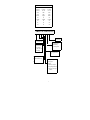
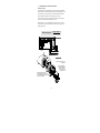
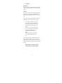
PSM INSTRUMENTATION LTD
SERIES 290/3000
DIFFERENTIAL PRESSURE
TRANSMITTERS
USER MANUAL
Models covered: 3660/DP, 3670/DP,
3675/DP, 290/DP, 292/DP & 295/DP
Issue 2 date 10th June ‘97
Burrell Road Industrial Estate
Haywards Heath, West Sussex RH16 1TW, UK
Tel: +44 (0)1444 410040 Fax: +44 (0)1444 410121
Http://www.psm-sensor.co.uk E-mail: [email protected]
1
INDEX
SECTION
TITLE
PAGE
1
Introduction
4
2
Specifications
5
6
Model coding
3
Transmitter Installation Mechanical
General arrangement Drawings
8
9
4
Transmitter Installation Electrical
10
5
Commissioning
11
11
Range & Zero adjustment
6
Fault Finding
12
3
1.
INTRODUCTION
Series 3000 and 290 differential pressure transmitters are intended for
applications across a wide range of processes from ultra low to medium
pressure duties.
Different constructions and materials are available to suit a particular duty
The measurement principle is based on a precision rated diaphragm
and linear variable differential transformer (LVDT) combination.
On all models the pressure chamber houses a rated pressure element
to which the process pressure is directly applied. Backing plates are
provided to protect against pressure overloads, and full asymmetric
protection is achieved on certain models by employing a
hydraulically linked dual diaphragm assembly,
The pressure element is attached to a ferro magnetic core which is located in
the centre (null point) of a high resolution linear variable differential
transformer(LVDT). When voltage is applied to the primary coil, any
movement of the core due to pressure on the measuring element develops a
voltage in the two secondary coils. The output signal from these two coils is
then conditioned within the transmitter electronics to provide a standard
process control signal output, which, using the adjustments provided, may be
set by the user to the process requirements.
4
2.
SPECIFICATIONS - General
Mechanical
Electronics Housing
Integral models:
Remote models:
Pressure housing:
Diaphragm material:
Remote sensor cable:
Process connections:
Electrical connections:
Integral models:
Remote models:
Electrical
Maximum error:
Stainless steel to IP65
GRP with internal RFI screen to IP65
316 St Stl
Hastelloy C, / St Stl.(model dependant)
Heavy duty TPE max length 100 metres
1/4” BSPT Fem on 54 mm centres
Standard DIN type connector.
PG9 Cable glands
Range adjustment:
Zero adjustment:
Signal output:
Power supply:
+/- 0.25% (including the effects of
non-linearity and hysteresis
30 to 100% of nominal input range
+/- 20 % of nominal input range
4 to 20 mA dc 2 wire
12 to 30 V dc
Performance
Operating temperature:
Temperature effect:
Humidity:
-25 to +80 deg C (+100 deg C remote)
Better than 0.05% per deg C
0-95 deg C RH non-condensing
Optional (remote versions only)
Square root extraction - non IS versions only
1
3 /2 digit LCD Indicator 0 to 100%
For Models, Input ranges, overload capabilities and arrangements see the
following tables:
5
Type
Nominal range: minimum
Nominal range : maximum
Maximum Static
Asymmetric Protection
Electronics
Intrinsic safety
Process connection
Centres on 54mm
Duty: Dry
Duty: Wet
Model coding
3660/DP
Differential
0 to 2 mb
0 to 10 mb
10 bar
5 bar
Integral
No
1/4" BSP
Yes
Yes
No
292/DP
Differential
0 to 2 mb
0 to 10mb
10 bar
5 bar
Remote
Yes
1/4" BSP
Yes
Yes
No
3670/DP
Differential
0 to 10 mb
0 to 50 mb
50 bar
20 bar
Integral
No
1/4" BSP
Yes
Yes
Yes
3675 / DP / 100mb / cont...
3660/DP - Ultra Low Diff.
Pressure
3670/DP - Low Diff. Pressure
3675/DP - Differential Pressure
290/DP - As 3670 but remote IS
Transmitter set range
S - Special calibration
2mb - Nominal range 2 mbar
5mb - Nominal range 5 mbar
10mb - Nominal range 10 mbar
20mb - nominal range 20 mbar
50mb - Nominal range 50 mbar
100mb - Nominal range 100 mbar
200mb - Nominal range 200 mbar
500mb - Nominal range 500 mbar
1b - Nominal range 1 bar
2b - Nominal range 2 bar
5b - Nominal range 5 bar
10b - Nominal range 10 bar
20b - Nominal range 20 bar
6
290/DP
Differential
0 to 10 mb
0 to 50 mb
50 bar
20 bar
Remote
Yes
1/4" BSP
Yes
No
Yes
3675/DP
Differential
0 to 50 mb
0 to 1 bar
50 bar
20 bar
Integral
No
1/4" BSP
Yes
Yes
Yes
295/DP
Differential
0 to 50 mb
0 to 1 bar
50 bar
20 bar
Remote
Yes
1/4" BSP
Yes
Yes
Yes
..75mb / 42 / 54 / XX/SR / 00 / WS / -
OX - Degreased
42 - 4 to 20 mA output
NB- No Bracket direct
manifold mounting
WS- 2” Standpipe/Wall
Process Connections
X - Non standard
54 - 54mm centres for
direct mounting
00 - Loop powered 24 V
DC
Specify cable length in Metres
(models 290/292/295 only)
P- -
NO - No options required
SR - Integral sq. rt.
extraction*
HC - Hastelloy wetted parts
DI - Integral digital indicator*
SD - Integral Sq. rt. & digital
indicator*
7
3.
TRANSMITTER INSTALLATION MECHANICAL
Pre installation checks
The Transmitter will normally have been manufactured, calibrated and tested in
accordance with the users specific requirements. It is recommended therefore,
that prior to commencing installation, the specification of the instrument as
supplied is checked to ensure that it is in accordance with actual installation
requirements. Checks should include nominal and actual ranges set, signal
output, power supply requirements and process connections. The relevant
information will be engraved on the label located on the transmitter body.
Transmitter Mounting
For integral units the transmitter may be either direct manifold mounted surface
mounted, or mounted on a standard 60mm instrument stand-pipe using the
optional mounting brackets. For remote models the sensor itself is generally
mounted directly to the pipework or 3 valve manifold, the remote amplifier
module is surface mounting only. In either case care should be taken to ensure
that the sensor is mounted level to within +/- 2 degrees. This especially
important for very low range models. Unless otherwise stated all transmitters
are calibrated in the level position.
System Piping
The size of the process connection to the pressure chamber will depend on what
was specified at the time of manufacture. The plastic protection plug, where
fitted, should be removed. Do not overtighten the pressure connection or insert
any objects through the entry hole since this may result in damage to the sensitive
pressure element.
In general it should be ensured that the pipework and valves used are compatible
with the process in terms of materials and pressure ratings. For liquid level
duties long pipe runs should have a gradient to assist in clearance and line size
1
should be /4" minimum. Where isolation valves are fitted they should be as
close to the transmitter as practical, ideally the transmitter should be directly
mounted to a 3 or 5 valve manifold.
For wet applications, to ensure that there is no air trapped in the system it will be
necessary to purge/bleed the sensor using the bleed screws provided.
On D.P. applications the pressure should first be equalised. This is especially
important on very low range units where asymmetric protection is limited.
8
193mm
GENERAL OUTLINE DRAWINGS
4 MOUNTING HOLES
ON 178 x 39mm
MODEL 3670
DETACHABLE
DIN PLUG
WALL MOUNTING
ELECTRONICS MODULE
ELECTRONICS
HOUSING
180mm
max
4 x 7/16 tapped
holes for
manifold/bracket
SENSOR
BODY
54mm
84mm
PG 9
CABLE
GLAND
SINTERED
BREATHER
CABLE LENGTH
AS REQUIRED
O38mm
2 x 1/4 BSP
female Process
connections
41.3mm
75mm
MODEL 290
Booted Cable
exit
SENSOR
BODY
75mm
54mm
84mm
75mm
75mm
75mm
193mm
4 MOUNTING HOLES
ON 178 x 39mm
MODEL 3675
DETACHABLE
DIN PLUG
WALL MOUNTING
ELECTRONICS MODULE
ELECTRONICS
HOUSING
180mm
max
4 x 7/16 tapped
holes for
manifold/bracket
SENSOR
BODY
54mm
84mm
PG 9
CABLE
GLAND
SINTERED
BREATHER
CABLE LENGTH
AS REQUIRED
O38mm
2 x 1/4 BSP
female Process
connections
41.3mm
75mm
MODEL 295
Booted Cable
exit
SENSOR
BODY
75mm
54mm
84mm
75mm
75mm
75mm
193mm
4 MOUNTING HOLES
ON 178 x 39mm
MODEL 3660
DETACHABLE
DIN PLUG
WALL MOUNTING
ELECTRONICS MODULE
ELECTRONICS
HOUSING
180mm
max
101.6mm
SENSOR
BODY
41.3mm
54mm
84mm
9
Booted Cable
exit
SENSOR
BODY
54mm
84mm
101.6mm
PG 9
CABLE
GLAND
SINTERED
BREATHER
CABLE LENGTH
AS REQUIRED
O38mm
2 x 1/4 BSP
female Process
connections
4 x 7/16 tapped
holes for
manifold/bracket
75mm
MODEL 292
101.6mm
101.6mm
4.
TRANSMITTER INSTALLATION ELECTRICAL
Electrical connections
On remote models the signal and supply cable is connected to the terminal block
via PG9 cable glands. On integral models an industry standard DIN plug is used
The cabling may be of screened, flexible or mineral insulated type dependant
upon the application requirements, maximum conductor size 1.5mm.
Prior to connection of any power supply it should be ensured that the voltage is
correct for the transmitter otherwise damage may result.
Where other devices are to be included in the signal loop for 2 wire 4 to 20mA
output transmitters, the total loop impedance may not exceed the figure given by
the following equation:-
Maximum output load =
Supply Voltage -12
0.002
RANGE
EX-
+ mAA
B
C
TEST POINTS
INDICATOR
EX+ OP+ OP-
Remote Models
- +
4 to 20mA
output
signal
ZERO
4 to 20 mA 2 Wire
Sensor
Connection
+
12 to 30 V dc
_
RANGE
GREEN
Ground
Z
Integral Models
BLACK
negative
2
R
Loosen securing screw A and
remove plug.
Ground
negative
2
ZERO
RED
positive
1
Terminal block may be
removed from the housing
positive
by carefully levering it out using 1
the slots provided.
It is recommended that
screened cable is used
and that the screen
is connected to the
ground terminal
A
10
5.
TRANSMITTER COMMISSIONING
Under normal circumstances the instrument will have been supplied with range
and zero controls preset according to the users specifications, therefore, no
adjustment should be necessary. However, it may be when the transmitter is
installed, trimming of zero and/or range settings are necessary. It may also be
that the transmitter is to be reset for a different application.
On integral models access to the zero and span adjustment potentiometers is
provided by undoing the plastic locking ring at the rear of the body.
On remote models the zero and span adjustments are located on the lower PCB
and accessed vis 2 holes in the upper PCB.
In both cases the potentiometers are clearly identified.
Where practical all adjustments should be made with the transmitter installed on
the process and the range and zero settings validated by measurement of the
output signal at 0 and 100% of the process pressure. Where it is not practical to
vary the process pressure to suit, an alternative pressure source may be
employed, this should be an high
accuracy device such as an air driven dead weight tester, laboratory digital
pressure standard, water or mercury column.
Range & Zero adjustments
The zero should be adjusted firstly, the instrument is of the 'live zero' type
therefore for when no pressure is applied the output signal should be 4.00mA .
Once this is achieved the range potentiometer should be adjusted with the
required max. pressure applied to the instrument until the output signal is 20mA.
It is recommended that the zero be rechecked after range adjustment
.
Display scaling Remote models - optional digital indicator
Note:
DIL Sw 1 & DIL Sw. 2 should not be in the on position at
the same time. Display scaling should be performed after any
range and zero adjustments are made.
1
Where the optional 3 /2 digit display is fitted an additional board is housed in the
amplifier module. Two DIL switches 1 & 2, plus a zero and a range
potentiometer are included.. scaling of the digital indicator is performed using
these controls. With zero pressure applied the left hand potentiometer should be
adjusted until the display reads zero, and when full scale pressure is applied, the
right hand potentiometer should be adjusted until the meter reads as required.
Placement of the decimal point may be altered using DIL switches marked 1. and
2. as follows:With both off max. full scale value is :
1999
With DIL sw.2. on max. full scale value is : 199.9
With DIL sw.1. on max full scale value is: 19.99
11
6.
FAULT FINDING
Routine Maintenance
The design of these transmitters is such that no routine maintenance is required
except for periodic examination of gaskets and security of pressure and electrical
connections
Fault Finding
These transmitters are sensitive and accurate measuring instruments and have no
mechanical wearing or contacting parts. If installation procedures have been
followed correctly the instrument should give satisfactory operation over a long
period.
In cases of failure or poor operation following installation or in normal service
the following check list may assist in isolating the cause of any problems.
1
2
3
4
5
6
7
Are the range details of the transmitter correct for the duty?
Fully check impulse piping and wiring installation, have any
leaks developed or are there any poor electrical connections?
Is the transmitter isolation valve (if fitted) fully in the open
position?
Is there pressure in the process and is it of the correct order?
Is the correct power supply applied to the transmitter and is it
actually present at the transmitter terminals?
Check the output from the transmitter at the receiving
instrument.
If all the foregoing are found to be in order then it will be
necessary to isolate the instrument and remove it from
process.
Check that no sludge or foreign matter has collected in the transmitter pressure
chamber. Any deposits can normally be seen clearly at the entrance to the
pressure housing. Do not use any tools or other pointed objects to clean inside
the chamber, this should only be done flushing with solvents suitable for use with
nitrile rubber.
Should the problems persist consult PSM Service department
on 01444 410040 or return to the factory for examination.
12