1
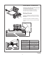
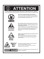
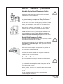
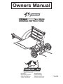
Owners Manual
ORIGINAL INSTRUCTIONS
Head Office:
P.O. Box 2018
Hilton Highway, Washdyke
Timaru, New Zealand
Telephone (03) 688 2029
Facsimile (03) 688 2821
Australian Branch:
4B Silverton Close
Laverton North 3026
Melbourne, Australia
Telephone (03) 9314-9666
Facsimile (03) 9314-6810
Pt. No. 67368
Issue 0510
Duncan SLR Feeder
Contents
Page
Introduction
Acquisition & Warranty
Disclaimer
Description of Machine
Specification
......................................
2
......................................
2
......................................
2
Working Principle. . . . . . . . . . . . . . . . . . . . . . .
3
......................................
3
SAFETY - General
Safety Symbols on Machine . . . . . . . . . . . . . .
Operator Safety . . . . . . . . . . . . . . . . . . . . . . . .
Be Prepared for Emergencies . . . . . . . . . . . . .
Appropriate Dress . . . . . . . . . . . . . . . . . . . . . .
Transport This Machine Safely . . . . . . . . . . . .
Handle Agricultural Chemicals Safely . . . . . . .
Avoid High Pressure Fluids . . . . . . . . . . . . . . .
Safe Work Practices . . . . . . . . . . . . . . . . . . . .
Practise Safe Maintenance . . . . . . . . . . . . . . .
Hazard Points . . . . . . . . . . . . . . . . . . . . . . . . .
Safety Decals & Safety Guards. . . . . . . . . . . .
......................................
4
5
5
6
6
7
7
7
8
9
11
12
Operation
Tractor hookup . . . . . . . . . . . . . . . . . . . . . . . .
Loading a bale. . . . . . . . . . . . . . . . . . . . . . . . .
Feeding out . . . . . . . . . . . . . . . . . . . . . . . . . . .
13
14
15
Maintenance & Care
Lubrication Instructions . . . . . . . . . . . . . . . . . .
Maintenance Schedule . . . . . . . . . . . . . . . . . .
Storage . . . . . . . . . . . . . . . . . . . . . . . . . . . . . .
Maintenance Notes . . . . . . . . . . . . . . . . . . . . .
16
17
17
18
Parts List
Base Machine . . . . . . . . . . . . . . . . . . . . . . . . .
Main Assembly . . . . . . . . . . . . . . . . . . . . . . . .
Machine Base . . . . . . . . . . . . . . . . . . . . . . . . .
Forks System. . . . . . . . . . . . . . . . . . . . . . . . . .
Bed System Drive . . . . . . . . . . . . . . . . . . . . . .
Bed System Extension, Wear Strip, Ram Pin .
Hydraulics . . . . . . . . . . . . . . . . . . . . . . . . . . . .
21
22
24
26
28
30
32
SAFETY - Machine Specific
Transport
Pt. No. 67368
Issue 0510
1
Introduction
Acquisition & Warranty
On delivery of your new Duncan SLR Feeder please check
that the machine is not damaged. In cases of shipping
damage, please ask your dealer to arrange for the appropriate
claim to be lodged immediately. Assemble any parts supplied
loose and inspect your machine with the aid of this manual to
familiarise yourself with its features. If you have any queries
ask your dealer straight away. The machine is covered by our
12 month warranty on faulty parts, subject to normal use.
Record the serial number of your machine below and keep
it in a secure place to help trace the machine and assist
us when you order parts.
Model: . . . . . . . . . . . . . . . . . . . . . . . . . . . . . . . . . . . . . .
Serial No: . . . . . . . . . . . . . . . . . . . . . . . . . . . . . . . . . . .
Owner:. . . . . . . . . . . . . . . . . . . . . . . . . . . . . . . . . . . . . .
.............................................
.............................................
Delivery Date:. . . . . . . . . . . . . . . . . . . . . . . . . . . . . . .
Dealer: . . . . . . . . . . . . . . . . . . . . . . . . . . . . . . . . . . . . . .
.............................................
.............................................
The Owner’s Manual
Your new Duncan SLR Feeder will give long and efficient
service if given normal care and operated properly.
This owner’s manual is provided so that you can become
thoroughly familiar with the design of the machine and to
furnish information on correct operation, adjustment and
maintenance. Only persons well acquainted with these
guidelines should be allowed to use the equipment.
A separate illustrated parts section has been provided so that
if any parts are required your dealer will be able to supply
them by reference to part numbers.
The manual is considered as part of your machine and must
remain with the machine when it is sold.
Right and left hand references in this manual are
determined by standing behind the machine and facing in
the direction of travel.
2
This Document contains the Original
Operating Instructions for this machine
and are verified by the Manufacturer.
Signed:......................................
Product Development Manager
Disclaimer
Every effort has been made to
ensure that the information in this
manual was accurate and up to
date at the time of going to press.
Clough Agriculture Ltd reserves the
right to make subsequent changes
to the machine, where necessary,
without notification.
The Company will not be
responsible for any damage or
consequential loss arising out of
misinterpretation or failure to follow
recommended procedures. Nor will
it be liable for any damage caused
by or arising out of modification or
misuse of its product.
The owner has a responsibility
to protect himself and others
by observing all safety
information and by ensuring all
operators are well acquainted
with the safety information,
trained in the correct use of
the machine and applying safe
work practices.
Description of Machine
The Duncan ‘SLR Feeder’ will handle Square bales,
Loose silage and Round bales.
The fork and bed system give the user full control
over loading and unwrapping of the bale.
Two bales may be carried on the machine.
Working Principle
The bale is loaded by reversing into it and then
placing it on the feedout bed using the hydraulic
fork system.
The bale may be held to facilitate unwrapping.
The bale may then be fed out under full operator
control.
1572
2250
4105
4485
4635
5475
Specifications
Max Bale Size Round
6 ft
Max Bale Size Square
6ft x 6ft (x 8ft Long)
Tyre Size/Load Rating
10/75 15.3 10 Ply (123A8)
Tyre Pressure
2215
2500
2910
5.2 bar (75psi)
Unladen Weight
1275kg
Drawbar Weight
420kg
Maximum Speed
40km/hr
Pt. No. 67368
Issue 0510
3
!
ATTENTION
On the machine important safety information is indicated by these symbols.
These highlight general safety aspects in regard to the machine rather than specific hazards.
Do not ride or allow passengers on the machine.
Under no circumstances are passengers to be permitted
on the machine while it is in operation or being transported.
Any footboards and/or footsteps are provided solely for the
purpose of preparing the machine for use.
Keep clothing and body extremities well clear of pinch
points while the machine is operating Keep well clear of
moving parts at all times.
These signs typically occur wherever trapping points exist.
These include drive chains, sprockets, shafts, wheels, pivot
points, etc. Guards are provided with the machine for safety
reasons (where practical without compromising machine
performance). Ensure these are always fitted during
operation.
Always exercise extreme caution in the vicinity of sharp
edges and points.
Where possible guards are provided with the machine
for safety reasons (where practical without compromising
machine performance). Ensure these are always fitted
during operation.
Footboards, footsteps, drawbars and other machine
surfaces may be slippery when wet.
Apply extra caution in wet conditions and in the early
morning when surfaces are wet.
Keep Clear. (It is dangerous to be in this area when the
machine is operating.)
4
SAFETY - General
N.B. Throughout this
manual important safety
information is indicated
by these symbols in the
margin:
A prohibition should
be observed under all
circumstances.
A warning indicates a
hazard that could cause
death or injury if the
warning is ignored.
A caution indicates a
hazard that may cause
damage to property if
the caution is ignored.
This section of the manual offers general guidelines
for the safe operation of machinery. It does not replace
local safety regulations. These guidelines were current at
the time of publication, but may be superseded by later
regulations.
Clough Agriculture has made every effort to highlight all
risks to personnel or property. Owners and operators have
a responsibility to exercise care and safe work practices at
all times in the vicinity of the machine.
Owners are advised to keep up to date on safety issues
and to communicate these to all users of the machine.
Contact the Occupational Safety and Health Service
(OSH) for further information about general safety aspects.
If you have safety concerns specifically related to this
machine, contact your dealer immediately.
Operator Safety
Read this manual carefully before operating new
equipment. Learn how to use this machine safely.
Be thoroughly familiar with the controls and the proper use
of the equipment before using it.
Take careful note of all safety instructions both in this
manual and on the machine itself. Failure to comply with
instructions could result in personal injury and/or damage
to the machine.
Replace missing or damaged safety signs on the machine
and ensure that these remain clearly visible.
It is the owner’s responsibility to ensure that anyone
who operates, adjusts, lubricates, maintains, cleans
or uses the machine in any way has had suitable
instruction and is familiar with the information in this
manual (particularly with regard to safety aspects).
Operators and other users of the machine should be
aware of potential hazards and operating limitations.
Be Prepared for Emergencies
Keep a first aid kit and fire extinguisher handy.
Keep emergency numbers for doctors, ambulance,
hospital and fire department near your telephone.
Pt. No. 67368
Issue 0510
5
SAFETY - General (Continued)
Appropriate Dress
Wear close fitting clothing and avoid rings or other forms of
jewellery which could become caught in the machinery.
People with long hair must have it securely fixed and confined
close to the head.
Refer to local safety standards for protective clothing and
recommended safety equipment.
Adequate protection, such as a face mask, should be worn if
operating this machine in dry and dusty conditions.
Transport This Machine Safely
Ensure that all linkage pins and security clips are fitted correctly.
With trailing machines tow with the drawbar only, as this is the
only safe towing point on the machine.
Always check that bystanders (especially children) are well clear
(front and rear) before starting and moving the tractor and the
machine.
Plan safe routes of travel, and be aware of power lines and
other roadside hazards. Take particular care when towing
implements on hillsides.
Do not ride or allow passengers on the machine.
This machine is not designed to carry passengers, and no riders
are permitted.
Road transport
On public roads,
• A speed of 40km/h must not be exceeded.
• Do not operate during the hours of darkness unless standard
lights are fitted and clearly visible. (This also applies when
visibility is limited, e.g., in foggy conditions.)
See the guidelines in the Vehicle Dimensions and Mass Rule,
issued by the Land & Transport Safety Authority.
Avoid tip-overs
Run the machine along hillsides with the elevator on the high side
of the hill. Avoid holes, ditches and obstructions which may cause
the machine to tip over, especially on hillsides. Never drive near
the edge of a gully or steep embankment - it might cave in. Slow
down for hillsides, rough ground and sharp turns.
6
SAFETY - General (Continued)
Handle Agricultural Chemicals Safely
All farm chemicals should be stored, used, handled and
disposed of safely and in accordance with the supplier’s/
manufacturer’s recommendations.
Read the product label before using, noting any warnings
or special cautions, including any protective clothing or
equipment that may be required, ie. respirator.
Do not eat or smoke while handling sprays, fertilisers, coated
seeds, etc. Afterwards, always wash your hands and face
before you eat, drink, smoke, or use the toilet.
Store sprays, fertilisers, coated seeds, etc. out of reach of
children and pets, and away from food and animal feeds.
Any symptoms of illness during or after using chemicals
should be treated according to the supplier’s/manufacturer’s
recommendations. If severe, call a physician or get the
patient to hospital immediately. Keep the container and/or
label for reference.
Avoid High Pressure Fluids
Avoid any contact with fluids leaking under pressure, because
the fluids can penetrate the skin surface.
Any fluid which penetrates the skin, will need to be removed
immediately by a medical expert. Seek specialist advice on
this type of injury.
Relieve the pressure before disconnecting any hydraulic or
other lines. Make all repairs and tighten all fittings before
re-connection to pressurised fluid.
Keep your hands and body away from any pinholes or high
pressure jets. Search for leaks with a piece of cardboard
instead of using your hand directly.
Safe Work Practices
All farm machinery is potentially dangerous and should be
treated with caution and respect.
Before starting the machine, ensure that all controls are placed
in neutral and that bystanders are well clear. Check that the
guards have been securely fitted and that any adjustments
have been made correctly.
Where possible, disconnect or isolate the drive mechanism to
the implement. Lower the machine onto the ground when not
in use.
Do not operate this equipment when severe weather
conditions appear imminent.
Pt. No. 67368
Issue 0510
7
SAFETY - General (Continued)
Practice Safe Maintenance
Keep the machine in safe working condition. Routine maintenance
and regular servicing will help reduce risks and prolong the life of the
machine.
General Maintenance
Accidents occur most frequently during servicing and repair. The
following general rules must be followed when maintaining or working
with machinery:
• All operating and maintenance manuals must be
read before and referred to while using or servicing any
piece ofequipment.
• Turn off all machinery power sources and isolate the
machine before making adjustments, doing lubrication,
repairs or any other maintenance on the machine.
• Ensure that the machine hydraulics are disconnected from
the power source.
• Wear gloves when handling components with cutting
edges, such as any ground cutting components.
• Beware of hazards created by springs under tension
or compression when dismantling or maintaining the
machine.
• It is recommended that you clean the machine with a water
blaster or similar apparatus before commencing
maintenance.
Make Sure the Machine is Well Supported
When machinery is fitted with hydraulics, do not rely on the
hydraulics to support the machine. During maintenance or while
making adjustments under the machine, always lock the hydraulics
and support the machine securely. Place blocks or other stable
supports under elevated parts before working on these.
Electrical Maintenance
Disconnect the electrical supply from the tractor before doing any
electrical maintenance.
Welding
With electronic equipment in modern tractors it is advisable to disconnect
the machine from the tractor, or at least disconnect the alternator and
battery before attempting any welding.
Use Only Genuine Spare Parts
Unauthorised modifications or non-genuine spare parts may be
hazardous and impair the safe operation and working life of the machine.
Excess lubricants must be disposed of safely so as not to become a
hazard.
8
SAFETY - Machine Specific
This section of the manual gives specific guidelines for
the safe operation of the SLR Feeder.
These guidelines were current at the time of publication, but
may be superseded by later circumstances. They do not
necessarily cover every possible hazard and must be read in
conjunction with the SAFETY - General section (Page 4 - 8).
Hazard Points on the SLR Feeder
The lists below are not all-inclusive and serve only to highlight
the more obvious areas of risk.
The decals attached to the machine are a general reminder
that there are hazardous areas on the machine, rather than
specifically highlighting all possible hazards.
For decal locations on machine, refer Page 11.
No Ride
Passengers are not permitted anywhere on the machine.
Pinch Points/Moving Parts
Hazardous areas include:
• Elevator chains and sprockets.
• Hydraulic motor and torque arm.
• Loading arm.
• Fork loading system.
• Feedout bed.
• Hydraulic cylinders on the bed, frame and fork system.
Slippery When Wet
Hazardous areas include:
• Feedout Bed
• All smooth surfaces on the frame structure.
Keep Clear
Hazardous areas include:
• Between the tractor and SLR Feeder.
• Immediately adjacent to the SLR Feeder chain side.
Pt. No. 67368
Issue 0510
9
10
SAFETY - Machine Specific (Continued)
Safety Decals
5
1
2
1
2
2
4
4
4
5
6
5
3
3
2
1
2
7
4
Item Decal/Guard
2
Cross Ref.
Pt. No. Qty
1
‘No Ride’
Refer Page 9
43900
3
2
‘Pinch Point/Moving Parts’
Refer Page 9
43901
5
3
‘Slippery When Wet’
Refer Page 9
43902
2
4
‘Keep Clear’
Refer Page 9
43904
2
5
‘40 km/hr’
-
43912
2
6
Duncan Bull
-
61525
2
7
Duncan SLR Feeder
-
61524
1
Pt. No. 67368
Issue 0510
11
Road Transport
1
Raise the Bale Forks into the transport position.
2
Locate jack stand in transport position.
3
Ensure lighting and oversize warning requirements meet
recommendations published by the local Land Transport
Authority or equivalent. The Feedout Bed extension is
removable if required.
4
Maximum towing speed 40 km/hr.
For countries other than New Zealand different speed
restrictions may apply, please refer to your local
transport authority.
Ensure towing vehicle requirements are adequate
for the towed vehicle e.g. mass, brakes. Refer to
recommendations published by the local Land Transport
Authority or equivalent.
Braking when towing can cause the load to jackknife. Use
extra care when towing in adverse conditions such as mud,
inclines and sharp bends.
Lower towing speeds are recommmended on farm roads/
tracks and where one wheel is on or over a road verge.
5
Attach safety chains to tractor.
Safety chains must be crossed over underneath the
coupling and attached to the towing vehicle. The
attachment points must be as close as practical to the
towing coupling and one each side.The towbar on the
towing vehicle must be rated for the towed mass. Do not
remove or replace the safety chains provided with any
other than those specified in the parts manual.
Note: The safety chains are provided with sufficient
length to cater for all towing vehicles. Safety chains must
be shortened by cutting off excess length so that if the
coupling fails the drawbar will not hit the ground.
1
5
2
12
Operation
Attaching machine to tractor
1. Use the jackstand to align the hitch point with the tractor
For correct operation, the machine should be parallel
to the ground. The machine coupling may be adjusted
to accomodate different tractior drawbar heights.
2. Reverse the tractor into position and locate the hitch pin
into the drawbar ensuring that the safety linch pin is in
place.This is to prevent the machine from accidentaly
detaching from the tractor.
3. Locate the jackstand in the transport position.
4.
Warning: Attach safety chains between tractor and
the machine. Safety chains will help to control drawn
equipment should it accidentally separate from the drawbar
whilst in transport or operation.
5. Place the hydraulic hoses into the correct tractor outlets.
Ensure that all moving parts of the machine are free from
obstacles and run and check the functions of the machine.
Warning: Ensure people and animals are at a safe
distance away from the moving parts before running the
machine.
Detaching Machine from Tractor
1. Reverse the machine into your storage area. Where
possible, retract all hydraulic rams.
2. Turn the jackstand to the vertical postion and lock in place.
Take the load off the drawbar and remove hitch pin and
safety chains as required.
3. Release pressure and dissconnect hydraulic hoses, close
tractor outlet covers and install dust covers over the hose
ends.
Pt. No. 67368
Issue 0510
13
Loading a Bale
1. Lower rear forks to their lowest position
refering to the position indiactor on the top
of the drawbar as a guide. For larger bales,
the forks may be raised slightly as required.
2. Reverse to spear the bale all the way.
3. Lift the bale and bring to the desired
position for unwrapping. For looser bales,
cut the strings/unwrap with the bale closer
to the bed to prevent the bale from falling
apart. A loop is provided under the bed
extension to tie the cut string to if the bale
is sitting on the original knots and cannot be
pulled free. Tying the strings to the machine
will prevent the strings from getting wrapped
around the elevator chain.
4. Lower the bale onto the feedout bed.
5. The forks will retract and reset to the
loading position.
6. If required, a second bale may be loaded
and held with the lift arm close to vertical.
Use the postion indicator (see below) on the
drawbar as a guide if the arm is obscured
by the previously loaded bale.
Bed clear
of fork arm
Ready to
pickup bale
14
Feeding Out
1. Ensure that all plastic wrapping, mesh and loose string has been removed.
2. If a second bale is on the forks, ensure that the forks are in the correct positon to allow the bed
to tilt and feedout. Look at the fork position indicator on the drawbar and move the forks back if
required. (See previous page)
3. The bed may be tilted when feeding out to alter the delivery. The elevator chain tines are
aggresive enough to tear the bale.
4. Round bales rotate and unwrap depending on the original bale winding direction. If too much
is being fed out, tilt the bed back to allow the chains to create a flat on the bale; that will stop it
from rotating and unwinding too much.
5. Experiment with the machine and note the different effects depending on which way round the
bale was loaded and the various types and ages of feed.
6. If the elevator chain speed is too fast or too slow, you may need to alter the flow control on the
tractor remotes.
7. When feeding out on hillsides, keep the elevator on the high side of the hill; this reduces the risk
of roll-over and gives better control of the bale.
Pt. No. 67368
Issue 0510
15
Maintenance & Care - Lubrication Instructions
Precautions with Grease
Greases should not be mixed as the structure may be weakened by the
mixes of different types of thickener, which may cause softening and loss of
grease from the bearings by running out.
Your new Duncan SLR Feeder
will give long and efficient
service if given normal care and
maintained properly.
4
3
3
2
2
Bed Lift Ram -Grease Nipple both ends
6 Main 4” Lift Ram -Rod End Nipple
Fork Tilt Ram -Rod End Nipple
5
1
5
Lubrication Chart
Item
*
Components
Lubricant
Frequency
1
Wheel Bearings
Castrol LMX Grease
Annually
2
Bed Pivot Bearings
Castrol LMX Grease
6 Monthly
3
Elevator Chain Bearings Castrol LMX Grease
Every Month
4
Elevator Chain
Suitable Roller Chain Lubricant
6 Monthly
5
Pivot Pins
Castrol LMX Grease
Weekly
6
Cylinder Pivots
Castrol LMX Grease
Weekly
The lubrication frequencies are only a guide. Actual frequency will be dependent on extent of use and ground conditions.
Pt. No. 67368
Issue 0510
16
Maintenance & Care - Lubrication Instructions
Precautions with Grease
Greases should not be mixed as the structure may be weakened by the
mixes of different types of thickener, which may cause softening and loss of
grease from the bearings by running out.
Weekly
Monthly
Pre Season
Wheel Nuts
●
●
●
Ram & Pivot Pin Fasteners
●
●
●
Coupling & Safety Chains
●
●
●
Y Bearings
●
●
Roller Chains
●
●
Hydraulics (Oil Leaks)
●
●
Tyre Pressures (see page 3)
●
●
●
●
Components
Bolted Connections
●
Mechanical Adjustments
Elevator Chain Tension Settings
1. Check the elevator chain tension after the
1st month of operation, and therafter monthly
depending on use.
2. To adjust the elevator chain tension first disconnect
all hydraulic hoses from the tractor. Loosen the
tension bolts and, using a pry bar, set the tensioner
blocks against the chain to the dimension shown.
WARNING: The tine points are sharp and at eye
level.
Storage
Before storage, water blast the machine and
remove mud and excess feed which may have
accumulated during the season. Check that the
elevator chain shaft is not wrapped with material.
Elevator chains should have an excess of oil
applied to them. Run the machine and repeat this
operation to ensure the chains are well lubricated
and any contaminants have been flushed out.
Remove excess oil from the bed. Lubricant can be
clean used hydraulic oil or transmission oil.
The machine should be stored with the rams
retracted to ensure the rods are protected.
17
160mm
SLR Feeder
18
Maintenance Notes
Pt. No. 67368
Issue 0510
19
20
Parts List
‘SLR Feeder’
Head Office:
P.O. Box 2018
Hilton Highway, Washdyke
Timaru, New Zealand
Telephone (03) 688 2029
Facsimile (03) 688 2821
Australian Branch:
4B Silverton Close
Laverton North 3026
Melbourne, Australia
Telephone (03) 9314-9666
Facsimile (03) 9314-6810
Pt. No. 67368
Issue 0510
21
‘SLR Feeder’
Assembly
3
4
5
2
1
6
7
8
9
22
‘SLR Feeder’
Assembly
ITEM
PART No.
DESCRIPTION
QTY
1
Refer Page 24-25
Machine Base
1
2
Refer Page 26-27
Forks System
1
3
Refer Page 28-31
Bed System
1
4
45140
M16 Nyloc Nut
8
5
45040
M16 X 50 8.8 Z/P Bolt
8
6
61337
Pivot Pin Forks System
1
7
45020
M12 x 35 8.8 Z/P Bolt
1
8
45167
M12 Spring Washer
1
9
45159
M12 HD Flat Washer
1
For clarity, hydraulic rams are shown on the ‘Machine Base’, ‘Forks System’ and ‘Bed System’
pages respectively
Pt. No. 67368
Issue 0510
23
‘SLR Feeder’
7
6
Machine Base
2
27
28
1
5
4
3
9 11
12
13
3
14
9
23
24
10
25
8
26
18
19
17
15
16
24
20 21
22
‘SLR Feeder’
DESCRIPTION
Machine Base
ITEM
PART No.
QTY
1
61343
Chassis Welded Assembly
1
2
61355
Hydraulic Cylinder 3” x 1.5” x 375mm Stroke
1
3
43118
Straight Grease Nipple M8
2
4
61336
Pivot Pin
1
5
45159
M12 HD Flat Washer
2
6
45167
M12 Spring Washer
2
7
45018s
M12 x 25 8.8 Z/P Setscrew
1
8
31478
Jackstand 2500kg
1
9
43660
Double Tube Clamp
3
10
44965
M8 x 45 8.8 Bolt Z/P (Spares only)
1
11
45677
M8 x 80 8.8 Bolt Z/P (Spares only)
1
12
4800315
Hose Support
1
13
45181
M8 x 12 S/H Grub Screw
1
14
61516
Indicator Rod Welded Assembly
1
15
61315
Drawbar Hitch
1
16
43830
Safety Chain No.2
2
17
45078
M20 x 180 8.8 Z/P Bolt
3
18
45141
M20 Nyloc Nut
3
19
61522
Spacer
1
20
61323
Hub with bearings- 6 Stud 50mm
2
21
Call
Hub Rebuild Kit
1
22
45639
Wheel Assembly 10.0/75-15.3 6 Stud 10 Ply
2
23
61356
Hydraulic Cylinder 4” x 2.5” x 355mm Stroke
1
24
61335
Ram Base Pin
1
25
45168
M16 Spring Washer
2
26
45037s
M16 x 35 8.8 Setscrew
2
27
45152
M10 Light Flat Washer
1
28
45271
R Clip
1
Pt. No. 67368
Issue 0510
25
‘SLR Feeder’
2
Forks System
16
15
8
12
9
11
14
15
9
16
7
12
5
11
16
3
6
10
11
12
12
11
10
1
11
5
4
26
12
10
13
‘SLR Feeder’
DESCRIPTION
Forks System
ITEM
PART No.
QTY
1
61384
Forks Frame Welded Assembly
1
2
61320
Forks Lift Arm Welded Assembly
1
3
61357
Hydraulic Cylinder 3” x 1.5” x 270mm Stroke
1
4
43169
Bale Tine Conus II 980mm Long with Nut
2
5
61340
Forks Pivot Pin
2
6
61336
Fork Ram Pin
1
7
61338
Main Ram Pin
1
8
61339
Fork Ram Base Pin
1
9
43426
Glacier Bush
6
10
45019s
M12 x 30 8.8 Setscrew Z/P
3
11
45167
M12 Spring Washer
5
12
45159
M12 HD Flat Washer
5
13
45022
M12 x 45 8.8 Bolt Z/P
1
14
45021
M12 x 40 8.8 Bolt Z/P
1
15
61436
Tab Anchor Spacer
2
16
43118
Straight Grease Nipple M8
4
Pt. No. 67368
Issue 0510
27
‘SLR Feeder’
8
7
14
2
9
Bed System Drive
13
12
10
15
11
3
9
2
22
4
Non-drive Side
5
Drive Side
5
6
1
20
21
10
16
2
19
17
10
11
28
18
‘SLR Feeder’
DESCRIPTION
Bed System Drive
ITEM
PART No.
QTY
1
61327
Bed/Elevator Welded Assembly
1
2
43986
Y Bearing
4
3
30444
Hydraulic Motor 2 Bolt
1
4
61398
Motor Mount/Torque Arm Assembly
1
5
61397
Top Shaft Welded Assembly
1
6
61395
Chain Welded Assembly
1
7
61500
Shroud – Drive Side
1
8
61504
Shroud – Non-drive Side
1
9
45039
M16 x 45 8.8 Bolt Z/P
8
10
45154
M16 Light Flat Washer
16
11
45140
M16 Nyloc Nut
12
12
45419
M10 x 30 8.8 Bolt Z/P
1
13
45158
M10 HD Flat Washer
1
14
45138
M10 Nyloc Nut
1
15
45139
M12 Nyloc Nut
2
16
61396
Tensioner Mount
2
17
34082
Chain Rubbing Block
2
18
45911
M6 x 30 Pan Pozi Screw Z/P
4
19
45136
M6 Nyloc Nut
4
20
45132
M16 Nut 8.8 Z/P
8
21
45043s
M16 x 65 8.8 Setscrew Z/P
4
22
30433
Key 1/4” x 1” Woodruff No. 808
1
Pt. No. 67368
Issue 0510
29
‘SLR Feeder’
4
1
3
2
8
7
6
5
3
11
10
9
30
Bed System
‘SLR Feeder’
Bed System
ITEM
PART No.
DESCRIPTION
QTY
1
61318
Bed Extension
1
2
45027
M12 x 70 8.8 Bolt Z/P
4
3
45159
M12 HD Flat Washer
5
4
45139
M12 Nyloc Nut
4
5
61496
Floor Wearstrip
1
6
44965
M8 x 45 8.8 Bolt Z/P
3
7
45157
M8 HD Flat Washer
6
8
45137
M8 Nyloc Nut
3
9
61336
Bed Ram Pin
1
10
45018s
M12 x 25 8.8 Setscrew Z/P
1
11
45167
M12 Spring Washer
1
Pt. No. 67368
Issue 0510
31
‘SLR Feeder’
6 hose Hydraulics
Bed Tilt hydraulics (all versions)
6
head
1
3
8
9
< to tractor
8
2
9
10
base
Elevator Motor hydraulics (6 hose version only)
4
7
8
8
5
< to tractor
32
‘SLR Feeder’
ITEM
PART No.
DESCRIPTION
Hydraulics
QTY
Bed Tilt Hydraulics
1
61355
Bed Tilt Ram (see Page 30)
1
2
61530
Hydraulic Hose 4.50m long (Colour Code Yellow)
1
3
61531
Hydraulic Hose 4.62m long (Colour Code Yellow)
1
Elevator Motor Hydraulics
4
30444
Hydraulic Motor 2 bolt
1
5
61532
Hydraulic Hose 5.00m long (Colour Code Red)
2
6
43280
Nipple 3/4” UN'O to 3/8” BSPP
1
7
43035
Nipple 7/8” UN'O to 3/8” BSPP
2
8
43147
1/2” BSP Male Quick Release Coupling
4
9
43617
Dust Cover
4
10
45634
Flow Reducing Nipple 3/4” UN'O to 3/8” BSPP
1
Fittings
Pt. No. 67368
Issue 0510
33
‘SLR Feeder’
6 hose Hydraulics
Fork Tilt & Main Arm Ram & Sequence Valve (6 Hose versions)
1
9
10 11
12
13
8
B
< to tractor
A
12
13
2
7
3
9
B2
A2
6
9
A1
B1
8
9
5
10 11
4
7
14
15
16
34
‘SLR Feeder’
ITEM
PART No.
DESCRIPTION
Hydraulics
QTY
Fork Tilt Hydraulics
1
61357
Fork Tilt Ram (See Page 26)
1
2
61533
Hydraulic Hose 1.44m long
1
3
61534
Hydraulic Hose 1.80m long
1
Main Arm Hydraulics
4
61356
Main Arm Ram (See Page 24)
1
5
61535
Hydraulic Hose 0.45m long
1
6
61536
Hydraulic Hose 0.90m long
1
Valve & Fittings
7
61527
Sequencing Valve
1
8
61537
Hydraulic Hose 3.93m long (Colour Code Blue)
2
9
43280
Nipple 3/4” UN'O to 3/8” BSPP
4
10
43391
Dowty Washer
6
11
43392
Nipple 3/8”-3/8” BSPP
6
12
43147
1/2” BSP Male Quick Release Coupling
2
13
43617
Dust Cover
2
14
45151
M8 Light Flat Washer
4
15
45165
M8 Spring Washer
4
16
44993S
M8 x 25 8.8 Setscrew Z/P
4
Pt. No. 67368
Issue 0510
35
‘SLR Feeder’
7
4 Hose Hydraulics
Fork Tilt, Main Arm Ram ,Sequence Valve
and Diverter Valve (4 Hose versions)
1
17
16
8
15
A
20
21
All hose connections
to valves
F
D
C
B
18
2
19
3
16
E
B2
A2
B
13
16
A1
B1
A
14
6
12
5
4
16
Bed Tilt hydraulics (all versions)
16
head
9
10
20 21
< to tractor
11
20 21
36
22
base
‘SLR Feeder’
ITEM
PART No.
DESCRIPTION
Hydraulics
QTY
Fork Tilt Hydraulics
1
61357
Fork Tilt Ram (See Page 26)
1
2
61533
Hydraulic Hose 1.44m long
1
3
61534
Hydraulic Hose 1.80m long
1
Main Arm Hydraulics
4
61356
Main Arm Ram (See Page 24)
1
5
61535
Hydraulic Hose 0.45m long
1
6
61536
Hydraulic Hose 0.90m long
1
Elevator Motor Hydraulics
7
30444
Hydraulic Motor 2 bolt
1
8
61542
Hydraulic Hose 2.04m long to Diverter Valve
2
Bed Tilt Hydraulics
9
61355
Bed Tilt Ram (see Page 30)
1
10
61530
Hydraulic Hose 4.50m long (Colour Code Yellow)
1
11
61531
Hydraulic Hose 4.62m long (Colour Code Yellow)
1
Valves & Fittings
12
61527
Sequencing Valve
1
13
61541
Hydraulic Hose 0.55m long
2
14
61528
Diverter Valve
1
15
61537
Hydraulic Hose 3.93m long (Colour Code Blue)
2
16
43280
Nipple 3/4” UN'O to 3/8” BSPP
5
17
43035
Nipple 7/8” UN'O to 3/8” BSPP
2
18
43391
Dowty Washer
12
19
43392
Nipple 3/8”-3/8” BSPP
12
20
43147
1/2” BSP Male Quick Release Coupling
4
21
43617
Dust Cover
4
22
45634
Flow Reducing Nipple 3/4” UN'O to 3/8” BSPP
1
Refer to page 34 for Sequencing Valve fasteners.
Pt. No. 67368
Issue 0510
37
‘SLR Feeder’
6 Hose to 4 hose conversion kit
Diverter Valve kit to convert 6 Hose to 4 Hose
1
4
9
All hose connections
to diverter valve
5
6
F
D
A
C
B
E
B
A
2
7
B2
A2
A1
B1
3
8
Note: The hoses (item 3) between the diverter valve and
sequence valve are connected so that the normal (feed out)
rotation of the hydraulic motor and the lowering of the forks
is made by the same tractor control in the same direction.
This is so that if the bed is lowered when the hydraulic
motor is running the fork arm will move away from the bed.
38
‘SLR Feeder’
ITEM
PART No.
1
61526K
6 Hose to 4 hose conversion kit
DESCRIPTION
QTY
Diverter Kit (6 hose to 4 hose conversion)
1
contains:
2
61528
Diverter Valve
1
3
61541
Hydraulic Hose 0.55m long
2
4
61542
Hydraulic Hose 2.04m long Diverter Valve to Motor
2
5
43391
Dowty Washer
6
6
43392
Nipple 3/8”-3/8” BSPP
6
7
44956
M6 x 45 8.8 Bolt Z/P
2
8
45136
M6 Nyloc Nut
2
Item 9, use the existing tractor to sequencing valve hoses.
9
61537
Hydraulic Hose 3.93m long (Colour Code Blue)
2
The existing tractor to hydraulic motor hoses (Colour Code Red) are replaced by item 4 above
Pt. No. 67368
Issue 0510
39