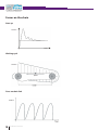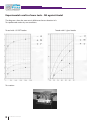
1
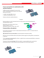
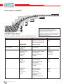
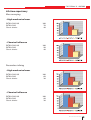
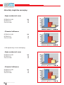
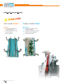
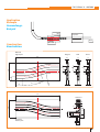
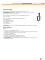
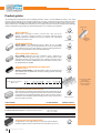
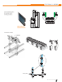
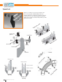
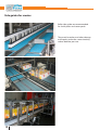
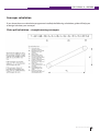
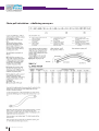
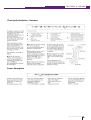
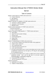
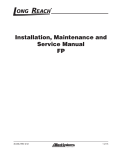
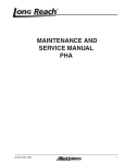
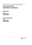
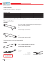
APPLICATIONS Inclined and declined conveyors Maximum angles Chain type lubricated Dry Stainless steel 4° 8° Plastic chain/belt 2.5° 4.5° High friction chains steel/plastic 12/15° 15/20° *Dry run with steel chains is generally not recommendable Pollution on the chain as well as on the product surface influences the maximum angles negatively. Drive construction Declines tan (critical angle) = coefficient of friction chain/belt against product, considering pollution >8° Soft start/stop is reccomended. <8° Soft start/stop is recommended. Dynamic tensioner is in both cases recommended. Inclines Drive is normally located at the upper end. Soft start/stop is recommended. Integrated transfer separate transfer e.g. with dead plate Hold down guide, resp. TAB chain 40 E N G I N E E R I N G M A N UA L E.M. Edition 14 • 06/2006 Curve construction in combination with inclines/declines Sideflexing chains for Magnetic System can be used in inclined/declined conveyors only under the following restrictions: Incline is possible before a curve Decline is possible after a curve Otherwise the chain could be lifted out. Example Recommendation: install a separate drive for curving sections, that are located between inclined/declined sections. High friction inserts of our chains have a Shore A hardness of 70+/-4. Applicable temperature range –40 to +80°C. Accumulation of products Accumulation of products results in increased load on the chain as well as in increased wear on chain/belt and product. LBP (Low Back Pressure) chains/belts are recommended to avoid these effects. With low noise accumulation rollers the friction and other negative resulting effects are reduced to a minimum. For the return part construction flat surfaces or guide shoes are recommended. Roller or serpentine wearstrips are not possible. Frequent and thorough cleaning of LBP chains/belts is recommended to make sure that the accumulation rollers run free. Otherwise the advantages of this construction get lost. Example E N G I N E E R I N G M A N UA L 41 Pressureless combiner Suitable chains/belts Usually pressureless combiners have a track pitch of 85 mm. Type Stainless steel chains Characteristics Extremely close tolerances in terms of: Flatness, surface finish, no sharp edges. Suitable for Glass PET LF, XPG, NG * K330 2250 FT, FTP2 2250 FG, FGP2 2250 M FT 2250 M FG * K330 Low friction. PET Cans FG series: PET, Cans FT series: Glass, PET 2251 FTP2 * K330 2252 FTP2 * K325 With Positioner. Closed surface. Heavy duty design. Low friction. Excellent stiffness. 1” pitch. Glass PET Cans 2120 FTP2 * K330 2121 FTP2 * K325 With Positioner. Closed surface. Low friction. Excellent stiffness. 1/2” pitch. Small transfer radius Cans PET Glass * K330 SPEED-LINE Plastic chains Belts 42 E N G I N E E R I N G M A N UA L * K330 (83.8mm) width is recommended because the gap between adjacent chains/belts is reduced to the minimum. Production tolerances as well as temperature elongation must be considered. * K325 (82.5) width is necessary for sloped pressure less combiners. With Positioner. Closed or open surface. Low friction. Excellent stiffness. 1” pitch. E.M. Edition 14 • 06/2006 Optimised steel chains For maximum product stability e.g. PET bottles, designer bottles and for critical applications e.g. inliners and pressureless combiners we offer the following chains. 9.8 13.5 3.1 42.1 27 Stainless stell chains for Magnetic System: SPC 881 MO SPS 881 MO RD=80 SC 6.6 For sideflexing applications: 38.1 Ø 6.35 R. Design Features: Optimized plate in terms of • Flat and smooth surface o Defined convex shape of plate • Maximum closed plate surface 38.1 TRAVEL 6.6 9.8 3.1 RD For straight running applications: 42.1 Standard stainless stell chains. 38.1 38.1 44 Our staight running stainless stell chains offer design features as mentioned above in standard execution. Ø 6.35 G TRAVEL G (gap) = 1.5 mm minimum For side transfer applications: Stainless stell chains as described above in K330 (83.8 mm) width for 85mm track distance. The gap between adjacent tracks is reduced by approx. 50% (compared to K325 - 82.5 mm chains) to a minimum in order to avoid toppling products. E N G I N E E R I N G M A N UA L 43 HB pins for extended wear life standard pins Chemical Resistant Regular applications • • • 44 Clean environment / proper cleaning and lubrication Low speed and load Regular cleaning with aggressive chemicals E N G I N E E R I N G M A N UA L HB pins Generally both are suitable • • • • For high Load and Wear Resistance Abrasive environment / dirt like crate conveyors / return bottles High speed and short conveyor like in filler area High speed and load Low speed , high load like in accumulation areas and full crate transport E.M. Edition 14 • 06/2006 Life time expectancy Mass conveying • High mechanical wear EXTRA PLUS HB EXTRA PLUS Classic chains 100 70 40 • Chemical influence EXTRA PLUS HB EXTRA PLUS Classic chains 100 90 40 Pressureless inlining • High mechanical wear EXTRA PLUS HB EXTRA PLUS Classic chains 100 60 30 • Chemical influence EXTRA PLUS HB EXTRA PLUS Classic chains 100 80 30 E N G I N E E R I N G M A N UA L 45 Have duty single line conveying • High mechanical wear EXTRA PLUS HB EXTRA PLUS Classic chains 100 50 20 • Chemical influence EXTRA PLUS HB EXTRA PLUS Classic chains 100 70 20 Life expectancy in case conveying • High mechanical wear EXTRA PLUS HB EXTRA PLUS Classic chains 100 50 30 • Chemical influence EXTRA PLUS HB EXTRA PLUS Classic chains 46 E N G I N E E R I N G M A N UA L 100 70 30 E.M. Edition 14 • 06/2006 Crate conveying Usually single track stainless steel chains 71/2 “ wide are used for that purpose. Two track 3 1/4 “ stainless steel chains installation is also possible. Special plastic chains are available for conveying of heavy crates, boxes and kegs especially in dirty environment under rough conditions. Ø 11 14.5 63.5 38.5 19 28.5 Ø 9.5 82.5 63.5 82.5 50 42 118 TRAVEL R. R. TRAVEL CC600 CC1400 For straight sections ferritic stainless steel profiles with a surface finish of max. 1.6 µm and a hardness of 25 HRC are recommended. All edges should be chamfered. To ensure proper operation and long wear life, the CC chain should not be tensioned in the return part. Lubrication is not recommended and in most cases not required anyway. Curve constructions should enable easy removement of debris. Open design is recommended. The chain should be removable out of the curve for cleaning purposes. Inside guides can be made of plastic, however, stainless steel is recommended to avoid imbedding of dirt in the guides, that would reduce the wear life of the chain. Transfers Slave drive dead plate staggered conveyors E N G I N E E R I N G M A N UA L 47 Gripper chains applications General instruction / recommendations Chains tracks must parallel before installing the chains. The tolerance for the parallel adjustment of the tracks is <2mm. Incorrect adjustment can lead to overloading and rapid wear. It is very important to regard the orientation of the gripper ribs. They must be bent backwards relative to the running direction of the chain. The control system of the conveyor must assure that no backline pressure is created. Backline pressure damages gripper chains. The clearance between the chain tracks must be adjustable. The gripping forces must be adjustment according to the product: general rule: as tight as the product can still be removed manually. This is usually 5 to 10 mm less than the product width / diameter. It must be avoied that grippers touch each other e.g. by too tight adjustment. Touching grippers loose their elasticity what can result in damage as weel as production stand still. A tensioning system is strongly recommended. Overstressing the chain by too strong tension must be avoided. It is of major importance to avoid touching products. If products touch each other while being clamped by the gripper chains, they cause damage. It is e.g. recommended to set the speed of the feeding conveyor a little slower than the speed of the gripper conveyor.This ensures a gap between the products, which is necessary. Summary of recommendations: • Continuous operations, no start / stop • Run the gripper elevator empty before a line stop • Use frequency controlled drivers with soft start / stops • If lubrication is necessary, PermaLub devices are preferred, grease lubrication is not recommended because the grease binds dirt and creates wear. • Continuous inspection is strongly recommended • Avoid: • Too tight adjustment of the tracks • Misaligned tracks and / or sprockets / wheels • Touching products • Collision points with parts of the conveyor construction. 48 E N G I N E E R I N G M A N UA L E.M. Edition 14 • 06/2006 Orientation of gripper ribs Elevator Crate turner E N G I N E E R I N G M A N UA L 49 Gripper chain assembly instruction SIDEFLEXING PLASTIC PLATE TOP CHAINS WITH GRIPPERN SNAP ON (BASE ROLLER CHAIN 19.05 mm - 3/4 inch - pich - side bow type) Instruction for the assembling/disassembling of the plate and the rubber (GSI - for light applications,GS2 - for heavy applications,GS3 - for special applications Picture 1:Connecting of two assembled chains with a connecting link Picture 2:Assembling of the plastic plate. Step 1:heat to about 70° centigrade heating treatment time:20 sec Picture 3:Assembling of the plastic plate Step 2:Assembling in the show way Picture 4:Disassembling of the rubber Attention! push out the pin in direction OUT Picture 5:Assambling of the rubber Attention!assemble the pin in direction IN Picture 6:Cut the chain in the wished leght Attention!use a compact base Lubrication: You have to check the lubricationof the roller chain at regular intervals! 50 E N G I N E E R I N G M A N UA L E.M. Edition 14 • 06/2006 PRODUCT HANDLING Conveyor length Conveyor length depends on Chain/belt type Lubrication Product Load Etc. Type Stainless steel, straight Stainless steel, sideflexing Plastic chains, straight Plastic chains, sideflexing Max. advisable length [m] Approx. 15 Approx. 12 Approx. 9-12 Approx. 9-12 Only valid for standard conditions. For long conveyors it is recommended to place curves close to the idler end in order to reduce chain load resulting in longer wear life. A phenomenon, called slip stick effect occurs unpredictably. It depends on speed, load, construction and lubrication. Pulsating dynamic forces are the result and affect the service life of all components of a conveyor. Long conveyors should be avoided in such cases. Long conveyors result in high chain load, which affects all components of the conveyor and reduces their wear life. Conveyor speed Maximum m/min Type Stainless steel, straight Stainless steel, Magnet System Plastic chains, straight Plastic chains, sideflexing, Magnet System Plastic belts, straight Dry 50 30 80 50 80 Lubrication Water 70 40 100 90 100 Water & soap 130 130 180 180 180 Under abrasive conditions the maximum speed is reduced. E N G I N E E R I N G M A N UA L 51 STM Safe Transfer Module Safe Transfer Module Sicherer Transfer Modul Features Merkmale Safe and smooth Transfer of instable products Compact design, one solid piece, no edges Easy installation Sicherer und sanfter Transfer instabiler Produkte Kompakte Ausführung einteilig, keine Kanten / Übergänge Einfache Installation 52 E N G I N E E R I N G M A N UA L E.M. Edition 14 • 06/2006 Application Example AnwendungsBeispiel drive Inspector drive Idler end Construction Konstruktion Oberteil Upper part Magnet Bevel TAB 6.25 9.5 13.5 19 8.5 85 85 41.5 50 45 44 270 85 Magnet 100 R500 100 100 27 27 27 625 Universal 63 23 23 R5 50 87 65 58 45 85 270 23 Unterteil Return part 8 8 50.5 E N G I N E E R I N G M A N UA L 53 Static electricity AS material has the following properties: According to IEC60093 test method Surface resistivity: Volume resistivity: 105 Ohm 105 Ohm m General instructions / recommendations: Caution! Already during transportation of the chains electric charge can be generated what can cause sparks. Before carrying the chains into an explosion hazardous area any electric charge must be dissipated from the chain. Disharging can be done for example by brushing the chains with a grounded and conductive wire brush. The chains must be grounded, respectively included in the potentialequalisation of the plant. It must be assured on site that the electric charge is dissipeted to the ground preventing any damage. Grounding of the chains can be achieved by appropriate wear strips and by appropriate sprockets and idler wheels. By means of conductive and grounded wire brushes electric charge can be removed directly from the surface of the chains. Wear strips must be conductive and grounded. Damage at chains (wear) caused by wear strips must not exceed the admissible limits. Caution! Wear at chains must not lead to lay open the metallic pin which might scratch over other metallic surfaces and generate sparks. Sliding properties of wear strips must admit save operation of the chains. Chain breakages must be avoided. Caution! Chains breakages can cause impact sparks. Construction, layout and control system of the conveyors must permit a save operation of the chains. The chain speed must not exeed 1 m/s. Sprockets and idler wheels must be conductive and grounded. In case a system of rollers is used for the return of chain the same is applicable for the return rollers as for sprockets and idler wheels. (see 16) The resistance of the grounding must not exeed 1MOhm (=10^6Ohm = 1000000Ohm). The resistance of the grounding must be checked by the assembly fitters prior to installing the chains. During assembly / installation of the chains sparks must be avoied. Appropriate tools must be used. Chain pin must be installed completely and carefully. After the chais pin installation the chain links must be checked and in case of any damage be replaced. Swarf and any other metallic or sparking objects must be removed from the conveyor prior to start -up. The total chain length of a grounding section must not exceed 333 chain links. 54 E N G I N E E R I N G M A N UA L E.M. Edition 14 • 06/2006 Product stability A product stands stabile even in case of large speed variation if C > R. Critical coefficient C=B/H. Real coefficient R=real friction coefficient, measured for the application in question. Raised edges however have to be avoided. With the following formula the maximum admissible speed variation can be calculated: Max. admis. speed variation MSV* = SQR(2*g*SQR(H2+B2)-H) SQR = square root g = gavitational acceleration H = height of centre gravity B = base radius G = centre of gravity G H B *MSV indicates e.g. the max. admissible speed of a bottle being conveyed onto a dead plate without tilting Noise reduction Measures: Use curves instead of dead plate transfer. Install flow control devices like frequency controlled drives to adjust the conveyor speed according to actual requirements (e.g. accumulation stop). Cover guiderails with plastics. Use plastic sprockets and idlers. Use plastic wearstrips in combination with steel chains. Use return part rollers with a larger diameter than 60 mm. Apply lubrication. Use Magnetic Corner Tracks in EXTRA execution with profiled stainless steel sheet metal insert or Nolu-S material. E N G I N E E R I N G M A N UA L 55 Product guides The conical guide rail incorporates two outstanding materials: stainless steel and UHMW. The stainless steel sheath provides rigid streamlined support for heavy loads at any speed, plus a solid connecting point for holding the rail in place with clamps and brackets. The UHMW guiding surface is available in a wide selection of shapes. The very low friction characteristics of UHMW allow containers to move at high speed with a minimum of drag, container damage, and noise. Materials are approved by the FDA and accepted for use in USDA inspected facilities. Stainless steel METAL PROFILE Metal profile is typically in stainless steel AISI 304 ( AISI 316 on the request), used for its excellent resistance to corrosion and long lasting attractive appearance. Galvanized steel can be ordered as an economical alternative to stainless steel. Zinc plated steel 304 Stainless steel Low friction UHMW guiding surface STANDARD VERSION Natural UHMW - The manufacturing process allows the use of UHMW without additives or other processing chemicals. The result is a material that resists abrasion better,is more color stable (less prone to yellowing) and of uniform consistency. Available in two colors black and white. SELF LUBRICATED VERSION Nolu-S UHMW - Battleship grey color. A lubricant system is added to our standard UHMW during processing to give it reduced friction while maintaining all other physical properties. The coefficient of friction Nolu-S material is ca 35% lower as standard. The PV-limit for chain is at least 2 times the standard value for UHMW. VERSION WITH IMPROVED ELECTROSTATIC CONDUCTIVITY Polyethylene UHMW NOLU S Polyethylene Nolu-S UHMW PE as Static Dissipating UHMW - Special formulation retains the low friction and wear characteristics of UHMW while effectively reducing problems caused by static. Color: black. Polyethylene UHMW Antistatic Antistatic Polythylene Specific electrical resistance (Ohm x cm) 10-6 10-4 10-2 100 Pure compressed Carbon black Metals 102 Conductive Compounds 104 106 Antistatic Compounds 108 1010 1012 1014 Static dissipative UHMW rail provides a conductive pathway to disperse the buildup of static electricity. 1016 Plastic Standard UHMW VERSION FOR HIGH TEMPERATURE High temperature.Special developed material to operate under high temperatures. The HT profiles are designed to operate under a continuous temperature of maximum 270°C.Typical applications for HT profiles are: Ovens, cookers, hot fill area, steam chambers, furnace discharge, retorts, fryers, shrink tunnels, pasturizers and steam boxes. SPECIFICATIONS 2 Tensile Strength - ASTM D-1457 (N/mm ) Deformation under load - ASTM D-621 (%) Coefficient of thermal expansion - ASTM D-696 mm/mm/°Cx10-5) Coefficient of friction - ASTM D-1894 Continuous service temperature For use in high temperatures HI-TEMP MATERIAL MATERIAL PROFILE 12.6 3.8 7.47 ( 37°-120°C ) 12.62 ( 120°-150°C ) 7.47 ( 150°-270°C ) 0.04 270°C 500 - VERSION WITH NYLATRON INSERT For applications such as high conveyor speeds, heavy loads or abrasive conditions. Nylatron can be used at continuous temperatures up to 93°C. 56 E N G I N E E R I N G M A N UA L Nylatron E.M. Edition 14 • 06/2006 Special product guides for labelled bottles avoiding scratches SIDE GUIDE FOR LABELLING BOTTLE Installation example 13S00250 Heavy duty E N G I N E E R I N G M A N UA L 57 Speed set Adjusts to 3 container sizes! SpeedSetTM brackets offer preset conveyor guide rail adjustability that is fast accurate without the need for tools. A simple push on the end knob moves the pin, clamp and guide rail. Spacing blocks, cut the length needed, accurately hold the pin and guide rail in position. A Positioning Spacers u dj st tw id os es Push Knob A Piston Rod u dj st on id es es Spring Rod Sleeve Brackets ra l le l 13S00260 m ds Ro Range of travel us tb e pa Range of travel Largest container ds m us tb e pa ra l le l Smallest container Ro Single side adjusting Double side adjusting 58 E N G I N E E R I N G M A N UA L E.M. Edition 14 • 06/2006 Adjustable splicing clamp Required for adjustable curve product guides GR IN D I SL R ED X I F AIL AIL SpeedSet E N G I N E E R I N G M A N UA L 59 Side guides for creates Roller side guides are recommended for shrink packs and carton packs They avoid scratches and other damage at the packs and at the same time they reduce backline pressure 60 E N G I N E E R I N G M A N UA L E.M. Edition 14 • 06/2006 CALCULATION Required data for chain calculation Chain and material specification Chain type Curve material Material straight upper part Material straight return part Product material Product details and conveyor specification Products/hour Product weight Chain speed Lubrication Number of tracks Sprocket size Diameter product Height difference Power consumption [g] [m/min] [teeth] [mm] [mm] [Watt] Conveyor layout from idler to drive Section Length Angle [mm] [°] Radius Accumulation Occupation [mm] [%] [%] 1 2 3 4 5 6 7 8 9 10 Required operation data Please add a sketch of the conveyor layout. Please describe operation conditions (e.g. abrasive conditions, environmental conditions, special operation requirements) in detail. Please describe product features in detail, add drawings/sketches. Replacement of chain/belts Which chain/belt was used before? Did it work satisfactory or did problems occur? SysCalc Please contact your Flexon System Plast partner or our technical support department. E N G I N E E R I N G M A N UA L 61 Required data for belt calculation Belt and material specification Belt type Belt width Material straight upper part Material straight return part Product material [mm] Product details and conveyor specification Products/hour Product weight Belt speed Lubrication Sprocket size Diameter product Height difference Power consumption Centre drive Section [g] [m/min] [teeth] [mm] [mm] [Watt] [yes/no] Length Accumulation Occupation Temperature [mm] [%] [°C] [%] 1 2 3 4 5 Required operation data Please add a sketch of the conveyor layout. Please describe operation conditions (e.g. abrasive conditions, environmental conditions, special operation requirements) in detail. Please describe product features in detail, add drawings/sketches. Replacement of chain/belts Which chain/belt was used before? Did it work satisfactory or did problems occur? Please contact your Flexon System Plast partner or our technical support department. SysCalc 62 E N G I N E E R I N G M A N UA L E.M. Edition 14 • 06/2006 Conveyor calculation If you do not have our calculation programme installed, the following calculation guide will help you to design/calculate your conveyor. Chain pull calculation – straight running conveyors E N G I N E E R I N G M A N UA L 63 Chain pull calculation – sideflexing conveyors 64 E N G I N E E R I N G M A N UA L E.M. Edition 14 • 06/2006 Chain pull calculation - elevators Power absorption E N G I N E E R I N G M A N UA L 65 Coefficients of friction Below listed coefficients can be used as a guideline. Dependent on environmental and application requirements (temperatures, lubricant, material combinations, dirt/debris, product and chain/belt surfaces, etc.) the coefficients are subject to variation. Coefficients of friction are subject to permanent tests in our laboratories. Coefficient of friction between chain and wearstrip Chain/belt material Lubrication SSE SPS Dry Water Water&soap Oil Dry Water Water&soap Oil Dry Water Water&soap Oil Dry Water Water&soap Oil LF-Acetal (D, W) XPG-Acetal NG-PBT Stainless steel, C-steel 0.50 0.40 0.20 0.20 0.30 0.23 0.15 0.10 0.25 0.20 0.15 0.10 0.22 0.20 0.15 0.10 Wearstrip material UHMWPE Nolu-S PA 0.40 0.37 0.30 0.28 0.20 0.19 0.20 0.19 0.25 0.22 0.21 0.19 0.15 0.14 0.10 0.10 0.20 0.17 0.18 0.16 0.15 0.14 0.10 0.10 0.18 0.15 0.16 0.14 0.15 0.14 0.10 0.10 Return Extra With metal strip for roller M & TAB chains 0.20 0.15 not 0.10 applicable 0.20 0.15 0.10 0.19 0.17 0.12 0.20 0.15 0.10 0.16 0.14 0.13 0.20 0.15 0.10 0.13 0.12 0.11 Coefficient of friction between chain and product Chain/belt material Lubrication Stainless steel, steel Speed-Line Dry Water Water&soap Dry Water Water&soap Dry Water Water&soap Dry Water Water&soap Dry Water Water&soap Dry Dry LF-Acetal (D, W) XPG-Acetal NG-PBT LBP VG 66 E N G I N E E R I N G M A N UA L Paper, cartoon 0.40 0.40 0.35 0.30 0.30 0.10 0.60 Metal (steel) 0.50 0.40 0.20 0.50 0.40 0.20 0.30 0.23 0.15 0.25 0.20 0.15 0.25 0.20 0.15 0.10 0.73 Product material Plastics Glass incl. PET (return) 0.30 0.47 0.25 0.31 0.15 0.21 0.27 0.40 0.23 0.26 0.13 0.18 0.21 0.24 0.16 0.18 0.13 0.14 0.18 0.20 0.14 0.15 0.12 0.12 0.13 0.14 0.12 0.13 0.10 0.11 0.10 0.10 0.50 aluminium 0.35 0.30 0.20 0.32 0.27 0.19 0.25 0.18 0.14 0.20 0.15 0.13 0.15 0.14 0.12 0.10 0.50 New glass, ceramics 0.35 0.30 0.15 0.29 0.24 0.13 0.20 0.15 0.12 0.15 0.13 0.12 0.12 0.12 0.10 0.10 0.50 E.M. Edition 14 • 06/2006 Parameters causing wear Operating conditions Load Speed Number of starts per hour • Starts with/without load • Soft start/frequency inverter controlled drive Product accumulation • Conveyor control system (PLC) Lubrication Water quality • Concentration of chlorines • Water hardness • Contaminations • Capacity of water supply Lubricant • Suitability/performance • Dosing • Efficiency of nozzles Cleaning Cleaning agent • Frequency • Intensity • Rinsing Chemical attack Environment Temperature Humidity Wear increasing media/abrasives Corrosion Cleanness • Soil e.g. from construction work Conveyor components Material quality Construction Dimensional accuracy of • Wear strips • Sprockets • Idlers • Return rollers • Shaft alignment Conveyor construction Choice of chain/belt/suitability of selected chain/belt for the application Catenary design • Tensioner Sprocket construction • Tooth geometry • Pitch line clearance • Number of teeth/polygon effect Return part construction • Smooth feed in • Sliding/rolling Mounting of wear strips • Flatness • Chamfers • Raised portions • Extension compensation gaps Lubrication system Cleaning system Changed/modified conditions Changed operating conditions Modification of conveyor or it’s parts/components • Maintenance • Overhaul E N G I N E E R I N G M A N UA L 67 Forces on the chain Start-up Tension Time Working cycle Tension Force on chain link Tension 68 E N G I N E E R I N G M A N UA L E.M. Edition 14 • 06/2006 Forces in the curve PV PV = pressure x velocity PV [W] = P [N/ mm2] x v [m / s] P = f (F1,F2,A), A = contact surface PV is a material property and indicates the wear resistance. The higher the PV, the higher the generated heat, the higher the wear being a function of the heat. Different pressure and different velocities lead to different wear rates. The effect is amplified dynamic operating conditions as shown above. E N G I N E E R I N G M A N UA L 69 Experimental results of wear tests - NG against Acetal The diagrams show the wear rate in 0/00 over the test duration in h. Test performed under dry run conditions. Tested with 1.5 l PET bottles Test station 70 E N G I N E E R I N G M A N UA L Tested with 1 l glass bottles E.M. Edition 14 • 06/2006 MAINTENANCE Lubrication Synthetic lubricants offer: Concentration independent on water properties e.g. hardness. Less foam. No slippery factory floors. Less bacteria growth. Soap based lubricants offer: Best possible lubrication, because lubricant sticks to the chain. Lubrication suppliers’ advice is strongly recommended. Aspects of dry running conveyors: Savings on investment (lubrication system, lubricant, water treatment, etc.). No packaging damage. Increased coefficient of friction and therefore wear. Extra cleaning required. Slip stick effect possible. Built up of electrostatic charges possible. Higher noise level. Not applicable for high speed applications. Dirt and debris must be removed by cleaning to avoid increase of coefficient of friction and wear on all components of the conveyor. E N G I N E E R I N G M A N UA L 71 Cleaning Cleaning is most important in order to achieve: Hygienic system Clean products Reduction of friction and wear Removal of abrasives Removal of remaining cleaning agents with flush water is recommended. Cleaning dry running conveyors With dry running conveyors there is no continuous cleaning like with lubricated conveying. All products (beer or lemonade) spilled on the chain/belt will result in pollution of the containers, increasing the friction, and the risk of products toppling over. Therefore dry running conveyors should be cleaned even more frequently than lubricated chains. How often depends very much on the circumstances, e.g. when liqueurs are bottled and spilled, it might be necessary to clean every time the line stops for a few hours. Cleaning stainless steel chains This type of chain will be lubricated in most cases. Dirt etc. is flushed away continuously. Normally, it is recommended to clean the chain regularly with hot water (max 80°C) or cold water with a cleaning agent to stop and remove any form of bacteria growth. There are often positions where product (beer or soft drinks) is spilled on the chain. In these positions the lubrication will not function optimally, and a more frequent cleaning could be required, e.g. once every week. It could be necessary to use a brush in addition to the hot water or cleaning agent to remove e.g. broken grass etc. 72 E N G I N E E R I N G M A N UA L E.M. Edition 14 • 06/2006 Cleaning plastic chains For lubricated plastic chains, almost the same counts as for stainless steel chains. But when using cleaning agent attention should be given to its compatibility with the chain material. With respect to cleaning, it is obvious that the Magnet System offers great advantages because the chain can be taken out of the curve and cleaning takes less time than with conventional curve systems. Cleaning plastic belts Basically, cleaning of plastic belts is not different from cleaning plastic chains. Again, the chemical resistance of the materials against the cleaning agents must be checked beforehand. Flat Top belts have to be cleaned from the top and underside. Flush Grid belts can be cleaned very effectively, due to the open area. Water can be sprayed through the belt to clean it. Inspection A good condition of the line can be maintained when people recognise initial signs of wear/failure and react accordingly. Generally, all components of a conveyor should be checked at once. Check the condition of the chain/belt regularly, and replace links/modules which are damaged. Important in this matter is to try to find the cause of the damaged links/modules. Wear patterns or damage on a chain or belt can often lead to a problem area elsewhere in the conveyor. It is very important to replace damaged modules in plastic belts and links in plastic chains as soon as possible since small damage could lead to bigger damage if it is not repaired. If any damage is found such as pieces of plastic broken off, or a wear pattern at the side of the belt, the cause of the problem should be located. E N G I N E E R I N G M A N UA L 73 Cleaning instructions General remarks Cleaning of chains and belts is necessary for the following reasons: Minimization of dirt / debris Minimization of germ formation Minimization of product scarp Maximization of production stability / continuity Clean operating conditions substantially improve: Service life of chains and belts Service life of components e.g. wear strips and return part components Prevention of crashes caused e.g. by glass debris and wrapping debris Prevention of malfunctions caused e.g. by sticky residues. Careful cleaning includes all components of a conveyor: All components which are in direct contact with chains / belts All components which affect indirectly the service life of chains / belts such as return shafts: • Upper side of chains / belts • Opposite side of chains / belts • Wear strips / rollers in the return part • Wear strips in the upper part • Sprockets and idler • Shafts of return rollers and idler • Return guide shoes Cleaning schedules depend on: Production requirements Actual cleanness of chains / belts Any case a conveyor should be cleaned before the first start-up in order to remove all dirt/debris/residues from the assembly.The same should be done when a conveyor is restarted after a longer period out of order. We recommend permanent inspection of the actual cleanness of conveyors and chains / belts. If extraordinary cleaning is required this should be done without delay. Regarding the choice of cleaning agents the followuing must be considered: Chemical resistance of the chain/belt materials Example: • pH 7 (neutral) is recommended • recommended pH range4-10 • Chlorine (warm), Ammoniac (warm) should only be used in very low concentrations <7%. Only short contact time is allowed. • Strongly caustic agents e.g. phosphoric acid (warm) ,salt acid,formic acid,sulphuric acid,(warm),saltpetre acid,potassium hydroxide,sodium hydroxide,hydrogen peroxide (warm) and solvents like Acetone should be avoided with plastic chains / belts. Using cleaning agents the following should be considered: In the actual catalogues On our internet site:www.systemplast.com/documenti/chemicalpg.htm In the Engineering Manual In case of doubts/question don’t hesistate calling us. 74 E N G I N E E R I N G M A N UA L E.M. Edition 14 • 06/2006 Cleaning process Selection of the best suitable cleaning process can only be done by the plant operator according to the special requirements and circumstances of his production unit. We are only able to give general recommendation based on our experience. In any case our recommendation must be checked carefully by the plant operator reading applicability. Pre-cleaning Stop conveyor,remove debris e.g. broken glass,wrapping piecies,cords,wood piecies • Also in the return part means: • cold/warm water up to 60°C • brush,hose,pressure cleaner up to 80 bar If possible let the conveyor run.Clean it from all sides:driet dirt,germ,sticky dirt Sprockets,idlers Upper chain/belts guides Guides in the return part Cleaning means: • cleaning solution and user manual of cleaning agent supplier • brush,perssure cleaner to apply the cleaning solution If possible let the conveyor run.Clean it from all sides.Make sure that all surface with cleaning solution. Sprockets,idlers Upper chains/belts guides Guides in the return part regards the recommended exposure time of the cleaning agent Rinsing means: • cold/warm water up to 60°C (regard recommendations of the cleaning agent supplier) • brush,hose,pressure cleaner up to 80 bar If possible let the conveyor run.Rinse it from all sides. Sprockets,idlers Upper chain/belts guides Guides in the return part Repeat these steps until the favoured cleaning result is reached. E N G I N E E R I N G M A N UA L 75 Disinfection Is necessary to prevent alternating contamination of chains/belts and product. means: • disinfection agent and user manual of the supplier • brush,pressure cleaner If possible let the conveyor run.Disinfects it from all sides.Make sure that all surface are convered with disinfection solution. Sprockets,idlers Upper chain/belts guides Guides in the return part regards the recommended exposure time of the disinfection agent Rinsing means: • cold/warm water up to 60°C (regard recommendations of the cleaning agent supplier) • brush,hose,pressure cleaner up to 80 bar If possible let the conveyor run.Rinse it from all sides. Sprockets,idlers Upper chain/belts guides Guides in the return part Drying/blowing off Die to the fact that it most cases drying the conveyor completely is not possible it is recommended to remove at least big water residues. Inspection Check the cleaning result carefully (all components) and repeat the procedure if necessary. Before re-starting the conveyor make sure that all cleaning means were removed. Other components This cleaning procedure is also applicable to other components of a conveyor which are not in direct conact with chains/belts: Basic construction:pads.pods.clamps Product guides:guide rails,side brackets,traverses, clamps Drives,supports,sensors,casing:regard special instructions about cleaning electric devices! 76 E N G I N E E R I N G M A N UA L E.M. Edition 14 • 06/2006 Critical sections of a conveying line which need special attention regarding cleaness This list considers standard layouts conveying lines.In those sections ,the danger of high wear is significant.For this reason cleanness is essential to increase service life of all components and to avoid malfuctions as well as product scrap. Return boxes all the way to the de-cases or washer Return boxes all the way to the washer One way and return bottles in high speed section: • filler • labeller One way and return bottles in side transfer sections and pressure less combiners One way and return bottles in accumulation tables and buffer section in front of machines: • filler • labeller • pasteurizer Create conveying in the dry end Generally it must be noticed that dry sections must be inspected very carefully regarding clean conditions. In such sections no permanent cleaning by means of lubrication spray devices is taking place. As a consequence out of insufficent cleaning wear at the following components can be observed: curve guides wear strips chains/belts return components Only due to the higher friction in such sections the wear rate is already higher compared to lubricated section.If cleaned properly,the service life of components can be increased significantly. Additionally to regular cleaning cycles it is recommended to blow off particularly the curve guides in short intervals. EXTRA curve guides with metal wear recommended anyway. E N G I N E E R I N G M A N UA L 77 Inspection procedure 1. 2. 3. 4. 5. 6. 7. 8. 9. 10. 11. 12. Inspect chains for unusual wear patterns,nicks,or damage. Look for excessive gaps between chain flights. Check conveying surface for flatness,bent or broken flights. Inspect hold-down tabs or beveled sliding surfaces for excessive wear. Review chain catenary sag for proper amount. If take-ups are used,check that take-up tension is not excessive.Do not preload chain. Check all idlers,rollers,turn discs and sprockets for freedom of rotation. Examine sprockets for excessive wear. Look for debris build up in sprocket tooth pockets. Check for excessive guide ring wear. Check all wear strips and fasteners for excessive wear. Check all transfer points,dead plates,turn tables,turn discs and sprockets for proper elevation and alignment. 13. Review function of lubrication system. 14. Inspect general cleanliness of conveyor system. 78 E N G I N E E R I N G M A N UA L E.M. Edition 14 • 06/2006 Installation procedure 1. Check all sprockets,idlers,turn discs and rollers for proper elevation and alignment with regard to the conveyor tracks. 2. Check all wear strips (carrying and return),dead plates, dividers and transfers mechanism for proper location, elevation, spacing and flatness. 3. Check all fasteners for proper tightness (torque).Fasteners used on wear strips and dead plates must have recessed heads. 4. Check all conveyor splice points for proper elevation,alignment and fastening. 5. Inspect conveyor system for obstructions by pulling a short section of chain (1 metre) trought the entire conveyor. 6. Check lubrication system (if present). 7. Install conveyor chain, assuring that the following has been done: A. Check for correct direction of chain travel. B. Assemble chain in 3 meters sections and avoied twisting or damaging the chain. C. Connect chain sections on the conveyor.Insure that all pins and top plates are flush and propely secure. D. Adjust chain catenary (sag) to the proper elevation.Note:Readjustment is usually necessary following operation under loading conditions. Although not to overload the chain. 8. Insure that lubricant is evenly dispersed through conveyor system.See lubrication section for more information. 9. Start up conveyor by jogging and/or using short running periods before loading the system. Be alert to unusual noises or actions.If problem should occur ,refer to the trouble shooting guide. E N G I N E E R I N G M A N UA L 79 Trouble shooting Chain/belt jumps on sprocket or does not release well Possible causes Chain/belt is elongated e.g. due to wear or overloading Improper catenary sag Sprocket is worn Wrong sprocket type Misaligned sprocket Improper sprocket position Slip stick operation Possible causes Slip stick Return roller diameter too small Chain/belt catches the conveyor Damaged chain hinges Possible causes Overloading Blocking and obstructions Exceeding the minimum backflex radius Elongation Possible causes Overloading Remedy Replace chain/belt and sprocket. Check other components as well. Check dimensions and adjust Replace sprocket Install correct sprocket Check and adjust Check and adjust position Remedy Use lubrication. Reduce chain/belt tension by shortening the conveyor Install larger rollers Remove obstructions. Check return part as well Remedy Replace chain/belt. Check sprockets and other components as well Check the complete conveyor Check conveyor construction Wear from dirt in hinges Remedy Replace chain/belt. Check sprockets and other components as well Improve cleaning Rapid curve wear Possible causes Overheating Embedded abrasives Remedy Use EXTRA curve Replacement Chain drifts sideways on sprocket Possible causes Bad shaft/sprocket alignment Conveyors is not level Remedy Adjust or use collars Adjust 80 E N G I N E E R I N G M A N UA L E.M. Edition 14 • 06/2006 Cracked hinge eyes Possible causes Stress-corrosion caused by incompatible chemicals Chains for Magnetic System come out of curve Possible causes Worn curve Improper chamfering of the infeed Or other obstructions No controlled start-up Curve not mounted level Rusted steel chain Possible causes Incompatible combination of chain material and chemicals. May occur even with stainless steel. Excessive chain/belt wear Possible causes Pollution Failing lubrication Obstructions Debris in return part Remedy Replacement. Check chemicals Remedy Replacement Check and adjust/rework Install frequency inverter drives Check and adjust Remedy Use only compatible chemicals Consider higher graded material Remedy Improve cleaning Contact lubricant supplier Check all sections Cleaning. Install roller with larger diameter Sprockets don’t slide on shaft when belt extends due to temperature increase Possible causes Remedy Pollution Improve cleaning Axial fixing incorrect Re-adjust axial fixing according to temperature situation Rapid wear on sprockets Possible causes Abrasive conditions Remedy Improve cleaning Use steel sprockets Please help us completing that list by informing us of your experiences. E N G I N E E R I N G M A N UA L 81 Replacement criteria Chains must be replaced, when Pitch is elongated more than 3%. Thickness of the plate is reduced to less than 50%. The surface becomes very unflat/uneven or rough, dependant on application. Side of sideflexing chains is worn to such an extent, that the pin is exposed. Chain jumps on the sprocket. Chains of inliners/pressureless combiners should be changed all at once. Belts must be replaced, when Thickness of the plate is reduced by 1 mm from the top and from the underside. The surface becomes very unflat/uneven or rough, dependant on application. Belt jumps on the sprocket. As a guideline, 3% elongation is tolerable. When replacing chains/belts, it is recommended to replace wearstrips and sprockets/idlers as well. Replacement of Dual Magnetic Corner Tracks In case of multitrack curves, check all tracks. Curve is worn, when the edge of the chain plate reaches the inner side of the curve. Sprockets and idlers must be replaced, when Teeth show hooked shape and chain releases not well. Teeth are damaged. Chain jumps on sprocket. Bore of idlers is worn out and idler starts oscillating. Hub or keaway are damaged. New chain is installed. Wearstrips must be replaced, when Thickness is reduced to less than 50%. Dirt or debris is embedded. Fixing bolts protrude. 82 E N G I N E E R I N G M A N UA L E.M. Edition 14 • 06/2006 CHEMICAL AGENT Acetic acid Acetone Acrylonitrile Aluminium chloride Aluminium sulphate Amyl alcohol Ammonia Ammonium chloride Aniline Barium chloride Beer Benzene Benzic acid Benzol Boric acid Brine Butter Butyl acetate Butyl alcohol Butyl glycole Calcium chloride Carbon sulphide Carbon tetrachloride Chlorine water Chloroform Chromic acid Citric acid Cyclohexane Cyclohexanol Decalin Dioxane Distilled water Ethyl acetate Ethyl alcohol Ethyl cloride Ethyl ether Ferric chloride Food fats Food oils Formaldehyde Formic acid Freon 12 Fresh water Fruit juice Gasoline Glycerine Hydrocloric acid Hydrofluoric acid Hydrogen peroxide Isopropyl alcohol Lactic acid Linseed oil S S S S S S S S S S S S S L POLYAMIDE POLYPROPYLENE ACETAL RESIN POLYETHYLENE BRASS PA PP POM PE OT .NI. NBR VITON AISI 304 C Note % 23° C C Note % 23° C C Note % 23° C C Note % 23° C C Note % 23° C C Note % 23° C C Note % 23° C C Note % 23° C 10 100 100 10 10 100 10 10 100 10 ★ ● ● ● ● ● ● ● S ❍ ● ● 40 ❍ ● ● ❍ ● ● ● ● ● S ● ● SA SA 100 10 100 100 100 10 100 100 1 10 100 100 100 96 100 100 10 30 10 S S S 10 40 3 S 10 ★ ❍ ❍ ● ● ● ● ● ● ● ● ● ● ● ● ● S ★ ● ● ● ● ● ★ S ★ ★ ● ● S ● 30 10 SA 50 10 96 40 ● ● ● ❍ ● ● ● S ● ● ● ● ● ● ❍ ● ❍ ● ❍ ● ● ● ● ★ ★ ❍ 5 ● ● ● ● ● 3 ❍ ● S S ★ S S ● ● ● ❍ ● ● ❍ ● ● ● ● S SA ● ● S ★ ● S S ● STAINLESS STEEL 20 SA SA SA SA ● SA ● ● ★ ★ ● ● S ● S ★ ★ ● ★ ★ ● ❍ ● S ★ S ● ● ● ★ ★ ● S ● ● ❍ ★ ❍ ❍ S ● ● ● ★ 10 ● ● ❍ ★ 35 70 ● ● ❍ ● ● ● ● ● 35 ● ★ ● ● ● ● SA 50 SA ★ ❍ ❍ ● 40 ● ● ❍ ● ❍ S ★ S 10 65 80 ● S ● ● ❍ ★ ● ● ● ❍ ● ❍ ★ ★ ● ● ★ ★ ★ ● ● ● ❍ ● ● ● ● ● ❍ ● ● ★ ● ❍ ● ● ● ● ● ❍ S ● S ★ ● S ● ● S 20 ★ ★ ★ ● S ● S S 10 30 40 10 ● ● ● ● ❍ ❍ ● ● ● ★ ● ● ● ● ❍ ● ● ● ★ ❍ RUBBER SA 40 37 48 90 ● ● ● ● ● ● ● ● ★ ★ ● ❍ ★ ● ● ● ● ★ ❍ ● ● ● ● ● ● ● ● ● ● E N G I N E E R I N G 20 25 ● ● ❍ ● ● ❍ ● ❍ ● 70 ❍ 100 ● ● SA ● ❍ ● 100 ● ❍ ● 10 ● ★ ● 10 ● 25 ● ● ❍ 10 ● ● ❍ ● ● 100 ● ★ ● ● ❍ ● ● ★ ★ ● ● ❍ ● M A N UA L 83 CHEMICAL AGENT Magnesium chloride Methyl acetate Methyl alcohol Methylene chloride Milk Mineral oil Nitric acid Nitrobenzene Oleic acid Oxalic acid Paraffin Petroleum Petroleum ether Phenol Phosphoric acid Potassium bichromate Potassium bromide Potassium hydroxide Potassium permanganate Sea water Silicone oil Silver nitrate Sodium carbonate Sodium chloride Sodium hydroxide Sodium hypochlorite Sodium silicate Sodium sulphate Soft drinks Suds Sulphuric acid Tartaric acid Tetrahydrofuran Tetralin Tincture of iodine Toluol Transformer oil Trichloroethylene Triethanolamin Turpentine Vaseline Vegetable juice Vegetable oils Vinegar Water and soap Whisky Wine Xylol POLYAMIDE POLYAMIDE POLYPROPYLENE POLYPROPYLENE ACETAL ACETALRESIN RESIN POLYETHYLENE POLYETHYLENE BRASS PA PP POM PE OT .NI. NBR VITON AISI 304 C Note % 23° C C Note % 23° C C Note % 23° C C Note % 23° C C Note % 23° C C Note % 23° C C Note % 23° C C Note % 23° C 10 100 100 100 SA S S S S S S S S S S S S S 10 100 100 10 10 5 10 10 1 10 10 10 10 10 ● S ● ● ● ● ● ★ S ❍ ● ❍ S ● ● ★ ★ ❍ ● ● ★ ● ● ● ● ● ● ● ● ● ● ● ★ ● ● ● ★ ● ● ❍ ● 50 ❍ ● ● ● ● ● ● S S S 20 SA SA S 20 ● 85 10 SA 50 S S 98 10 ● ● ● ● ❍ ★ ● ● ❍ ❍ ● E N G I N E E R I N G M A N UA L 5 ● ★ ● ● ● ● ● ● ● ● ● ● ● ● ● ● ● ● ● ★ ● 5 ❍ ● ● ❍ ❍ ● S 10 ● S ● ● ● 10 25 40 30 ★ ★ ● ★ 95 25 ● ● ❍ ● ● ● ● ● ★ ● ● ● ★ ❍ ★ Data shown in the table was taken from laboratory tests performed on unstrained samples and are merely indicative. Chemical resistance under normal working conditions can depend on various factors, such as stress and temperature, concentration of the chemical agent and duration of its effects. 84 S ● ● ● ● ● ● ● ● ● ● ● ● ● ● ● S RUBBER 40 ● ● ★ S S S S S ● S S ● S S S S S ● ● ❍ ● S ● S ★ S ● ★ ● ● ● ● ★ ❍ ● ● ● ● ● ● ● ❍ ABBREVIATION C = concentration L = liquid SA = saturated S = solution 20 ● S ★ ❍ ★ ● ● ★ ★ ❍ ❍ S ● ★ ★ ❍ ❍ ● ❍ ★ ● ● ❍ ● ● ❍ ★ ● ● ● ● ★ ● ★ ★ ★ ★ ● ★ ★ S S S S S S S STAINLESS STEEL SA 70 85 SA SA 5 S 95 ● ★ ❍ ❍ ● ● ● ❍ ❍ ● ● ● ● ● ● ● ● ● ● ● ● ● ● ● ● ● ● ● ● ● ★ ● ● ❍ ● ● ★ 65 ❍ ❍ ● ❍ ● ● ● 65 ● ● 80 ● ● ● ★ 50 100 100 100 50 ● ● ● ❍ ● ❍ ● ★ ● ● ● ● ★ ● ★ ❍ ★ ● ● ● ● ❍ ● ● ● ❍ ● ● ● ★ ● ● ● ★ ● ● ● ● ● ● ● ● ● ● ● ● = Good resistance. ❍ = Fairly good resistance depending on use conditions ★ = Insufficient resistance (not recommended). Blank spaces = No tests performed E.M. Edition 14 • 06/2006 CHEMICAL AGENT SBS SEBS Thermoplastic Rubber WATER •••• •••• CHLORINE SODIUM HIDROXINE POTASSIUM HDROXINE AMMONIA SULPHURIC ACID NITRIC ACID HYDROCHLORIC ACID ACETIC ACID LACTIC ACID CITRIC ACID •••• •••• •••• •••• ••• ••• ••• •••• •••• •••• •••• •••• •••• •••• •••• •••• •••• •••• •••• •••• HIDROGEN PEROXIDE(6% 12%) ALCOHOL FOOD STABILIZERS FOOD OILS COSMETIC PRODUCTS PETROL: Shore Scale A Shore Scale D EMULSIFIED WATER 70% POLYGLICOL MINERAL OIL: 7 h @23° C 24 h @70° C •• •••• •••• ••• •••• ••• •••• •••• •••• •••• • •• •• •••• •• ••• ••• •••• ••• • ••• •• HYDRAULIC OIL: 7 h @23° C 24 h @70° C ••• •• ••• ••• TOLUENE 1h @23° C • ••• PETROLEUM AETHER •• ••• Leganda: INSUFFICIENT RESISTANCE LIMITED GOOD EXELLENT • •• ••• •••• Data shown in the table was taken from laboratory tests performed on unstained samples and are merely indicative.Chemical resistance under normal working conditions can depend on various factors, such as stress and temperature,concentration of the chemical agent and duration of iss effects. E N G I N E E R I N G M A N UA L 85 APPLICATION TEMPERATURES SYMBOL MATERIAL Carbon Steel Ferritic Stainless Steel Extra Stainless Steel Extra Plus Stainless Steel Austenitic Stainless Steel Acetal Resin Low Friction Acetal Resin Extra Performance New Generation Anti-Static Acetal Resin High Temperature Resistance Splecial Chemical Resistance N.B.R. Rubber E.P.D.M. Rubber Polyamide Reinforced Polyamide Polypropylene Reinforced Polypropylene Polyethylene C45 Standard Extra Extra Plus Austic D, W LF, LFW XP NG AS HT AR NBR EPDM PA PA.FV PP PP.FV PE MIN. MAX TEMPERATURE °C TEMP. DRY °C ENVIRONMENT - 70° - 30° - 30° - 30° - 30° - 40° - 40° - 40° - 40° - 40° - 40° - 5° - 40° - 40° - 10° - 20° - 5° - 10° - 40° + 180° + 400° + 440° + 400° + 400° + 80° + 80° + 80° + 120° + 80° + 120° + 100° + 110° + 80° + 80° + 120° + 100 + 110° + 80° USED FOR steel chains, roller chains steel chains steel chains steel chains steel chains, roller chains plastic chains plastic chains plastic chains plastic chains plastic chains plastic chains plastic chains rubber pad, gripper rubber pad, gripper sprockets, idler wheels sprockets, idler wheels sprockets, idler wheels sprockets, idler wheels sprockets, idler wheels Expansion factors D,LF,XPG,AR (Acetal): NG (New Generation): AS (antistatic Acetal): CR (Polypropylene): Approximate values. CONVERSION FACTORS (SI) 0.12 mm/m/°C 0.18 mm/m/°C 0.13 mm/m/°C 0.15 mm/m/°C Calculation: Expected expansion [mm]=(width[mm]/ 1000) *(operation temperature [°C]-21 °C) * expansion factor TO CONVERT SI (METRICI) SIMBOL SI DIVIDED BY FACTOR TO OBTAIN LENGTH meter centimeter millimeter meter centimeter millimeter meter kilometer meter m cm mm m cm mm m km m gram kilogram kilogram g kg kg 0.3048 30.48 304.8 0.0254 2.54 25.4 1609.34 1.60934 0.9144 foot foot foot inch inch inch mile mile yard 28.3495 0.0283495 0.45359 ounce (avoirdupoids) ounce (avoirdupoids) pound (avoirdupoids) 0.00508 0.3048 0.3048 0.00508 18.288 0.3048 foot/hour foot/hour foot/minute foot/minute foot/second foot/second MASS VELOCITY meter/minute meter/hour meter/minute meter/second meter/minute meter/second m/s m/s FORCE AND FORCE/LENGTH newton newton newton newton newton/meter newton/meter 86 E N G I N E E R I N G M A N UA L N N N N N/m N/m 9.80665 9.80665 0.27801 4.44822 175.1268 14.5939 kilogram-force kilopound ounce-force pound-force pound/inch pound/foot E.M. Edition 14 • 06/2006 NOTES E N G I N E E R I N G M A N UA L 87 NOTES 88 E N G I N E E R I N G M A N UA L