1
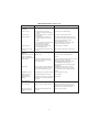
OWNERS MANUAL
INSTALLATION AND OPERATING INSTRUCTIONS
4” SUBMERSIBLE PUMPS
90 GPM
Single and Three Phase
2 through 10 HP – 60 Hz
Single and Three Phase
1-1/2 through 7-1/2 HP – 50 Hz
Record the following information from the motor and
pump nameplates for future reference:
Pump Model No.
Pump Serial No.
Motor Model No.
Motor Serial No.
H.P.
Volts/Hz/Ph
Rated Amp Draw
STA-RITE INDUSTRIES, INC.,
DELAVAN, WISCONSIN 53115
Printed in U.S.A. ©2003, Sta-Rite Industries, Inc.
S689 (Rev. 6/30/03)
Carefully read and follow all safety instructions
in this manual or on pump.
This is the safety-alert. When you see
this symbol on your pump or in this manual, look for one of the following signal words
and be alert to the potential for personal injury.
5. During installation, keep well covered as
much as possible to prevent leaves and foreign
matter from falling into well. Foreign objects
in well can contaminate the water and cause
serious mechanical damage to the pump.
6. Pipe joint compound can cause cracking in
plastics. Use only teflon tape when sealing
joints in plastic pipe or connecting pipe to
thermoplastic pumps.
warns about hazards that will
cause serious personal injury, death or major
property damage if ignored.
TABLE OF CONTENTS
warns about hazards that can
cause serious personal injury, death or major
property damage if ignored.
Safety Instructions . . . . . . . . . . . . . . . . . . . . .2
Pre-Installation . . . . . . . . . . . . . . . . . . . . . . .2
Electrical-General . . . . . . . . . . . . . .2-3, 11-12
60 Hz Fuse, Wire, Motor Specs. . . . . . . . .4-6
50 Hz Fuse, Wire, Motor Specs. . . . . . . .7-10
Wiring Diagrams . . . . . . . . . . . . . . . . . .10-15
Installation . . . . . . . . . . . . . . . . . . . . . . .16-17
Initial Startup . . . . . . . . . . . . . . . . . . . . .17-18
Connecting to Tank/Water System . . . . . .18-21
Troubleshooting Guide . . . . . . . . . . . . . .22-23
Warranty . . . . . . . . . . . . . . . . . . . . . . . . . . .24
warns about hazards that will or
can cause minor personal injury or property
damage if ignored.
The word NOTICE indicates special instructions
which are important but not related to hazards.
To avoid serious or fatal personal injury and
possible property damage, carefully read and
follow the safety instructions.
1.
Hazardous pressure. Under
certain conditions, submersible pumps can
develop extremely high pressure. Install a
pressure relief valve capable of passing entire
pump flow at 75 PSI (517 kPa) when using an
air over water pressure tank. Install a pressure relief valve capable of passing entire
pump flow at 100 PSI (690 kPa) when using a
pre-charged pressure tank.
PRE-INSTALLATION
Inspect pump and motor for delivery damage.
Report any damage immediately to the shipping
carrier or to your dealer.
The well driller should thoroughly develop the
well (that is, pump out all fine sand and foreign
matter) before pump is installed.
Pump performance is based on pumping clear,
cold, liquid water.
Warranty is void in the following conditions:
• If pump has pumped excessive sand – excessive sand can cause premature wear to pump.
• If water is corrosive.
• If entrained gas or air are present in the water
being pumped – these can reduce flow and
cause cavitation which can damage pump.
• If pump has been operated with discharge
valve closed – severe internal damage will
result.
Install pump at least 15 to 20' (4.5 to 6M) below
the lowest water level reached with pump running (lowest draw-down water level), and at
least 5' (1.5M) above the bottom of the well.
Do not allow pump, pressure tank,
piping, or any other system component
containing water to freeze. Freezing may
damage system, leading to injury or flooding. Allowing pump or system components
to freeze will void warranty.
2.
Hazardous voltage. Can shock,
burn or cause death. To avoid dangerous or
fatal electric shock hazard, use pump only in
a water well.
Installation must meet United States
National Electrical Code, Canadian Electrical
Code, and local codes (as applicable) for all
wiring.
Disconnect electrical power supply
before installing or servicing pump.
WIRING/GROUNDING:
Hazardous voltage. Can shock,
burn, or cause death. Permanently ground
pump, motor and control box before connecting power supply to motor.
Ground pump and motor in accordance with the
local codes and ordinances. Use a copper
ground wire at least as large as wires carrying
current to motor.
Make sure line voltage and frequency of
power supply match motor nameplate voltage
and frequency.
3. Install pump according to all plumbing, pump
and well code requirements.
4. Test well water for purity before using well.
Call your local health department for testing
procedure.
2
wrong direction. Interchange any two cable
leads where they connect to the “lead” terminals
in the magnetic starter. With connections properly made, and pump lowered into water, turn on
the switch again and the pump should deliver
water according to the performance charts.
Motor is supplied with a copper ground wire.
Splice this ground wire to a copper conductor
that matches motor wire size specified in
Table V. See Pages 16 and 17 for cable splicing
instructions.
Permanently ground pump, motor and control
box before connecting power cable to power
supply. Connect ground wire to approved
ground first and then connect to equipment
being installed.
Do not ground to a gas supply line.
OVERLOAD PROTECTION OF THREE
PHASE SUBMERSIBLE MOTORS –
CLASS 10 PROTECTION REQUIRED
The characteristics of submersible motors are
different from standard motors and special overload protection is required.
If the motor is stalled, the overload must trip
within 10 seconds to protect the motor windings. The installer must use SUBTROL or the
quick-trip protection shown in Table I. All recommended overload selections are of the ambient compensated type to maintain protection at
high and low air temperatures.
All heaters and amp settings shown are based on
total line amps. When a six-lead motor is used
with a Wye-Delta starter, divide motor amps by
1.732 to make your selection or adjustment for
heaters carrying phase amps.
Tables I and V list the correct selection and settings for several manufacturers. Approval of
other types may be requested from the motor
manufacturer.
NOTICE: Warranty on three phase submersible
motors is void unless proper quick trip protection in all three motor lines is used.
Fire and electrical shock hazard. If
using a drop cable larger than No. 10 (5.5mm2)
(for example, No. 8 (8.4mm2) wire) between
pump and control box, run cable to a separate
junction box. Connect junction box to control
box with a No. 10 (5.5mm2) or smaller wire
(depending on amp rating of pump – see Table
II, III, or IV).
For more information, contact your local code
officials.
WIRING CONNECTIONS:
Installation must meet United States National
Electrical Code, Canadian Electrical Code and
local codes for all wiring (as applicable).
Use only copper wire when making connections
to pump and control box.
To avoid over-heating wire and excessive voltage
drop at motor, be sure that wire size is at least as
large as size listed in Table V for your horsepower pump and length of wire run.
NOTICE: See Pages 11 through 15 for typical
wiring hookups and control box identification.
NOTICE: When built-in overheating protection
is not provided, install an approved overload
equipped motor control that matches motor
input in full load amps. Select or adjust overload
element(s) in accordance with control instructions. When built-in overheating protection is
provided, use an approved motor control that
matches motor input in full load amperes.
SURGE ARRESTERS IN CONTROL BOX
Grounding: When the box has a surge arrester,
the surge arrester MUST be grounded, metal to
metal, all the way to the water strata for the
arrester to be effective. Grounding the arrester
to a driven ground rod provides little or no protection for the motor.
NOTICE: Surge arresters DO NOT protect
against direct lightning strikes.
Install grounded surge arresters to protect pump
from high voltage surges. Install arrester on the
incoming power line to control box or pressure
switch, as close to pump motor as possible. See
Figures 1 and 2 for installation wiring diagrams
for arresters.
NOTICE: Ground the arrester with a No. 10 or
larger bare wire. Ground according to local
code requirements.
NOTICE: If surge arresters wired into the control
box are against local electrical code, contact
power company for correct wiring information.
Rotation – (3 Phase only)
To make sure motor is running in the right direction, proceed carefully as follows:
After electrical connections have been made as
outlined, and with pump hanging in well supported from clamp on the discharge pipe, turn
on then turn off the switch connecting the motor
to the power supply line. Note rotation of pump
as motor starts. If connections are properly
made, pump will “jerk” clockwise when looking
into the pump discharge when started. If “jerk”
is counter-clockwise, the motor is running in the
3
60 Hz. Franklin Motor Electrical Specifications
TABLE I – Overloads for 3 Phase 60 Hertz 4" Franklin Motors
Heaters for
Overload Relays
Adjustable
Relays
(Note 4)
HP
KW
Volts
NEMA
Starter
Size
Set
Max.
2
1.5
230
460
575
0
00
00
K49
K33
K29
J25
J18
J15
L910A
L463A
L380A
7.5
3.8
3.0
8.1
4.1
3.2
3
2.2
230
460
575
0
0
0
K52
K37
K34
J28
J21
J19
L122B
L618A
L510A
10.1
5.1
4.1
10.9
5.5
4.4
5
3.7
230
460
575
1
0
0
K61
K49
K42
J33
J26
J23
L199B
L100B
L825A
16.6
8.3
6.6
17.8
8.9
7.1
7.5
5.5
230
460
575
1
1
1
K67
K55
K52
J37
J30
J28
L293B
L147B
L122B
24.6
12.3
9.9
26.4
13.2
10.6
10
7.5
460
575
1
1
K61
K57
J33
J31
L220B
L181B
17.5
14.0
18.8
15.0
Furnas
(Note 1)
Allen Bradley
(Note 2)
GE
(Note 3)
TABLE I NOTES:
Recommended Adjustable
Overload Relays
NOTE 1: Furnas intermediate sizes between NEMA
starter sizes apply where (1) is shown in tables, size 13/4 replacing 2, 2-1/2 replacing 3, 3-1/2 replacing 4
and 4-1/2 replacing 5. Heaters were selected from
Catalog 294, Table 332 and Table 632 (starter size 00,
size B). Size 4 starters are heater type 4 (JG). Starters
using these heater tables include classes 14, 17 and 18
(INNOVA), classes 36 and 37 (reduced voltage), and
classes 87, 88 and 89 (pump and motor control centers). Overload relay adjustments should be set no
higher than 100% unless necessary to stop nuisance
tripping with measured amps in all lines below nameplate maximum. Heater selections for class 16 starters
(Magnetic Definite Purpose) will be furnished upon
request.
NOTE 2: Allen-Bradley heaters were selected from
Catalog IC-110, Table 162 (through starter size 4), Table
547 (starter size 5), and Table 196 (starter size 6).
Bulletin 505, 509, 520, 540 and 570 use these heater
tables. Heater selections for bulletin 1232X and 1233X
starters will be furnished upon request.
NOTE 3: General Electric heaters are type CR123
usable only on type CR124 overload relays and were
selected from Catalog GEP-126OJ, page 184.
Adjustment should be set no higher than 100%, unless
necessary to stop nuisance tripping with measured
amps in all lines below nameplate maximum.
AEG Series: B17S, B27S, B27-2.
Allen Bradley: Bulletin 193, SMP-Class 10 only.
Fanal Types: K7 or K7D through K400.
Franklin Electric: Subtrol-Plus.
General Electric: CR4G, CR7G, RT*1, RT*2, RTF3, RT*4,
CR324X-Class 10 only.
Klockner-Moeller Types: Z00, Z1, Z4, PKZM1, PKZM3, PKZ2.
Lovato: RC9, RC22, RC80, RF9, RF25, RF95.
Siemens Types: 3UA50, -52, -54, -55, -58, -59, -60, -61, -62,
-66, -68, -70, 3VUI3, 3VE, 3UB (Class 5).
Sprecher and Schuh Types: CT, CT1, CTA 1, CT3K, CT3-12
thru CT3-42, KTA3, CEF1 & CET3 set at 6 sec. max., CEP 7
Class 10, CT4, 6, & 7, CT3.
Square D/Telemecanique: Class 9065 types TD, TE, TF, TG,
TJ, TK, TR, TJE, TJF (Class 10) or LR1-D, LR1-F, LR2-D13,
-D23, -D33, Types 18A, 32A, SS-Class 10, SR-Class 10 and
63-A-LB Series. Integral 18,32,63, GV2-L, GV2-M, GV2-P,
GV3-M (1.6-10 amp only).
Westinghouse Types: FT13, FT23, FT33, FT43, K7D, K27D,
K67D, Advantage (Class 10), MOR, IQ500 (Class 5).
Other relay types from these and other manufacturers
may or may not provide acceptable protection, and
they should not be used without approval of Franklin
Electric.
Some approved types may only be available for part of
the listed motor ratings. When relays are used with current transformers, relay setting is the specified amps
divided by the transformer ratio.
NOTE 4: Adjustable overload relay amp settings apply
to approved types listed. Relay adjustment should be
set at the specified SET amps. Only if tripping occurs
with amps in all lines measured to be within nameplate
maximum amps should the setting be increased, not to
exceed the MAX value shown.
4
60 Hz. Franklin Motor Electrical Specifications
TABLE II – Recommended Fusing Data 60 Hz, Single Phase, 3 Wire Capacitor Run
Submersible Pump Motors
HP
Volts/
Hz/Ph
Surge
Arrester
Control
Box
L1 L2 R Y B
Motor Winding
Max Locked Fuze Size
Resistance-Ohms Load Rotor Standard/
R to Y
B to Y Amps Amps Dual Element
2
230/60/1 5.2-7.15
1.6-2.3
13.2
51.0
30/20
3
230/60/1
3.0-4.9
0.9-1.5
17.0
82.0
45/30
5
230/60/1
2.1-2.8
0.68-1.0 27.5
121.0
80/45
FIGURE 1 – Typical 3 Wire, Single Phase, 230
Volt Surge Arrester
Red to Yellow = start winding resistance;
Black to Yellow = main winding resistance.
HP
Volts/
Hz/Ph
Max Input
Line to
(S.F. Load)
Line
Amps
Resistance
Locked
Rotor
Amps
Fuze Size
Standard/
Dual Element
2
230/60/3
460/60/3
575/60/3
8.1
4.1
3.2
2.4-3.0
9.7-12.0
15.1-18.7
46.6
23.3
18.6
25/15
15/8
10/5
3
230/60/3
460/60/3
575/60/3
10.8
5.4
4.3
1.8-2.2
7.0-8.7
10.9-13.6
61.9
31.0
24.8
30/20
15/10
15/8
5
230/60/3
460/60/3
575/60/3
17.7
8.9
7.1
0.93-1.2
3.6-4.4
5.6-6.9
106.0
53.2
42.6
50/30
25/15
20/15
7-1/2 230/60/3
460/60/3
575/60/3
26.0
13.0
10.4
0.61-0.75
2.4-3.4
3.5-5.1
164.0
81.9
65.5
80/45
40/25
30/20
18.5
14.8
1.8-2.3
2.8-3.5
116.0
92.8
60/45
45/35
10
460/60/3
575/60/3
Line
Surge
Arrester
TABLE III – Recommended Fusing Data 60 Hz, 3 Phase Submersible Pump Motors
L1
T1
L2
L3
T2
T3
FIGURE 2 - Three Phase Surge Arrester (650
Volt Maximum)3 Phase Surge Arrester
(650 Volt Maximum)
5
60 Hz. Franklin Motor Electrical Specifications
TABLE IV – Cable Length in Feet
1 Phase, 3 Wire Cable, 60 Hz. Copper Wire Size AWG (Service to Motor)
Volts
HP
14
12
10
8
6
4
3
2
1
0
230V
2
3
150
120*
250
190
390
300
620
470
970
750
1530
1190
1910
1490
2360
1850
2390
2320
3620
2890
5
–
–
180
280
450
710
890
1110
1390
1740
3 Phase, 3 Wire Cable, 60 Hz.
Volts
230V
460V
575V
HP
14
12
10
8
6
4
3
2
1
0
2
3
320
240
510
390
810
620
1280
990
2010
1540
3130
2400
3890
2980
4770
3660
5860
4480
7170
5470
5
7-1/2
10
140*
–
–
230
160*
–
370
260
190*
590
420
310
920
650
490
1430
1020
760
1790
1270
950
2190
1560
1170
2690
1920
1440
3290
2340
1760
2
3
1300
1000
2070
1600
3270
2520
5150
3970
8050
6200
–
–
–
–
–
–
–
–
–
–
5
7-1/2
590
420
950
680
1500
1070
2360
1690
3700
2640
5750
4100
–
5100
–
6260
–
7680
–
–
10
310
500
790
1250
1960
3050
3800
4650
5750
7050
2
3
5
2030
1580
920
3250
2530
1480
5110
3980
2330
8060
6270
3680
–
–
5750
–
–
–
–
–
–
–
–
–
–
–
–
–
–
–
7-1/2
10
660
490
1060
780
1680
1240
2650
1950
4150
3060
–
4770
–
5940
–
–
–
–
–
–
*Meets NEC for individual conductor 60°C cable. Only length without * meet NEC for jacketed 60°C cable.
Local code requirements may vary.
TABLE IV NOTES:
1. Maximum cable lengths shown maintain
motor voltage at 95% of service entrance
voltage, running at maximum nameplate
amperes. If service entrance voltage will be at
least motor nameplate voltage under normal
load conditions, 50% additional length is permissable for all sizes.
2. Sizes given are for copper wire. For aluminum wire, go two sizes larger. For example, if table lists #12 (3mm2) copper wire, use
#10 (5mm2) aluminum wire.
3. For reliable 3 Phase starter operation, length
of wire between starter and service entrance
should be not more than 25% of total wire
length.
6
50 Hz. Franklin Motor Electrical Specifications
TABLE V – Overloads for 3 Phase 50 Hertz 4" Franklin Electric Motors
Heaters for
Overload Relays
Adjustable
Relays
(Note 3)
HP
KW
Volts
NEMA
Starter
Size
Set
Max.
1.5
1.1
220
380/415
00
00
K37
K28
J20
J14
L561A
L343A
4.09
2.67
5.1
2.9
2
1.5
220
380/415
0
00
K41
K32
J23
J17
L750A
L420A
6.07
3.50
6.6
3.8
3
2.2
220
380/415
0
0
K52
K37
J26
J22
L111B
L618A
8.74
5.06
9.5
5.5
5
3.7
220
380/415
1
0
K57
K49
J31
J26
L181B
L100B
14.2
8.19
15.4
8.9
7.5
5.5
220
380/415
1
1
K63
K55
J35
J30
L265B
L147B
21.0
12.1
22.8
13.2
Furnas
(Note 1)
Allen
Bradley
GE
(Note 2)
TABLE V NOTES:
Approved relays include:
AEG Series: B175, B27S 11-17A and
15-23A, B27-2 11-17A and 15-23A.
ASEA Type: RVH40.
Allen Bradley: Bulletin 193.
Fanal Types: K7 or K7D through K400.
NOTE 1: Heaters listed apply to Innova 45
designs and Definite Purpose Class 16 starters
through their available range, and to standard
starters in larger sizes. Set overload relay adjustments no higher than 100%, unless necessary to
stop nuisance tripping with measured amps in
all lines below nameplate maximum.
NOTE 2: General Electric heaters are type
CR123 usable only on type CR124 overload
relays. Adjustment should be set no higher than
100%, unless necessary to stop nuisance tripping with measured amps in all lines below
nameplate maximum.
NOTE 3: Adjustable overload relay amp settings
apply to approved types listed below. Request
approval of other types from Franklin Electric.
Set relay adjustment at specified SET amps; do
not increase setting unless motor trips with measured amps in all lines within nameplate maximum amps. Do not increase setting past MAX
value shown. Some approved types may not be
available for all listed motor ratings. When using
relays with current transformers, set relay to
specified amps divided by transformer ratio.
General Electric: CR4G1T-, CR4G1W-,
CR4G2W-, CR4G3W-.
Klockner-Moeller Types: Z00, Z1, Z4, PKZM3.
Lovato: RC-22 to RC-80.
RTE Delta Types: DQ, LR1-D, LR1-F.
Sprecher and Schuh Types: CT, CT1, CTA1.
Siemens Types: 3UA50, -52, -54, -58, -59,
-62.
Square D Class 9065 Types: TUP, MR, TD, TE,
TF, TR, TJE.
Telemecanique Type: LR1-D, LR1-F.
Westinghouse Types: FT13, FT23, FT33, FT43,
K7D, K27D, K67D
Westmaster: OLWR00 and OLWT00, suffix D
through P.
Other relay types from these and other manufacturers should not be used without approval of
Franklin Electric.
7
50 Hz. Franklin Motor Electrical Specifications
TABLE VI – Recommended Fusing Data 50 Hz, Single Phase, 3 Wire Capacitor Run Submersible Pump Motors
Max Input
(S.F. Load)
Amps
Watts
Line to Line
Resistance
M = Main
S = Start
Locked
Rotor
Amps
KW
HP
Volts/
Hz/Ph
Fuze Size
Standard
Dual Element
1.1
1.5
220/50/1
Y 9.7
B 9.6
R 1.0
1690
2.4-2.9 M
6.4-7.8 S
40.6
20
9
1.5
2
220/50/1
Y 11.2
B 10.6
R 2.0
2160
2.0-2.5 M
8.0-9.7 S
54.3
30
15
2.2
3
220/50/1
Y 17.3
B 16.7
R 3.5
3270
1.1-1.4 M
3.7-4.5 S
87.5
50
25
3.7
5
220/50/1
Y 25.5
B 22.4
R 7.7
5150
.79-.97 M
2.4-2.9 S
118.0
70
30
TABLE VII – Recommended Fusing Data - 50 Hz, 3 Phase Submersible Pump Motors
Volts/
Hz/Ph
Max Input
(S.F. Load)
Amps
Watts
Line to Line
Resistance
Locked
Rotor
Amps
Fuze Size
Standard
Dual Element
KW
HP
1.1
1.5
220/50/3
380/50/3
415/50/3
5.1
3.1
2.9
1600
1510
1540
5.9-7.2
12.1-14.7
12.1-14.7
20.8
15.5
16.9
15
15
15
6.0
3.5
3.5
1.5
2
220/50/3
380/50/3
415/50/3
6.6
3.8
3.8
2120
2120
2080
3.0-3.7
9.1-11.1
9.1-11.1
35.8
20.7
22.6
20
15
15
8.0
4.5
4.5
2.2
3
220/50/3
380/50/3
415/50/3
9.5
5.5
5.6
3100
3100
3080
2.4-2.9
7.2-8.8
7.2-8.8
46.7
27.0
29.5
25
15
15
12
7
7
3.7
5
220/50/3
380/50/3
415/50/3
15.4
8.9
9.0
5030
5030
5100
1.3-1.6
4.0-4.9
4.0-4.9
79.6
46.1
50.4
40
25
25
20
10
10
5.5
7.5
220/50/3
380/50/3
415/50/3
22.8
13.2
13.4
7430
7430
7450
0.84-1.0
2.5-3.1
2.5-3.1
120.0
69.5
75.9
60
35
35
30
15
15
NOTE:
1. Maximum cable lengths shown maintain
motor voltage at 95% of service entrance
voltage, running at maximum nameplate
amperes. If service entrance voltage will be
at least motor nameplate voltage under normal load conditions, 50% additional length
is permissable for all sizes.
2. Sizes given are for copper wire. For aluminum wire, go two sizes larger. For example, if table lists #12 (3mm2) copper wire,
use #10 (5mm2) aluminum wire.
3. For reliable 3 Phase starter operation, length
of wire between starter and service entrance
should be not more than 25% of total wire
length.
8
50 Hz. Franklin Motor Electrical Specifications
TABLE VIII – Maximum Cable Length in Feet (AWG Wire) or Meters (mm2 Wire)
1 Phase, 3 Wire Cable, 50 Hz. Copper Wire Size (Service to Motor)
Motor Rating
AWG-Feet
mm2 - Meters
KW
Volts
HP
14
12
10
8
6
1.5
2.5
4
6
10
1.1
1.5
2.2
3.7
220
220
220
220
1-1/2
2
3
5
220
170
110
0
360
280
180
0
570
440
280
190
900
690
440
300
1410
1090
700
480
40
30
20
0
70
60
40
20
120
90
60
40
180
130
90
60
300
230
150
100
14
12
AWG-Feet
10
8
6
1.5
2.5
mm2 - Meters
4
6
10
480
370
250
150
770
600
410
250
1220
940
650
390
1940
1500
1030
620
3040
2350
1610
980
90
70
50
30
160
120
80
50
250
190
130
80
380
290
200
120
650
500
340
210
3 Phase, 3 Wire Cable, 60 Hz.
KW
Motor Rating
Volts
HP
1.1
1.5
2.2
3.7
220
220
220
220
1-1/2
2
3
5
5.5
220
7-1/2
0
170
280
440
700
0
30
60
90
150
1.1
380
1-1/2
1550
2480
3910
6170
9650
300
500
810
1210
2060
1.5
380
2
1130
1810
2850
4510
7060
220
370
590
880
1500
2.2
380
3
770
1230
1950
3080
4830
150
250
400
600
1030
3.7
380
5
470
750
1190
1880
2950
90
150
240
370
630
5.5
380
7-1/2
330
530
840
1330
2090
60
110
170
260
440
NOTE: for 415 Volt hookup, use 115% of 380 Volt table ratings.
9
Calculating Cable size when two different
sizes can be used.
Calculating Cable size when two different
sizes can be used.
Sometimes conditions make it desirable to use
more than one size cable in an installation.
For example: Replace a pump with a 3 HP, 230
volt, 60 Hz, single phase motor, with the motor
setting at 310' down the well and with 160' of
#10 cable buried between the service entrance
and the well head. In order to avoid replacing the
buried cable, the question is: What size cable is
required in the well? Calculate as follows:
1. According to Table IV, a total of 300' of #10
cable is allowed to power the 3 HP motor.
The per cent of this total that has been used
by the 160' of cable in the buried run is:
160'/300' = .533 = 53.3%.
160 Ft. AWG 10
(53.3% of Allowable Cable)
310 Ft. AWG 6
Cable
Service Entrance
(Main Fuse Box
From Meter)
Service Entrance
(Main Fuse Box
From Meter)
Pump
Controls
3 HP (2.2 kw)
230V 1Ph Motor
(41.3% of
Allowable
Cable)
218 0993
Example (Metric): When replacing pump motor
in an installation already having 55M of buried
10 mm2 cable between service entrance and well
head, what size cable is required in the well
(from well head to motor) when using a 3 HP
(2.2kw), 220 volt, 50 Hz, single phase motor set
125M below the well head?
160 Ft. AWG 10
(53.3% of Allowable Cable)
Cable
Pump
Controls
3 HP (2.2 kw)
230V 1Ph Motor
310 Ft. AWG 6
Solution (Metric): According to Table VIII, 150 M
is the maximum allowable length when using 10
mm2 cable with a 3 HP (2.2kw) 1ø motor. The
installation has 55 M already in place.
218 0993
55 M (used) ÷ 150 M (allowed) = 36%.
Approximately 36% of allowable cable has been
used. That leaves approximately 64% of allowable cable still available for use in the well.
(41.3% of
Allowable
Cable)
2. With 53.3% of the allowable cable already
used, 46.7% of the total length is left for use
in the well. To avoid running a cable that is
too long and lowering the voltage to the
motor, we have to find a cable size large
enough so that 310' is less than 46.7% of the
total length allowed for that size.
3. Trying #8 cable, Table IV shows that the total
allowable length for a 3 HP motor is 470'.
470' x 46.7% = 470' x .467 = 219.5'
This is not long enough.
4. Trying #6 cable, Table IV shows that the total
allowable length is 750'.
750' x 46.7% = 750' x .467 = 350.25'
This is longer than needed. Therefore, #6
cable can be used for the 310' of cable in the
well.
Any combination of sizes can be used, provided that the total percentage of the length
of the two sizes of cable does not exceed
100% of the allowed lengths.
According to Table VIII, 16 mm2 cable can be
used to a maximum of 230 M. 64% of 230 M =
147 M; this is more than the length required,
therefore 16 mm2 wire can be used.
NOTICE: When figuring the percent of cable
length of any size that can be used, remember
that the total percentages of all sizes cannot add
to more than 100%.
10
INSTALLATION WIRING DIAGRAMS SINGLE PHASE, 3 WIRE
LIQUID LEVEL (PUMP DOWN)
CONTROLS:
For motors of 1-1/2 HP and
above, use magnetic starter to avoid damage to
pressure switch. Consult factory for wiring
information.
Use pump down controls on wells with low flow
to prevent pumping well dry. See Wiring diagrams,
Pages 12 through 15, for proper installation.
NOTICE: Ground controls according to local
code requirements.
Hazardous voltage. Can shock,
burn, or kill.
Ground control box, all metal plumbing, and
motor frame with copper wire in compliance
with local codes. Use a ground wire at least as
large as the wires supplying power to motor.
Permanently close all unused openings in this
and other equipment.
Disconnect power to control box before working on or around control box, pipes, cable,
pump, or motor.
To be sure that starting relay will function and
that overload will not “nuisance trip”, install
control box vertically with top side up.
Wire control box as shown on Pages 12 through
14. Pump will not operate without control box,
and deluxe boxes require a switch or a jumper
lead between ‘SW’ and ‘L2’ terminals. Operation
without control box will burn out motor.
Installation must meet United States National
Electrical Code, Canadian Electrical Code, and
local codes for all wiring (as applicable).
If main overload trips, look for:
1. Shorted Capacitor
2. Voltage Problems
3. Overloaded or locked pump.
NOTICE: Match motor to control box as shown
below. Franklin motor and control box model
numbers may include additional suffix numbers
to the right of the numbers shown here. These
additional numbers are not important for control
box selection.
TABLE IX: Control Box Selection
HP
Voltage
Motor
No.
Control
Box No.
2
230
224301
28230181
28230183
3
230
224302
28230281
28230283
5
230
224303
28211381
28211383
If start overload trips, replace start relay. Reset
and analyze for tripping cause. To avoid motor
burnout, do not remove or short circuit overload
protection.
11
CHECKING PROCEDURE (ALL BOXES):
C. Capacitor Tests. (Power to control box disconnected)
Hazardous voltage. Can shock,
burn, or cause death. Disconnect power to control box before doing these check procedures.
Risk of electric shock. Short
capacitor across terminals before testing.
1. Ohmmeter Setting: Rx1000.
2. Terminal Connections: Connect ohmmeter
leads to black and orange wires out of
capacitor case.
3. Ohmmeter Reading: Pointer should swing
toward “zero” and “float” back to (!).
Capacitor is shorted if pointer does not
move back to (!), open if it does not move
from (!).
4. To reset capacitor, reverse ohmmeter connection to capacitor terminals.
A. General Procedures. (Power to control box
disconnected)
1. Disconnect line.
2. Inspect for damaged or burned parts, loose
connections, etc.
3. Check for misconnections against diagram
in control box.
4. If box is too hot, circuit breakers may trip
or fuses blow. Ventilate or shade box.
Move away from heat source.
5. If problem has not been found, check
motor and control box. Use test procedures that follow.
D.Triac Test. (Solid state switch only)
1. Ohmmeter Setting: Rx1000.
2. Connect the leads to “R” (start) terminal
and to orange lead terminal on start
switch.
3. Ohmmeter reading: Infinity (!).
B. Ground (Insulation Resistance) Test. (Power
to control box disconnected)
1. Ohmmeter Setting: Highest scale (usually
Rx100K or Rx10,000).
2. Terminal Connections: One ohmmeter lead
to “Ground” screw on control box and
touch other lead to each of the terminals
on terminal board.
3. Ohmmeter Reading: Pointer should remain
at infinity (!) and not deflect.
E. Coil Test. (Solid state switch only)
1. Ohmmeter Setting: Rx1.
2. Connect leads to “Y” (common) and L2 terminal and to orange lead terminal on start
switch.
3. Ohmmeter reading: Infinity (!).
Installation Wiring Diagrams – Single Phase, 3 Wire
For motors of 1-1/2 HP and above, use magnetic starter to avoid damage to pressure
switch. Consult factory for wiring information.
SINGLE PHASE - 1/2 HP THRU 5 HP STANDARD
CONTROL BOX WITH ADEQUATE RATED
PRESSURE SWITCH
SINGLE PHASE - 1/2 HP THRU 5 HP STANDARD
CONTROL BOX WITH PRESSURE SWITCH (One pump
for 2 houses) With adequate rated pressure switch
Ground
To Line
To Line
CONTROL
BOX
Pressure
Switch
L1 L2 R Y B
L1
M1
L2
M2
Fused
Disconnect
Switch
Ground
To Line
Fused
Disconnect
Switch
Pressure
Switch
L1
M1
L2
M2
Pressure
Switch
M1
L2
M2
CONTROL
BOX
Aux. Relay
or Equivalent
Red
Yellow
Black
L1
L1 L2 R Y B
Red
Yellow
Black
Ground
Well
Casing
Ground
355 0893
Well
Casing
359 0893
Follow color coding when connecting control box (Yellow to Y, Red to R, Black to B).
12
Installation Wiring Diagrams – Single Phase, 3 Wire
For motors of 1-1/2 HP and above, use magnetic starter to avoid damage to pressure
switch. Consult factory for wiring information.
SINGLE PHASE - 1/2 HP THRU 5 HP STANDARD
CONTROL BOX WITH LIQUID LEVEL CONTROL
To Line
SINGLE PHASE - 1/2 HP THRU 5 HP STANDARD
CONTROL BOX WITH PRESSURE SWITCH &
LIQUID LEVEL CONTROL
Ground
To Line
Ground
Pressure
Switch
Fused
Disconnect
Switch
Fused
Disconnect
Switch
Control
Box
L1
L1 L2 R Y B
Liquid
Level
Control
L2 M2
1
8
2
9
6
1
8
7
2
9
5
Low
Electrode
L1 L2 Y B R
BW Liquid
Level Control
5
High
Electrode
Control
Box
M1
Red
Yellow
Black
Ground
Low
Electrode
353 0893
7
Yellow
Black
Red
High
Electrode
Well
Casing
6
Well
Casing
1271 0994
OPEN SYSTEM-SINGLE PHASE - 1/2 HP THRU 5 HP
STANDARD CONTROL BOX
To Line
Ground
Control
Box
L1 L2 R Y B
Fused
Disconnect
Switch
Red
Yellow
Black
Well
Casing
Ground
357 0893
Follow color coding when connecting control box (Yellow to Y, Red to R, Black to B).
13
Ground
Installation Wiring Diagrams – Single Phase and Three Phase
For motors of 1-1/2 HP and above, use magnetic starter to avoid damage to pressure
switch. Consult factory for wiring information.
SINGLE PHASE - 2, 3 & 5 HP DELUXE CONTROL
BOXES WITH LIQUID LEVEL CONTROL
SINGLE PHASE - 2, 3 & 5 HP DELUXE CONTROL
BOXES WITH PRESSURE SWITCH
To Line
Ground
Ground
To Line
Fused
Disconnect
Switch
Fused
Disconnect
Switch
Control
Box
Control
Box
SW L1 L2 Y B R
BW Liquid
Level Control
L1
Pressure
Switch
SW L1 L2 Y B R
M1
L2 M2
1
8
6
2
9
7
5
Yellow
Black
Red
Yellow
Black
Red
High
Electrode
Well
Casing
Ground
3108 1197
Low
Electrode
Ground
Well
Casing
354 0893
SINGLE PHASE - 2, 3 & 5 HP DELUXE CONTROL
BOXES WITH PRESSURE SWITCH &
LIQUID LEVEL CONTROL
To Line
SINGLE PHASE - 2, 3 & 5 HP DELUXE CONTROL
BOXES OPEN SYSTEM
To Line
Ground
Pressure
Switch
Fused
Disconnect
Switch
Fused
Disconnect
Switch
L1
Ground
Control
Box
Control
Box
M1
SW L1 L2 Y B R
SW L1 L2 Y B R
L2 M2
BW Liquid
Level Control
1
8
2
9
5
High
Electrode
Low
Electrode
6
7
Yellow
Black
Red
Yellow
Black
Red
Well
Casing
Well
Casing
Ground
1270 0994
358 0893
Follow color coding when connecting control box (Yellow to Y, Red to R, Black to B).
14
Ground
Installation Wiring Diagrams – Three Phase
THREE PHASE - 1-1/2 HP & LARGER
WITH PRESSURE SWITCH
THREE PHASE - 1-1/2 HP & LARGER
WITH PRESSURE SWITCH &
LIQUID LEVEL CONTROL
Pressure
Switch
M
L
M
L
Pressure
Switch
M
L
M
L
Fused
Disconnect
Switch
Magnetic
Starter
Fused
Disconnect
Switch
L1
L2
L3
Magnetic
Starter
1
8
2
9
5
Liquid
Level
Control
T1
T2
L1
L2
L3
T1
T2
T3
6
7
T3
High
Electrode
Low
Electrode
Well
Casing
361 0893
Well
Casing
362 0893
Follow color coding when connecting control box (Yellow to Y, Red to R, Black to B).
15
Installation
6. Cut “Scotchfil” electrical insulation putty
into 3 equal parts and form tightly
around butt connectors. Be sure scotchfil overlaps insulated part of wire.
7. Using #33 Scotch tape, wrap each joint
tightly; cover wire for about 1-1/2"
(38mm) on each side of joint. Make four
passes with the tape. In other words,
when finished you should have four layers of tape tightly wrapped around the
wire. Press edges of tape firmly down
against the wire (see Figure 8).
NOTICE: Since the tightly wound tape is
the only means of keeping water out of
the splice, the efficiency of the splice
will depend on the care used in wrapping the tape.
NOTICE: For wire sizes larger than #8,
(8.4mm2) use a soldered joint rather than
Scotchfil putty (see Figure 6).
B. Heat-shrink splice (For wire sizes #14, 12
and 10 AWG, or 2, 3, and 5.5mm2):
1. Remove 3/8" (10mm) insulation from
ends of motor leads and drop cable
wires.
2. Put plastic heat shrink tubing over motor
leads.
3. Match wire colors and lengths in drop
cable to wire colors and lengths of
motor leads.
4. Insert cable and motor wire ends into
butt connectors and crimp (See Figures
4 and 5). BE SURE to match wire colors
between drop cable and motor leads.
Pull leads to check connections.
5. Center tubing over butt connector and
apply heat evenly with a torch (a match
or lighter will not supply enough heat).
CABLE SPLICING:
1. Splice cable to motor leads. Use one of the
three methods outlined below. Use only copper wire for connections to pump motor and
control box.
A. Taped splice (Wire sizes No. 8 (8.4mm2)
and larger):
1. Cut off motor leads. Stagger lead and
wire length so that 2nd lead is 2"
(50mm) longer than 1st lead and 3rd
lead is 2" (50mm) longer than second.
2. Cut off cable ends. Be sure to match
colors and lengths of wires in drop cable
to colors and lengths of motor leads.
3. Trim insulation back 1/2" (13mm) from
cable ends and motor lead ends.
4. Insert motor lead ends and cable ends
into butt connectors (see Figure 4). Be
sure to match wire colors between drop
cable and motor leads.
5. Using crimping pliers (Figure 7), indent
butt connector lugs (see Figure 5) to
attach wires.
1/2"
(12.7mm)
BUTT CONNECTOR
FIGURE 4
INDENT HERE
FIGURE 5
ALTERNATE METHOD
TWIST AND SOLDER
FIGURE 6
NOTCH
END CAP
1"
2
INSULATOR BODY
1"
2
12.7mm 12.7mm
GASKET
FIGURE 10
FIGURE 7
BUTT CONNECTOR OR
CRIMP OR SOLDER
FIGURE 11
FIGURE 8
COMPLETED SPLICE
CAP SCREWED ON
CONNECTOR
GASKET SLEEVE IN PLACE
FIGURE 12
HEAT SHRINK TUBING
FIGURE 9
16
INSULATOR BODY
CENTERED OVER SPLICE
PUMP INSTALLATION
NOTICE: Keep torch moving. Too much
concentrated heat may damage tubing
(see Figure 9).
C. Butt Connectors with plastic insulators (for
14, 12 and 10 Gauge AWG Wire, or 2, 3
and 5.5mm2 wire):
1. Cut off motor leads. Stagger lead and
wire length so that 2nd lead is 4"
(100mm) longer than 1st lead and 3rd
lead is 4" (100mm) longer than second.
2. Cut off cable ends. Be sure to match
colors and lengths of wires in drop cable
to colors and lengths of motor leads.
3. Trim insulation back 1/2" (13mm) from
cable ends and motor lead ends.
4. Unscrew plastic caps from insulators.
Place a cap and a neoprene gasket
sleeve on each wire end to be spliced
(see Figure 10).
5. Slide insulator body onto one wire end
(Figure 10).
6. Insert wire end into butt connector and
crimp (see Figure 11). Be sure to match
cable and motor wire colors.
7. Center insulator body over splice and
slide neoprene sleeves into body as far
as they will go. Screw caps onto insulator body (Figure 12) and tighten by hand
for a strong, waterproof splice.
1. If a standard air over water pressure tank is
being used, install two bleeder orifices about
2' (.6M) apart as shown in Figure 15, Page
21. These orifices will automatically charge
the tank with air. See Figure 15 to determine
orifice location.
NOTICE: If Pre-charged tank is used, DO
NOT install bleeder orifices. If pump and precharged tank are replacing a standard tank
system, remove bleeder orifices before
installing pump in well.
2. To prevent losing pump down the well, connect a safety rope strong enough to support
pump and drop pipe (minimum 5/16" (8mm)
twisted polypropylene or pronila rope) to eyelet on pump discharge. Tie off other end of
safety rope securely to well seal, well cap or
pitless adapter.
3. Discharge outlet is threaded 2” NPT (60 Hz)
or 2” BSP (50 Hz).
Use 100 PSI rated polyethylene plastic pipe
for installations up to 100’ depth.
Use 160 PSI rated polyethylene plastic pipe
for installation up to 220’ depth.
For depths beyond 220’, use galvanized steel
pipe for the entire drop pipe.
INITIAL START-UP
NOTICE: NEVER operate pump with discharge
valve completely closed. Pump can destroy itself
if run with discharge shut off (“deadheaded”) and
warranty will be void.
NOTICE: To avoid sand-locking pump, follow
procedure below when starting pump for the
first time. NEVER start a pump with discharge
completely open unless you have done this procedure first.
1. Connect a pipe elbow, a short length of pipe
and a gate valve to pump discharge at well
head (see Figure 13).
2. Mount motor control box (3-wire pump),
fused disconnect switch (2-wire pump), or
magnetic starter (3-phase pump) in a permanently weather proofed place. Make sure that
controls will not be subjected to extreme heat
or excess moisture.
3. Make sure controls are in OFF position.
4. Connect motor leads and power supply to
motor control box, fused disconnect switch, or
magnetic starter (see Wiring Diagrams, Pages 8
through 12). DO NOT START PUMP YET.
5. Set gate valve on discharge 1/3 open; start
pump (see Figure 13).
6. Keep gate valve at this setting while water
pumps out on ground. Let it run until water is
clear of sand or silt. (To check solids in water,
fill a glass from pump and let solids settle out).
CABLE INSTALLATION
1. To test submersible, momentarily connect it
to proper power supply. Power supply frequency and voltage must match motor nameplate frequency and voltage to within ±10%.
(3 Phase pumps – see “Rotation,” Page 3).
2. Fasten cable leads securely to pump discharge section; leave 4-5" (100-127mm) of
slack in leads at this point. Securely fasten
leads to plastic pipe within 6" (150mm) of the
pump discharge section. Use torque arresters
to protect pump and pipe from twisting damage as pump starts and stops.
3. Connect copper ground wire to motor bracket. Ground wire must be at least as large as
wires supplying current to motor. Consult current National Electrical Code, Canadian
Electrical Code and local codes (as applicable) for grounding information.
4. Use only submersible cable supplied by pump
manufacturer. When lowering pump into well,
secure cable to discharge pipe at 10' (3.5M)
intervals with Scotch #33 electrical tape. Take
care not to damage pump cable.
NOTICE: To avoid dropping the pump down
the well or damaging cable or cable splices,
NEVER allow pump cable to support weight
of pump.
17
Standard Tank Hookup:
7. When water is completely clear at 1/3 setting, open gate valve to approximately twothirds open and repeat process.
8. When water is completely clear at 2/3 setting, open gate valve completely and run
pump until water is completely clear.
9. Remove gate valve for permanent installation
near tank (see Figures 14 and 15, Pages 20
and 21).
10. Install sanitary well seal or pitless adapter
unit, well unit, electrical conduit and surface
piping according to local code requirements.
See Figure 15, Page 21 for piping connections
to standard pressure tank and for correct distance of bleeder orifices from pressure tank.
Pre-charged Pressure Tank Hookup:
See Figure 14, Page 20 for piping connections
to pre-charged pressure tank.
NOTICE: Check air pre-charge in tank before
starting pump. Adjust pre-charge to 2 PSI (13.8
kPa) below pump cut-in setting. (For example, a
pre-charge tank used with a 30-50 switch
should be pre-charged with air to 28 PSI (193
kPa) . Adjust pre-charge by either adding or
bleeding air through tire valve located on top of
tank. Check pre-charge annually and adjust as
needed.
CONNECTING TO TANK/WATER SYSTEM
Hazardous pressure. Submersible
pumps can develop very high pressure in some
situations. To prevent tank blowup, install a
pressure relief valve able to pass full pump flow
at 75 PSI (517 kPa) when using an air over
water pressure tank. Install a pressure relief
valve capable of passing entire pump flow at
100 PSI (690 kPa) when using a pre-charged
pressure tank. Install this relief valve between
pump and tank.
NOTICE: Allowing pump or piping system to
freeze may severely damage pump and will void
warranty. Protect pump and entire piping system
(including pressure tank) from freezing.
Control
center
or
electrical
disconnect
box
Important Electrical
Grounding Information
Hazardous voltage. Can shock,
burn, or kill. To reduce the risk of electrical
shock during pump operation, ground and
bond the pump and motor as follows:
A. To reduce risk of electrical shock from metal
parts of the assembly other than the pump,
bond together all metal parts accessible at the
well head (including metal discharge pipe,
metal well casing, and the like). Use a metal
bonding conductor at least as large as the
power cable conductors running down the well
to the pump's motor.
B. Clamp or weld (or both if necessary) this
bonding conductor to the grounding means
provided with the pump, which will be the
equipment-grounding terminal, the grounding
conductor on the pump housing, or an equipment-grounding lead. The equipment-grounding lead, when provided, will be the conductor
having green insulation; it may also have one
or more yellow stripes.
C. Ground the pump, motor, and any metallic
conduit that carries power cable conductors.
Ground these back to the service by connecting a copper conductor from the pump, motor,
and conduit to the grounding screw provided
within the supply-connection box wiring compartment. This conductor must be at least as
large as the circuit conductors supplying the
pump
Temporary wiring
to control center or
electrical disconnect box
Temporary piping
Gate valve
Pump installation
for developing a well
Pump in well
689 0993
FIGURE 13
Save these instructions.
18
19
20
UNION
FIGURE 14 – Typical Submersible Installation with Pre-charged Tank
PUMP
TAPE CABLE
TO PIPE
CHECK
VALVE
PITLESS
ADAPTOR
SUBMERSIBLE
CABLE
VENTILATED
WELL CAP
Cut-Off PSI
40 (276 kPa)
50 (345 kPa)
60 (414 kPa)
20 (138 kPa)
30 (207 kPa)
40 (276 kPa)
GATE VALVE
38 PSI (262 kPa)
28 PSI (193 kPa)
18 PSI (124 kPa)
Pre-charge Pressure
TO HOUSE SERVICE
PRESSURE GAUGE
PRESSURE SWITCH
PRE-CHARGED TANK
ELECTRICAL DISCONNECT
Cut-In PSI
RELIEF
VALVE
CONTROL BOX
(3WIRE MODELS)
21
2 ft.
(.6m)
SEE TABLE
FIGURE 15 – Standard Pressure Tank Installation
PUMP
TAPE CABLE
TO PIPE
PIPE
COUPLING
BLEEDER
ORIFICE
& TEE
CHECK VALVE
PITLESS
ADAPTOR
UNION
SUBMERSIBLE
CABLE
VENTILATED
WELL CAP
CONTROL BOX
(3 WIRE MODELS)
GATE VALVE
5' (1.4M)
10' (3.0M)
15' (4.6M)
525 Gallon (1987L)
120 Gallon (454L)
220 Gallon (833L)
3' (.9M)
5' (1.4M)
82 Gallon (310L)
315 Gallon (1192L)
2' (.6M)
42 Gallon (159L)
CHECK VALVE DISTANCE TO TOP BLEEDER ORIFICE
TANK SIZE
DISTANCE
RELIEF VALVE
TO HOUSE SERVICE
PRESSURE SWITCH
AIR VOLUME CONTROL
PRESSURE GAUGE
ELECTRICAL DISCONNECT
TROUBLESHOOTING GUIDE
PROBLEM
Motor will not start but
fuses do not blow
No voltage
CHECK
CORRECTIVE ACTION
No voltage at fuse box.
No voltage at control box.
Consult power supplier, check generator.
Check connections, rewire from fuse box to
control box.
Check connections, replace control box, rewire
from control box to pressure switch.
Check connections, replace pressure switch.
No voltage at pressure switch
No voltage on load side of
pressure switch.
Cable or splices bad.
Control box incorrectly wired.
Fuses blow or overload
protector trips when
motor starts
Wrong size fuse or wrong
size time delay fuse.
Wire size too small
Starting capacitor
defective or blown.
Low or high voltage
Cable leads not correctly
connected to control box.
Broken wire in control
box.
Pump or motor stuck or
binding.
Fuses blow or overload
protector trips when
motor is running
Low or high voltage.
High ambient
(atmospheric temperature)
Control box with wrong
voltage or horsepower
rating.
Wire size too small
Cable splices or motor
leads grounded, shorted,
or open.
Consult serviceman or licensed electrician.
Reconnect control box correctly (see wiring
diagrams, Pages 12 through 15).
Check fuse size against chart, Page 4.
Install correct fuse or time delay fuse.
Check wire size against chart, Page 5.
Check control box to see if starting
capacitor has blown out.
Check that line voltage is within ±10% of
nameplate rated voltage while motor is
running.
Check control box wiring diagram
against incoming power hookup.
Check drop cable color coding.
Install correct size wire.
Replace starting capacitor.
Examine all connections and wiring in
control box.
Check for locked rotor in pump.
If voltage variation is greater than ±10%, call
power company to adjust voltage.
Reconnect leads to match wiring diagram in
control box cover.
Reconnect drop cable so cable color code
matches motor lead color code.
Disconnect power and repair or replace faulty
wire.
If necessary, pull pump (make all possible
above ground checks first). If pump is locked,
replace it. Clean well of all sand or lime before
reinstalling pump.
Check that line voltage is within ±10% of
rated nameplate voltage while motor is
running.
Check temperature of control box.
If voltage variation is more than ±10%, call
power company to adjust voltage.
Compare voltage and horsepower on
motor nameplate with those given on
control box nameplate or on circuit
diagram inside control box cover.
Check wire size against chart, Page 5.
Consult licensed electrician or qualified
serviceman.
Replace control box if numbers do not match.
22
Do not mount control box in direct sunlight.
Install correct wire size.
Do not attempt to disassemble pump or motor.
TROUBLESHOOTING GUIDE (cont.)
PROBLEM
Pump starts too
frequently
Leaks in system.
Pressure switch.
Tank waterlogged.
Leak in drop pipe.
Pressure switch too far
from tank.
CHECK
CORRECTIVE ACTION
Check all tank connections with
soapsuds for air leaks. Check plumbing
for leaks.
Check for defective switch or switch out
of adjustment.
Pre-charged tanks; check tank precharge air pressure, check for leak in
bladder.
Air over water tanks: check for air leaks.
Check Air Volume Control (AVC).
Check snifter valve operation.
Raise drop pipe one length at a time
until water stands in pipe.
Measure distance from pressure switch
to tank.
System must be air and water tight.
Re-adjust or replace pressure switch.
Pre-charge tanks: adjust air pressure to 2 PSI
(13.8 kPa) less than pump cut-in pressure (when
there is no water pressure on system).
Replace bladder if necessary.
Air over water tanks: repair or replace tanks;
replace snifter valves if necessary.
Replace pipe above that point.
Move switch to within one foot (.3M) of tank.
Little or no water
delivered
Bleeder orifice check valve
stuck or installed backwards (standard tank only).
Examine valve.
If stuck, free valve; if installed backwards,
reverse it.
Low water level.
Determine lowest water level in well
while pump is running and compare to
pump depth setting.
Lower pump further into well (but at least 5' (1.6M)
above bottom of well). Throttle pump
discharge until discharge equals recovery rate
of well. NOTICE: Running pump while
airlocked can cause loss of prime and seriously
damage pump.
Low voltage.
Check voltage at control box with pump
running. Check incoming wire size and
drop cable size against chart, Page 5.
Install larger wire from meter to control box.
Install larger wire from control box to pump.
If necessary, have power company raise supply
voltage.
Plugged intake screen.
Pull pump and check condition of screen.
Clean or replace as necessary.
Check valve at pump
discharge stuck.
Pull pump and examine check valve.
Free check valve.
Worn impellers and
diffusers.
Make sure system is clear of obstructions
and pump is in solid water and operation
normally.
Replace pump.
Gas in well water.
Check for presence of gas in well water.
Remove bleeder orifices; plug tees. Be sure
plugged tees do not leak. If necessary, separate
gas from air before it enters pressure tank.
Air volume control not
working (standard tanks
only).
Make sure ports and ball check valves
are clear.
Replace control if necessary.
Air or milky water
discharge from faucets
23
LIMITED WARRANTY
Sta-Rite Industries, Inc., warrants to the original consumer of the products listed below, that they will
be free from defects in material and workmanship for the Warranty Period from the date of original
installation or manufacture as noted.
Product
Warranty Period
Water Systems Products – jet pumps,
small centrifugal pumps, submersible pumps
and related accessories
whichever occurs first:
1 year from date of original installation, or
2 years from date of manufacture
Hydro-Flow Filters
1 year from date of purchase
Signature 2000 Fibrewound Tanks
5 years from date of original installation
Pro-SourceTM Steel Pressure Tanks
5 years from date of original installation
Pro-SourceTM Epoxy-Lined Tanks
3 years from date of original installation
Sump/Sewage/Effluent Products
1 year from date of original installation, or
2 years from date of manufacture
®
Our warranty will not apply to any product that has been subject to negligence, misapplication,
improper installation or maintenance. In the event a three phase submersible motor is operated with
single phase power through a phase converter, or if three-leg ambient compensated, extra-quick trip
overload relays of recommended size are not used, our warranty is void.
Buyer’s only remedy and Sta-Rite Industries, Inc.’s only duty is to repair or replace defective products (at Sta-Rite Industries, Inc.’s choice). Buyer agrees to pay all labor and shipping charges associated with this warranty and to request warranty service through the installing dealer as soon as a
problem is discovered. If warranty service is requested more than 30 days after the Warranty Period
has ended, it will not be honored.
STA-RITE INDUSTRIES, INC. SHALL NOT BE LIABLE FOR ANY CONSEQUENTIAL, INCIDENTAL, OR CONTINGENT DAMAGES WHATSOEVER.
THE FOREGOING WARRANTIES ARE EXCLUSIVE AND IN LIEU OF ALL OTHER EXPRESS
WARRANTIES. IMPLIED WARRANTIES, INCLUDING BUT NOT LIMITED TO THE IMPLIED WARRANTIES OF MERCHANTABILITY AND FITNESS FOR A PARTICULAR PURPOSE, SHALL NOT
EXTEND BEYOND THE WARRANTY PERIOD PROVIDED HEREIN.
Certain states do not permit the exclusion or limitation of incidental or consequential damages or the
placing of limitations on the duration of an implied warranty, therefore, the limitations or exclusions
herein may not apply. This warranty sets forth specific legal rights and obligations, however, additional rights may exist, which may vary from state to state.
Supersedes all previous publications.
This warranty is valid only in the United States and Canada.
Sta-Rite Industries, Inc. 293 Wright St., Delavan, WI 53115
24