1
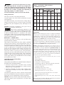
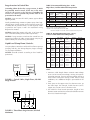
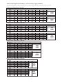
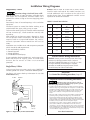
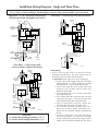
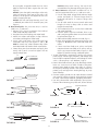
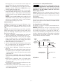
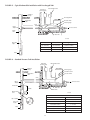
OWNERS MANUAL
INSTALLATION AND OPERATING INSTRUCTIONS
REPAIR PARTS LIST
40 and 70 GPM Models
4" SUBMERSIBLE PUMPS
1-1/2 through 7-1/2 H.P.
NOTICE: Mount model and serial nameplate labels at
well head or on control box. Provide complete nameplate
information with any service or part inquiries. Record the following
nameplate information here for future reference:
Pump Model No.
Pump Serial No.
Motor Model No.
Motor Serial No.
H.P.
Volts/Hz/Ph
Rated Amp Draw
Printed in U.S.A. © 1995, Foreign Sales Corporation
U49 (Rev. 2/20/95)
TABLE OF CONTENTS
Carefully read and follow all safety instructions in this
manual or on pump.
Safety Instructions..............................................................2
Pre-Installation...................................................................2
Electrical:
Wiring/Grounding .......................................................2-3
Surge Arresters/Fusing Data ............................................4
Cable Data ..................................................................5-6
Wiring Diagrams .......................................................7-10
Cable Splicing .........................................................10-12
Initial Startup ...................................................................12
Connecting to Tank/Water System..............................12-13
Troubleshooting Guide...............................................14-15
Warranty .........................................................................16
This is the safety-alert. When you see this
symbol on your pump or in this manual, look for
one of the following signal words and be alert to
the potential for personal injury:
warns about hazards that will cause serious
personal injury, death or major property damage if ignored.
warns about hazards that can cause serious
personal injury, death or major property damage if ignored.
warns about hazards that will or can cause
minor personal injury or property damage if ignored.
PRE-INSTALLATION
The word NOTICE indicates special instructions which are
important but not related to hazards.
Inspect pump and motor for delivery damage. Report any
damage immediately to the shipping carrier or to your
dealer.
To avoid serious or fatal personal injury and possible
property damage, carefully read and follow the safety
instructions.
1.
The well driller should thoroughly develop the well (that is,
pump out all fine sand and foreign matter) before pump is
installed.
Under certain conditions, submersible
pumps can develop extremely high
pressure. Install a pressure relief valve
capable of passing entire pump flow at 75 PSI (517 kPa).
Pump performance is based on pumping clear, cold, solid
water.
Warranty is void in the following conditions:
• If pump has pumped excessive sand – excessive sand
can cause premature wear to pump.
• If water is corrosive.
• If entrained gas or air are present in the water being
pumped – these can reduce flow and cause cavitation
which can damage pump.
• If pump has been operated with discharge valve closed –
severe internal damage will result.
Install pump at least 15 to 20' (4.5 to 6 M) below the lowest
water level reached with pump running (lowest draw-down
water level), and at least 5' (1.5M) above the bottom of the
well.
Do not allow pump, pressure tank, piping, or any
other system component containing water to
freeze. Freezing may damage system, leading to injury
or flooding. Allowing pump or system components to
freeze will void warranty.
2.
Hazardous
voltage
Can shock, burn or cause death. To avoid
dangerous or fatal electric shock hazard,
use pump only in a water well.
Install, ground and wire pump according to local
code requirements.
Disconnect electrical power supply before installing or servicing pump.
Wiring/Grounding:
Make sure line voltage and frequency of power
supply match motor nameplate voltage and
frequency.
Hazardous
voltage
3. Install pump according to all plumbing, pump and well
code requirements.
Can shock, burn, or cause death. Permanently ground pump, motor and control box
before connecting power supply to motor.
Ground pump and motor in accordance with all codes and
ordinances that apply. Use a copper ground wire at least as
large as wires carrying current to motor.
4. Test well water for purity before using well. Call your
local health department for testing procedure.
Motor is supplied with a copper ground wire. Splice this
ground wire to a copper conductor that matches motor
wire size specified in Table IV, Page 5. See Pages 10 to 12
for cable splicing instructions.
5. During installation, keep well covered as much as
possible to prevent leaves and foreign matter from falling
into well. Foreign objects in well can contaminate the
water and cause serious mechanical damage to the
pump.
Permanently ground pump, motor and control box before
connecting power cable to power supply. Connect ground
wire to approved ground first and then connect to
equipment being installed.
Do not ground to a gas supply line.
2
Fire and electrical shock hazard. If using a
drop cable larger than No. 10 (5mm2) (for example, No. 8
(7mm2) wire) between pump and control box, run cable to
a separate junction box. Connect junction box to control
box with a No. 10 (5mm2) or smaller wire (depending on
amp rating of pump – see Table II and III).
TABLE I – Overloads for 3 Phase 60 Hertz
4” Franklin Electric Motors
Heaters for
Overload Relays
Furnas
Allen
GE
(Note 1)
Bradley
(Note 2)
Adjustable
Relays
(Note 3)
Set Max.
HP
Volts
NEMA
Starter
Size
1.5
230
460
575
00
00
00
K41
K29
K27
J22
J15
J13
L750A
L380A
L310A
5.89
2.94
2.39
6.4
3.2
2.6
All wiring must meet local code requirements.
2
Use only copper wire when making connections to pump
and control box.
230
460
575
0
00
00
K43
K33
K29
J25
J18
J15
L910A
L463A
L380A
7.36
3.68
2.94
8.0
4.0
3.2
For more information, contact your local code officials.
Wiring Connections:
3
To avoid over-heating wire and excessive voltage drop at
motor, be sure that wire size is at least as large as size listed
in Table IV for your horsepower pump and length of wire
run.
230
460
575
0
0
0
K52
K37
K33
J28
J20
J18
L122B
L618A
L463A
9.75
4.88
3.86
10.6
5.3
4.2
5
230
460
575
1
0
0
K61
K49
K42
J32
J25
J23
L199B
L100B
L825A
16.0
8.0
6.44
17.4
8.7
7.0
NOTICE: See Pages 8 through 10 for typical wiring
hookups and control box identification.
7.5
230
460
575
1
1
1
K67
K55
K52
J36
J29
J27
L293B
L147B
L122B
23.5
11.8
9.38
25.5
12.8
10.2
When built-in overheating protection is not
provided, use with an approved overload equipped motor
control that matches motor input in full load amps. Select
or adjust overload element(s) in accordance with control
instructions. When built-in overheating protection is
provided, use with an approved motor control that matches
input in full load amperes.
FOOTNOTES:
NOTE 1: Heaters listed apply to Innova 45 designs and Definite
Purpose Class 16 starters through their available range, and to
standard starters in larger sizes. Set overload relay adjustments no
higher than 100%, unless necessary to stop nuisance tripping with
measured amps in all lines below nameplate maximum.
ROTATION – (3 PHASE ONLY)
To make sure motor is running in the right direction,
proceed carefully as follows:
NOTE 2: General Electric heaters are type CR123 usable only on
type CR124 overload relays. Adjustment should be set no higher
than 100%, unless necessary to stop nuisance tripping with
measured amps in all lines below nameplate maximum.
After electrical connections have been made as outlined,
and with pump hanging in well supported from clamp on
the discharge pipe, momentarily close the switch connecting the motor to the power supply line. Note direction
of jerk as motor starts. If connections are properly made,
pump will jerk clockwise when looking into the pump
discharge when started. If jerk is counter-clockwise, this
means the motor is running in the wrong direction.
Interchange any two cable leads where they connect to the
“lead” terminals in the magnetic starter. With connections
properly made, and pump lowered into water, throw the
switch again and the pump should deliver water according
to the performance charts.
NOTE 3: Adjustable overload relay amp settings apply to
approved types listed below. Request approval of other types from
Franklin Electric. Set relay adjustment at specified SET amps; do
not increase setting unless motor trips with measured amps in all
lines within nameplate maximum amps. Do not increase setting
past MAX value shown. Some approved types may not be
available for all listed motor ratings. When using relays with
current transformers, set relay to specified amps divided by
transformer ratio. Approved relays include:
AEG series b175, b27S 11-17A and 15-23A, b27-2 11-17A
and 15-23A.
ASEA type RVH40.
Overload Protection of Three Phase
Submersible Motors
Allen Bradley bulletin 193.
Submersible motors differ from standard motors and require
the following for overload protection:
Fanal types K7 or K7D through K400.
1. Ambient compensation: provides motor winding
protection in low air temperatures, avoids nuisance
tripping in high air temperatures.
Klockner-Moeller types Z00, Z1, Z4, PKZM3.
General Electric CR4G1T-, CR4G1W-, CR4G2W-, CR4G3W-.
Lovato RC-22 to RC-80.
RTE Delta types DQ, LR1-D, LR1-F.
2. Quick-trip overloads: To protect motor windings when
motor stalls, overloads must trip within approximately
10 seconds.
Sprecher and Schuh types CT, CT1, CTA1.
Siemens types 3UA50, -52, -54, -58, -59, -62.
Square D Class 9065 types TUP, MR, TD, TE, TF, TR, TJE.
The following table lists correct ambient-compensated
quick-trip overloads for several manufacturers. Approval of
other types may be requested from motor manufacturer.
Telemecanique type LR1-D, LR1-F.
Westinghouse types FT13, FT23, FT33, FT43, K7D, K27D,
K67D
NOTICE: Warranty on three phase submersible motors is
void unless proper quick trip protection in all three motor
lines is used.
Other relay types from these and other manufacturers should not
be used without approval of Franklin Electric.
3
TABLE II: Recommended Fusing Data - 60 Hz,
Single Phase, Franklin Submersible Pump Motors
Surge Arresters in Control Box
Grounding: When the box has a surge arrester, it MUST
be grounded, metal to metal, all the way to the water
strata for the arrester to be effective. Grounding the
arrester to a driven ground rod provides little or no
protection for the motor.
3-Wire Application - Capacitor Run
Volts/Hz/
HP
Phase
1-1/2 230/60/1
2
230/60/1
3
230/60/1
5
230/60/1
NOTICE: Surge arresters DO NOT protect against direct
lightning strikes.
Install grounded surge arresters to protect pump from highvoltage surges. Install arrester on the incoming power line
to control box or pressure switch, as close to pump motor
as possible. See Figures 1 and 2 for installation wiring
diagrams for arresters.
Winding
Resistance*
R to Y
B to Y
6.2-12.0
1.5-2 3
5.2-7.1
1.6-2 3
3.0-4.9
0.9-1.5
2.1-2.8
0.68-1.0
Max
Load
Amps
11.5
13.2
17.0
27.5
Locked
Rotor
Amps
52.8
51.0
71.0
118.0
Fuze Size
Standard/
Dual Element
30/15
30/15
45/20
70/30
2-Wire Application - Induction Run**
1-1/2
230/60/1
1.5-1.9
13.1
56.8
35/15
*Red to Yellow = start winding resistance;
Black to Yellow = main winding resistance.
**NOTE: 2-Wire motor leads are not color coded.
Overload is located in motor and cannot be tested from above ground.
NOTICE: Ground the arrester with a No. 10 or larger bare
wire. Ground according to local code requirements.
TABLE III: Recommended Fusing Data - 60 Hz.,
3 Phase Franklin Submersible Pump Motors
NOTICE: If surge arresters wired into the control box are
against local electrical code, contact power company or
hydro authority for correct wiring information.
Max. Output
Volts/
(S.F. Load)
Line to
Locked
Line
Rotor
Fuse Size
Dual
HP
Hz./Ph.
Amps
Watts
Resistance
Amps
Stand.
Elem.
1.5
Use pump down controls on wells with low flow to prevent
pumping well dry. See Wiring diagrams, Pages 8 through
10, for proper installation.
230/60/3
460/60/3
575/60/3
6.3
3.1
2.5
2000
2000
2000
3.2-4.1
11.3-15.0
17.6-23.4
34
17
14
20
15
15
8
4
3
2
230/60/3
460/60/3
575/60/3
8.1
4.1
3.2
2580
2580
2690
2.4-3.0
9.7-12.0
15.1-18.7
46
23
18
20
15
15
10
5
4
NOTICE: Ground controls according to local code requirements.
3
230/60/3
460/60/3
575/60/3
10.9
5.5
4.4
3420
3420
3420
1.8-2.2
7.0-8.7
10.9-13.6
61
31
24
30
15
15
15
7
6
5
230/60/3
460/60/3
575/60/3
17 8
8.9
7.1
5810
5810
5810
0.93-1.2
3.6-4.4
5.6-6.9
104
52
42
45
25
20
20
10
8
7.5
230/60/3
460/60/3
575/60/3
26.4
13 2
10 6
8450
8450
8450
.61-.75
2.4-3.4
3.5-5.1
164
82
65
70
35
30
30
15
12
Liquid Level (Pump Down) Controls:
Surge
Arrester
Control
Box
NOTE:
L1 L2 R Y B
1. Maximum cable lengths shown maintain motor voltage
at 95% of service entrance voltage, running at maximum
nameplate amperes. If service entrance voltage will be at
least motor nameplate voltage under normal load
conditions, 50% additional length is permissible for all
sizes.
FIGURE 1 – Typical 3 Wire, Single Phase, 230 Volt
Surge Arrester
2. Sizes given are for copper wire. For aluminum wire, go
two sizes larger. For example, if table lists #12 (3mm2)
copper wire, use #10 (5mm2) aluminum wire.
3. For reliable 3 Phase starter operation, length of wire
between starter and service entrance should be not more
than 25% of total wire length.
Line
Surge
Arrester
L1
T1
L2
L3
T2
T3
FIGURE 2 - Three Phase Surge Arrester (650 Volt
Maximum)
4
Table IV Cable Length in Feet and Meters – Service to Motor, Copper Conductors
Meets NEC for jacketed 75°C cable (except lengths marked *. Lengths marked * meet NEC for individual conductor 75°C cable).
1 Phase, 2 or 3 Wire, 60 Hz., 230 Volts
Wire Size – AWG
H.P.
1.5
2
3
5
14
190
150
120*
0
12
310
250
190
0
10
480
390
300
180
8
770
620
470
280
H.P.
1.5
2
3
5
1.5
57
45
36
0
2.5
93
75
57
0
4
144
117
90
54
6
231
186
141
84
6
1200
970
750
450
4
1870
1530
1190
710
3
2320
1910
1490
890
2
2850
2360
1850
1110
1
3500
2930
2320
1390
0
4280
3620
2890
1740
}
Cable
Length
in Feet
35
855
708
555
333
50
1050
879
696
417
70
1284
1086
867
522
}
Cable
Length
in Meters
2
6160
4770
3660
2190
1560
1
7530
5860
4480
2690
1920
0
9170
7170
5470
3290
2340
}
Cable
Length
in Feet
35
1848
1431
1098
657
468
50
2259
1758
1344
807
576
70
2751
2151
1641
987
702
}
Cable
Length
in Meters
Wire Size - Millimeters Squared
10
360
291
225
135
16
561
459
357
213
25
696
573
447
267
3 Phase, 3 Wire Cable, 60 Hz., 230 Volts
Wire Size – AWG
H.P.
1.5
2
3
5
7.5
14
420
320
240
140*
0
12
670
510
390
230
160*
10
1060
810
620
370
260
8
1670
1280
990
590
420
H.P.
1.5
2
3
5
7.5
1.5
126
96
72
42
0
2.5
201
153
117
69
48
4
318
243
186
111
78
6
501
384
297
177
126
6
2610
2010
1540
920
650
4
4050
3130
2400
1430
1020
3
5030
3890
2980
1790
1270
Wire Size - Millimeters Square
10
783
603
462
276
195
16
1215
939
720
429
306
6
4
25
1509
1167
894
537
381
3 Phase, 3 Wire Cable, 60 Hz., 460 Volt
Wire Size – AWG
H.P.
1.5
2
3
5
7.5
14
1700
1300
1000
590
420
H.P.
1.5
2
3
5
7.5
.5
510
390
300
177
126
12
2710
2070
1600
950
650
10
4270
3270
2520
1500
1070
8
6580
5150
3970
2360
1690
8050
6200
3700
2640
5750
4100
10
16
}
Cable
Length
in Feet
}
Cable
Length
in Meters
Wire Size - Millimeters Squared
2.5
813
621
480
285
195
4
1281
981
756
450
321
6
1974
1545
1191
708
507
2415
1860
1110
792
1725
1230
3 Phase, 3 Wire Cable, 60 Hz., 575 Volt
Wire Size – AWG
H.P.
1.5
2
3
5
7.5
14
2620
2030
1580
920
660
H.P.
1.5
2
3
5
7.5
1.5
786
609
474
276
198
12
4180
3250
2530
1480
1060
10
6730
5110
3980
2330
1680
8
8060
6270
3680
2650
6
5750
4150
}
Cable
Length
in Feet
}
Cable
Length
in Meters
Wire Size - Millimeters Squared
2.5
1254
975
759
444
318
4
2019
1533
1194
699
504
6
2418
1881
1104
795
10
1725
1245
5
How to size Wire Cable correctly when using more than one gauge of wire
160 Ft. AWG 10
(53.3% of Allowable Cable)
48.8m 4mm2
(53.3% of Allowable Cable)
310 Ft. AWG 6
Cable
Service Entrance
(Main Fuse Box
From Meter)
Pump
Controls
3 HP (2.2 kw)
230V 1Ph Motor
94.5m 10mm2
(41.3% of
Allowable
Cable)
Cable
Service Entrance
(Main Fuse Box
From Meter)
218 0993
Pump
Controls
3 HP (2.2 kw)
230V 1Ph Motor
(41.3% of
Allowable
Cable)
700 0294
FIGURE 3
English Measurement
Metric Measurement
Calculating cable size when two different sizes can be
used.
Sometimes conditions make it desirable to use more than
one cable size in an installation.
For example: Replace a pump with a 3 HP, 230 volt, single
phase motor, with the motor setting at 310' down the well
and with 160' of #10 cable buried between the service
entrance and the well head. In order to avoid replacing the
buried cable, the question is: What size cable is required
in the well? Calculate as follows:
1. According to Table IV, a total of 300' of #10 cable is
allowed to power the 3 HP motor. The per cent of this
total that has been used by the 160' of cable in the
buried run is: 160'/300' = .533 = 53.3%.
2. With 53.3% of the allowable cable already used, 46.7%
of the total length is left for use in the well. To avoid
running a cable that is too long and lowering the voltage
to the motor, we have to find a cable size large enough
so that 310' is less than 46.7% of the total length
allowed for that size.
3. Trying #8 cable, Table IV shows that the total allowable
length for a 3 HP motor is 470'.
470' x 46.7% = 470' x .467 = 219.5'.
This is not long enough.
4. Trying #6 cable, Table IV shows that the total allowable
length is 750'.
750' x 46.7% = 750' x .467 = 350.25'.
This is longer than needed. Therefore, #6 cable can be
used for the 310' of cable in the well.
Any combination of sizes can be used, provided that the
total percentage of the length of the two sizes of cable
does not exceed 100% of the total allowed lengths.
Calculating cable size when two different sizes can be
used.
Sometimes conditions make it desirable to use more than
one cable size in an installation.
For example: Replace a pump with a 3 HP, 230 volt, single
phase motor, with the motor setting at 94.5M down the
well and with 48.8M of 4mm2 cable buried between the
service entrance and the well head. In order to avoid
replacing the buried cable, the question is: What size cable
is required in the well? Calculate as follows:
1. According to Table IV, a total of 91.4M of 4mm2 cable is
allowed to power the 3 HP motor. The per cent of this
total that has been used by the 48.8M of cable in the
buried run is: 48.8M/91.4M = .534 = 53.4%.
2. With 53.4% of the allowable cable already used, 46.6%
of the total length is left for use in the well. To avoid
running a cable that is too long and lowering the voltage
to the motor, we have to find a cable size large enough
so that 94.5M is less than 46.6% of the total length
allowed for that size.
3. Trying 6mm 2 cable, Table IV shows that the total
allowable length for a 3 HP motor is 143M.
143M x 46.6% = 143M x .466 = 66.6M.
This is not long enough.
4. Trying 10mm2 cable, Table IV shows that the total
allowable length is 225M.
225M x 46.6% = 225M x .466 = 105M.
This is longer than needed. Therefore, 10mm2 cable can
be used for the 94.5M of cable in the well.
Any combination of sizes can be used, provided that the
total percentage of the length of the two sizes of cable
does not exceed 100% of the total allowed lengths.
6
Installation Wiring Diagrams
NOTICE: Match motor to control box as shown below.
Franklin motor and control box model numbers may
include additional suffix numbers to the right of the
numbers shown here. These additional numbers are not
important for control box selection.
Single Phase, 3 Wire
Hazardous voltage. Can shock, burn, or kill.
Ground control box, all metal plumbing, and motor frame
with copper wire in compliance with local codes. Use a
ground wire at least as large as the wires supplying power
to motor.
Permanently close all unused openings in this and other
equipment.
Disconnect power to control box before working on or
around control box, pipes, cable, pump, or motor.
To be sure that starting relay will function and that overload
will not “nuisance trip”, install control box vertically with
top side up.
Wire control box as shown on pages 8 through 10. Pump
will not operate without control box, and deluxe boxes
require a switch or a jumper lead between ‘SW’ and ‘L2’
terminals. Operation without control box will burn out
motor.
Installation must include circuit and component protection
which meet local code requirements.
If main overload trips, look for:
1. Shorted Capacitor
2. Voltage Problems
3. Overloaded or locked pump.
If start overload or both overloads trip(s), replace start relay.
Reset and analyze for tripping cause. To avoid motor
burnout, do not remove or short circuit overload
protection.
TABLE V: Control Box Selection
Voltage
1/2
115
1/2
230
3/4
230
1
230
1-1/2
230
Motor
No.
214304
214504
214305
214505
214307
214507
214308
214508
224300
2
230
224301
3
230
224302
5
230
224303
Control Box
No.
28010449
28010549
28010749
28010849
28230081
28230181
28230183
28230281
28230283
28211381
28211383
Pressure Switch Wiring Information
NOTICE: Starting current (inrush current) from large
motors may damage pressure switch. Pressure
switches installed with motors of 1-1/2 HP (1.1 KW)
or larger should be wired through a magnetic
contactor to avoid burning out pressure switch.
Consult factory for further information.
Single Phase, 2 Wire
2-Wire pumps have two power supply wires (Red/Black)
and one ground wire (Green). Control box is not required.
See Figure 4 for correct hook-up information for 230 Volt
2-Wire motors only.
To Line
HP
NOTICE:
See Control box checking procedures, Page 15.
Ground
Important Electrical Grounding Information
L1
M1
L2
M2
Fused
Disconnect
Switch
Hazardous voltage. Can shock, burn, or kill. To
reduced the risk of electrical shock during pump operation, ground
and bond the pump and motor as follows:
A. To reduce risk of electrical shock from metal parts of the assembly
other than the pump, bond together all metal parts accessible at the
well head (including metal discharge pipe, metal well casing, and
the like). Use a metal bonding conductor at least as large as the
power cable conductors running down the well to the pump’s
motor.
B. Clamp or weld (or both if necessary) this bonding conductor to the
grounding means provided with the pump, which will be the
equipment-grounding terminal, the grounding conductor on the
pump housing, or an equipment-grounding lead. The equipmentgrounding lead, when provided, will be the conductor having green
insulation; it may also have one or more yellow stripes.
C. Ground the pump, motor, and any metallic conduit that carries
power cable conductors. Ground these back to the service by
connecting a copper conductor from the pump, motor, and conduit
to the grounding screw provided within the supply-connection box
wiring compartment. This conductor must be at least as large as the
circuit conductors supplying the pump.
Pressure
Switch
Red
Black
Well
Casing
Ground
(Green)
336 1093
Save these instructions.
Figure 4 - Single Phase, 2 Wire Connections
7
Installation Wiring Diagrams - Single Phase
Follow color coding when connecting control box (Yellow to Y, Red to R, Black to B).
For 1-1/2 HP (1.1 KW) and larger, install magnetic contactor when system includes a pressure switch.
Open System - Single Phase - 1/2 HP thru 5 HP
Standard Control Box
Single Phase - 1/2 HP thru 5 HP Standard Control
Box with Pressure Switch
(One Pump for Two Houses) with Adequate Rated
Pressure Switch
Ground
To Line
To Line
Ground
To Line
Control
Box
Fused
Disconnect
Switch
L1 L2 R Y B
Fused
Disconnect
Switch
Red
Yellow
Black
L1
M1
L2
M2
Pressure
Switch
L1
M1
L2
M2
Pressure
Switch
CONTROL
BOX
Aux. Relay
or Equivalent
Well
Casing
L1 L2 R Y B
Red
Yellow
Black
Ground
357 0893
Ground
Well
Casing
Single Phase - 1/2 thru 5 HP Standard Control Box
with Adequate Rated Pressure Switch
To Line
359 0893
Ground
Single Phase - 1/2 thru 5 HP Standard Control Box
with Liquid Level Control
CONTROL
BOX
To Line
Ground
L1 L2 R Y B
L1
M1
L2
M2
Fused
Disconnect
Switch
Fused
Disconnect
Switch
Control
Box
Pressure
Switch
L1 L2 R Y B
Red
Yellow
Black
Liquid
Level
Control
Ground
1
8
2
9
5
6
7
Well
Casing
355 0893
High
Electrode
NOTICE:
See Control box checking procedures, Page 15.
See Pressure Switch Wiring Information, Page 7.
Low
Electrode
8
Red
Yellow
Black
Well
Casing
Ground
353 0893
Installation Wiring Diagrams - Single Phase
Follow color coding when connecting control box (Yellow to Y, Red to R, Black to B).
For 1-1/2 HP (1.1 KW) and larger, install magnetic contactor when system includes a pressure switch.
Single Phase - 1/2 thru 5 HP Standard Control Box
with Pressure Switch & Liquid Level Control
220V Line
Single Phase - 2, 3 & 5 HP Deluxe Control Boxes
with Pressure Switch
Ground
To Line
Ground
Pressure
Switch
Fused
Disconnect
Switch
L1
M1
Control
Box
L2
M2
L1 L2 R Y B
Control
Box
SW L1 L2 Y B R
BW Liquid
Level Control
1
8
2
9
5
L2
6
M2
Pump
Well
Casing
Low
Electrode
Ground
356 0893
Ground
Well
Casing
472 0893
Single Phase - 2, 3 & 5 HP Deluxe Control Boxes
with Liquid Level Control
Single Phase - 2, 3 & 5 HP Deluxe Control Boxes
Open System
220V Line
Pressure
Switch
Yellow
Black
Red
7
Red
Yellow
Black
High
Electrode
M1
L1
Fused
Disconnect
Switch
Ground
Control
Box
BW Liquid
Level Control
SW L1 L2 Y B R
Control
Box
SW L1 L2 Y B R
1
8
6
2
9
7
5
Fused
Disconnect
Switch
High
Electrode
Yellow
Black
Red
Low
Electrode
Pump
Yellow
Black
Red
Well
Casing
Ground
354 0893
Well
Casing
Ground
473 0893
NOTICE:
See Control box checking procedures, Page 15.
See Pressure Switch Wiring Information, Page 7.
9
Installation Wiring Diagrams - Single and Three Phase
Follow color coding when connecting control box (Yellow to Y, Red to R, Black to B).
For 1-1/2 HP (1.1 KW) and larger, install magnetic contactor when system includes a pressure switch.
Single Phase - 2, 3 & 5 HP Deluxe Control Boxes
with Pressure Switch and Liquid Level Control
Three Phase - 11⁄2 HP & Larger with Pressure Switch
Pressure
Switch
Ground
To Line
Pressure
Switch
Fused
Disconnect
Switch
L1
M
L
M
L
Control
Box
M1
SW L1 L2 Y B R
L2 M2
Fused
Disconnect
Switch
BW Liquid
Level Control
1
8
2
9
5
7
Yellow
Black
Red
High
Electrode
Low
Electrode
L1
L2
L3
T1
T2
T3
Magnetic
Starter
6
Ground
Well
Casing
358 0893
Well
Casing
Three Phase - 11⁄2 HP & Larger with
Pressure Switch & Liquid Level Control
362 0893
Pressure
Switch
M
L
M
L
Cable Splicing:
1. Splice cable to motor leads. Use one of the three
methods outlined below. Use only copper wire for
connections to pump motor and control box.
A. Taped splice (Wire sizes No. 8 (7mm2) and larger):
1. Cut off motor leads. Stagger lead and wire length
so that 2nd lead is 2" (50mm) longer than 1st lead
and 3rd lead is 2" (50mm) longer than second.
2. Cut off cable ends. Be sure to match colors and
lengths of wires in drop cable to colors and
lengths of motor leads.
3. Trim insulation back 1/2" (13mm) from cable ends
and motor lead ends.
4. Insert motor lead ends and cable ends into butt
connectors (see Figure 5). Be sure to match wire
colors between drop cable and motor leads.
5. Using crimping pliers (Figure 8), indent butt
connector lugs (see Figure 6) to attach wires.
6. Cut “Scotchfil” electrical insulation putty into 3
equal parts and form tightly around butt connectors. Be sure scotchfil overlaps insulated part
of wire.
7. Using #33 Scotch tape, wrap each joint tightly;
cover wire for about 1-1/2" (38mm) on each side
of joint. Make four passes with the tape. In other
words, when finished you should have four layers
Fused
Disconnect
Switch
Magnetic
Starter
1
8
2
9
5
L1
L2
L3
T1
T2
T3
6
7
Liquid
Level
Control
High
Electrode
Low
Electrode
Well
Casing
361 0893
NOTICE:
See Control box checking procedures, Page 15.
See Pressure Switch Wiring Information, Page 7.
10
of tape tightly wrapped around the wire. Press
edges of tape firmly down against the wire (see
Figure 9).
NOTICE: Since the tightly wound tape is the only
means of keeping water out of the splice, the
efficiency of the splice will depend on the care
used in wrapping the tape.
NOTICE: For wire sizes larger than #8, (7mm2) use
a soldered joint rather than Scotchfil putty (see
Figure 7).
B. Heat-shrink splice (For wire sizes #14, 12 and 10
AWG, or 2, 3, and 5mm2):
1. Remove 3/8" (10mm) insulation from ends of
motor leads and drop cable wires.
2. Put plastic heat shrink tubing over motor leads.
3. Match wire colors and lengths in drop cable to
wire colors and lengths of motor leads.
4. Insert cable and motor wire ends into butt
connectors and crimp (See Figures 5 and 6). BE
SURE to match wire colors between drop cable
and motor leads. Pull leads to check connections.
5. Center tubing over butt connector and apply heat
evenly with a torch (a match or lighter will not
supply enough heat).
2.
1/2"
(12.7mm)
BUTT CONNECTOR
FIGURE 5
3.
INDENT HERE
FIGURE 6
4.
ALTERNATE METHOD
TWIST AND SOLDER
FIGURE 7
5.
NOTICE: Keep torch moving. Too much concentrated heat may damage tubing (see Figure 10).
C. Butt Connectors with plastic insulators (for 14, 12
and 10 Gauge AWG Wire, or 2, 3 and 5mm2 wire):
1. Cut off motor leads. Stagger lead and wire length
so that 2nd lead is 4" (100mm) longer than 1st
lead and 3rd lead is 4" (100mm) longer than
second.
2. Cut off cable ends. Be sure to match colors and
lengths of wires in drop cable to colors and
lengths of motor leads.
3. Trim insulation back 1/2" (13mm) from cable ends
and motor lead ends.
4. Unscrew plastic caps from insulators. Place a cap
and a neoprene gasket sleeve on each wire end to
be spliced (see Figure 11).
5. Slide insulator body onto one wire end (Fig. 11).
6. Insert wire end into butt connector and crimp (see
Figure 12). Be sure to match cable and motor wire
colors
7. Center insulator body over splice and slide
neoprene sleeves into body as far as they will go.
Screw caps onto insulator body (Figure 13) and
tighten by hand for a strong, waterproof splice.
To test submersible, momentarily connect it to proper
power supply. Power supply frequency and voltage must
match motor nameplate frequency and voltage to within
±10%. (3 Phase pumps – see “Rotation,” Page 3).
Fasten cable leads securely to pump discharge section;
leave 4-5" (100-127mm) of slack in leads at this point.
Securely fasten leads to plastic pipe within 6" (150mm)
of the pump discharge section. Use torque arresters to
protect pump and pipe from twisting damage as pump
starts and stops.
Connect copper ground wire to motor bracket. Ground
wire must be at least as large as wires supplying current
to motor. Consult local codes for grounding information.
Use only submersible cable supplied by pump manufacturer. When lowering pump into well, secure cable to
NOTCH
END CAP
1"
2
INSULATOR BODY
1"
2
12.7mm 12.7mm
FIGURE 8
FIGURE 9
FIGURE 11
COMPLETED SPLICE
FIGURE 12
GASKET
BUTT CONNECTOR OR
CRIMP OR SOLDER
CONNECTOR
CAP SCREWED ON
HEAT SHRINK TUBING
GASKET SLEEVE IN PLACE
476 0893
FIGURE 13
FIGURE 10
11
INSULATOR BODY
CENTERED OVER SPLICE
discharge pipe at 10' (30.5M) intervals with Scotch #33
electrical tape. Take care not to damage pump cable.
NOTICE: To avoid dropping the pump down the well or
damaging cable or cable splices, NEVER allow pump
cable to support weight of pump.
6. If a standard galvanized pressure tank is being used,
install two bleeder orifices about 2' (.6M) apart as shown
in Figure 16, Page 13. These orifices will automatically
charge tank with air. See Table III to determine orifice
location.
NOTICE: If Pre-charged (bladder) tank is used, DO NOT
install bleeder orifices. If pump and pre-charged tank are
replacing a standard tank system, remove bleeder
orifices before installing pump in well.
CONNECTING TO TANK/WATER SYSTEM
Hazardous pressure. Submersible pumps can
develop very high pressure in some situations. To prevent
tank blowup, install a pressure relief valve able to pass full
pump flow at 100 PSI (690kPa). Install this relief valve
between pump and tank.
NOTICE: Allowing pump or piping system to freeze may
severely damage pump and will void warranty. Protect
pump and entire piping system (including pressure tank)
from freezing.
Standard Tank Hookup:
See Figure 16, Page 13 for piping connections to standard
pressure tank and for correct distance of bleeder orifices
from pressure tank.
INITIAL START-UP
NOTICE: NEVER operate pump with discharge valve
completely closed. Pump can destroy itself if run with
discharge shut off (“deadheaded”) and warranty will be
void.
NOTICE: To avoid sand-locking pump, follow procedure
below when starting pump for the first time. NEVER start a
pump with discharge completely open unless you have
done this procedure first.
1. Connect a pipe elbow, a short length of pipe and a gate
valve to pump discharge at well head (see Figure 14).
2. Mount motor control box (3-wire pump), or magnetic
starter (3-phase pump) in a permanently weather
proofed place. Make sure that controls will not be
subjected to extreme heat or excess moisture.
3. Make sure controls are in OFF position.
4. Connect motor leads and power supply to motor control
box or magnetic starter (see Wiring Diagrams, Pages 8
through 10). DO NOT START PUMP YET.
5. Set gate valve on discharge 1/3 open; start pump (see
Figure 14).
6. Keep gate valve at this setting while water pumps out
on ground. Let it run until water is clear of sand or silt.
(To check solids in water, fill a glass from pump and let
solids settle out).
7. When water is completely clear at 1/3 setting, open
gate valve to approximately two-thirds open and repeat
process.
8. When water is completely clear at 2/3 setting, open
gate valve completely and run pump until water is
completely clear.
9. Remove gate valve for permanent installation near tank
(see Figures 15 and 16, Page 13).
10. Install sanitary well seal or pitless adapter unit, well
unit, electrical conduit and surface piping according to
local code requirements.
Pre-charged Pressure Tank Hookup:
See Figure 15, Page 13 for piping connections to precharged pressure tank.
NOTICE: Check air pre-charge in tank before starting
pump. Adjust pre-charge to 2 PSI (13.8kPa) below pump
cut-in setting. (For example, a pre-charge tank used with a
30-50 switch should be pre-charged with air to 28 PSI
(193kPa). Adjust pre-charge by either adding or bleeding
air through tire valve located on top of tank. Check precharge annually and adjust as needed.
Control
center
or
electrical
disconnect
box
Temporary wiring
to control center or
electrical disconnect box
Temporary piping
Gate valve
Pump installation
for developing a well
FIGURE 14
12
Pump in well
689 0993
FIGURE 15 – Typical Submersible Installation with Pre-charged Tank
Electrical disconnect
Control box
(3 wire models)
Ventilated
well cap
Pre-charged tank
Submersible
cable
Pressure switch
Pressure gauge
Union
Relief valve
Pitless
adaptor
To house service
Check
valve
Gate valve
690 0993
Tape cable
to pipe
Cut-In PSI
Cut-Off PSI
Pre-charge Pressure
20 (138 kPa)
40 (276 kPa)
18 PSI (124 kPa)
30 (207 kPa)
50 (345 kPa)
28 PSI (193 kPa)
40 (276 kPa)
60 (414 kPa)
38 PSI (262 kPa)
Pump
FIGURE 16 – Standard Pressure Tank Installation
Control box
(3 wire models)
Electrical disconnect
Ventilated
well cap
Pressure gauge
Air volume control
Pressure switch
Submersible
cable
Union
Pitless
adaptor
To house service
Check valve
Gate valve
See table
Bleeder orifice
& tee
Relief valve
2 ft.
(.6m)
691 0993
CHECK VALVE DISTANCE TO TOP BLEEDER ORIFICE
TANK SIZE
DISTANCE
Pipe coupling
Tape cable
to pipe
Pump
13
42 Gallon (159L)
2' (.6M)
82 Gallon (310L)
3' (.9M)
120 Gallon (454L)
5' (1.4M)
220 Gallon (833L)
5' (1.4M)
315 Gallon (1192L)
10' (3.0M)
525 Gallon (1987L)
15' (4.6M)
TROUBLESHOOTING GUIDE
PROBLEM
Motor will not start but
fuses do not blow
No voltage
Fuses blow or overload
protector trips when
motor starts
Wrong size fuse or wrong
size time delay fuse.
Wire size too small.
Starting capacitor
defective or blown.
Low or high voltage.
Cable leads not correctly
connected to control box.
Broken wire in control
box.
Pump or motor stuck or
binding.
Fuses blow or overload
protector trips when
motor is running
Low or high voltage.
High ambient
(atmospheric) temperature.
Control box with wrong
voltage or horsepower
rating.
Wire size too small.
Cable splices or motor
leads grounded, shorted,
or open.
Pump starts too
frequently
Leaks in system.
Pressure switch.
Tank waterlogged.
Leak in drop pipe.
Pressure switch too far
from tank.
CHECK
CORRECTIVE ACTION
No voltage at fuse box.
No voltage at pressure switch
No voltage at control box.
Cable or splices bad.
Control box incorrectly wired.
Replace blown fuses.
Replace faulty pressure switch.
Rewire supply to control box.
Consult licensed electrician or serviceman.
Reconnect control box correctly (see wiring
diagrams, Pages 7 through 9).
Check fuse size against chart, Page 4.
Install correct fuse or time delay fuse.
Check wire size against chart, Page 5.
Check control box to see if starting
capacitor has blown out.
Check that line voltage is within ±10% of
nameplate rated voltage while motor is
running.
Check control box wiring diagram
against incoming power hookup.
Check drop cable color coding.
Install correct size wire.
Replace starting capacitor.
Examine all connections and wiring in
control box.
Check for locked rotor in pump.
If voltage variation is greater than ±10%, call
power company to adjust voltage.
Reconnect leads to match wiring diagram in
control box cover.
Reconnect drop cable so cable color code
matches motor lead color code.
Disconnect power and repair or replace faulty
wire.
If necessary, pull pump (make all possible
above ground checks first). If pump is locked,
replace it. Clean well of all sand or lime before
reinstalling pump.
Check that line voltage is within ±10% of
rated nameplate voltage while motor is
running.
Check temperature of control box.
If voltage variation is more than ±10%, call
power company to adjust voltage.
Compare voltage and horsepower on
motor nameplate with those given on
control box nameplate or on circuit
diagram inside control box cover.
Check wire size against chart, Page 5.
Consult licensed electrician or qualified
serviceman.
Replace control box if numbers do not match.
Check all tank connections with
soapsuds for air leaks. Check plumbing
for leaks.
Check for defective switch or switch out
of adjustment.
Pre-charged tanks; check tank precharge air pressure, check for leak in
bladder.
Standard tanks: check for air leaks.
Check Air Volume Control (AVC).
Check snifter valve operation.
Raise drop pipe one length at a time
until water stands in pipe.
Measure distance from pressure switch
to tank.
14
Do not mount control box in direct sunlight.
Install correct wire size.
Do not attempt to disassemble pump or motor.
System must be air and water tight.
Re-adjust or replace pressure switch.
Pre-charge tanks: adjust air pressure to 2 PSI
(13.8 kPa) less than pump cut-in pressure (when
there is no water pressure on system).
Replace bladder if necessary.
Standard tanks: repair or replace tanks;
replace snifter valves if necessary.
Replace pipe above that point.
Move switch to within one foot of tank.
TROUBLESHOOTING GUIDE
PROBLEM
CHECK
CORRECTIVE ACTION
Little or no water
delivered
Bleeder orifice check valve
stuck or installed backwards (standard tank only).
Examine valve.
If stuck, free valve; if installed backwards,
reverse it.
Low water level.
Determine lowest water level in well
while pump is running and compare to
pump depth setting.
Lower pump further into well (but it must be at least
5' (1.6M) above bottom of well). Throttle pump
discharge until discharge equals recovery rate
of well. NOTICE: Running pump while
airlocked can cause loss of prime and seriously
damage pump.
Low voltage.
Check voltage at control box with pump
running. Check incoming wire size and
drop cable size against chart, Page 5.
Install larger wire from meter to control box.
Install larger wire from control box to pump.
If necessary, have power company raise supply
voltage.
Plugged intake screen.
Pull pump and check condition of screen.
Clean or replace as necessary.
Check valve at pump
discharge stuck.
Pull pump and examine check valve.
Free check valve.
Worn impellers and
diffusers.
Make sure system is clear of obstructions
and pump is in solid water and operation
normally.
Replace pump.
Gas in well water.
Check for presence of gas in well water.
Remove bleeder orifices; plug tees. Be sure
plugged tees do not leak. If necessary, separate
gas from air before it enters pressure tank.
Air volume control not
working (standard tanks
only).
Make sure ports and ball check valves
are clear.
Replace control if necessary.
Air or milky water
discharge from faucets
CONTROL BOX CHECKING PROCEDURE (ALL BOXES):
swing toward zero then drift back toward infinity,
except back to 15,000 ohms on any start capacitor
with a resistor on terminals.
Hazardous voltage. Can shock, burn, or
cause death. Disconnect power to control box before
doing these check procedures.
A. Overloads (push reset buttons to make sure contacts
are closed.)
C. Relay coil (disconnect lead from terminal 5.)
1. Ohmmeter setting: (R x 1000).
1.Ohmmeter setting: (R x 1).
2. Terminal connections: “5” and “2” on relay.
2.Terminal connections: ohmmeter leads to overload
terminals.
3. Ohmmeter reading: 4500-7000 ohms.
D. Relay contact (disconnect lead from terminal 1.)
3.Ohmmeter reading: should not be over 0.5 ohms.
1. Ohmmeter setting: (R x 1).
B. Capacitor (disconnect one lead from each capacitor
prior to checking.)
2. Terminal connections: “1” and “2” on relay.
3. Ohmmeter reading: should be zero.
1.Ohmmeter setting: (R x 1000).
E. Deluxe Boxes ONLY – Capacitor (disconnect 1 coil
lead);
2.Terminal connections; individual capacitor
terminals.
1. Ohmmeter setting: (R x 100).
3.1-1/2 through 3 HP: ohmmeter reading: pointer
should swing toward zero then drift back toward
infinity.
2. Check coil resistance: 180-1400 ohms.
3. Remove contact cover and inspect contacts.
4.5 HP only – ohmmeter reading: pointer should
15
16