1
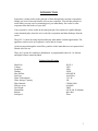
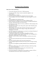
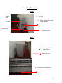
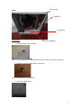
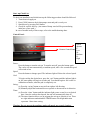
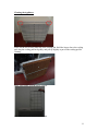
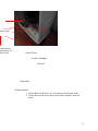
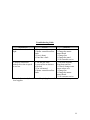
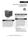
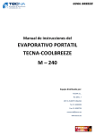
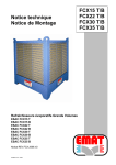
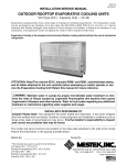
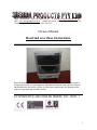
ABN: 76078600450 Free call: 1800630116
Email: [email protected]
Web: www.sierraproducts.com.au Address: P.O.Box 1168, Kangaroo Flat, Vic, 3555
Telephone: (03) 54413388 Fax: (03) 54417833
Owners Manual
Read and save these instructions.
___________________________________________
Read all instructions carefully before setting up and operating this unit. This manual is
designed to provide you with important information needed to setup, operate, maintain
and troubleshoot your cooler. Failure to follow these instructions may damage and/or
impair its operation and void the warranty.
___________________________________________
EVAPORATIVE AIR COOLER MODEL NO.: JH151-1
1
CONTENT
PLEASE READ CAREFULLY AND KEEP THIS INSTRUCTION MANUAL FOR
FUTURE REFERENCE.
SECTION:
PAGE:
Introduction…………………………………………………………………3
Technical Specification……………………………………………………..3
Warning & Safety Information ………………………………………….…4
Parts Description……………………………………………………………5
Assembly Instructions………………………………………………………7
Use & Operation
Connect Water Supply……………………………………………..8
Start-Up Check List………………………………………………..9
Control Panel………………………………………………………9
Remote Control…………………………………………………....10
Cleaning & maintenance………………………………………………….11
Electrical………………………………………………………………….13
Trouble Shooting Guide………………………………………………….14
2
INTRODUCTION
Evaporative cooling works on the principle of heat absorption by moisture evaporation.
Simply put, heat is removed form the air as water evaporates. You feel this principle in
action when you step out of a swimming pool; you immediately feel cooler as water
evaporates from the surface of your skin.
Your evaporative cooler works on the same principle. Hot outside air is pulled through
water-saturated pads, where the air is cooled by evaporation and then discharge from the
cooler.
The jh151-1 is ideal for using in patio and many other indoor/ outdoor applications. The
appliance can be used as an evaporative cooler and air cleaner.
As the air passes through the water filter, particles in the immediate area are captured and
filtered out of the air.
There are 3 speeds for variable air distribution. A programmable timer for 1 to 8 hours
and digital remote control included.
Technical Specifications
Model No.
Voltage
Frequency
Wattage
Max Airflow
Fan Type
Water Consumption
Water Storage Capacity
Filter Material
Effective Area
Net Weight
Dimensions
Remote
Fan Speed
JH151-1
220V
50Hz
300W
6000 M3/H
Axial Flow
3-5 L/H
30L
CELdek 5090
60-80M2
28KG
850 X 480 X 1080mm
Infra Red
Three
3
Warnings & Safety Information
Read and save these instructions.
•
•
•
•
•
•
•
•
•
•
•
•
•
•
•
•
•
•
•
•
•
•
Your cooler will run on 220 Volt AC, 50 HZ current only.
Check the household voltage to ensure it matches the appliance’s rate
specifications.
Can be used indoor or outdoor.
DO NOT operate any product with a damaged electrical cord or plug.
Always unplug the cooler before refilling the water tank through the ‘water fill
door’.
Always unplug the cooler when moving it.
Disconnect the power supply before servicing or cleaning operation.
Remove the power cord from the electrical receptacle by grasping and pulling on
the power cord plug-end only, never from the cord.
DO NOT insert or allow objects to enter any ventilation or exhaust opening as this
may damage the cooler.
DO NOT use the cooler in areas where gasoline, paint or other flammable goods
and objects are stored.
When using the ‘cool’ setting, please check the water tank to ensure it is full.
Operation of this unit on the ‘cool’ setting on a empty tank could result in
damaging the water pump.
DO NOT attempt repair or adjustment to any electrical or mechanical functions of
the cooler, as this may void the warranty.
Verify that the voltage power source matches the appliance electrical
specifications. Improper voltage will burn out the blower/ fan, oscillating and/ or
pump motor windings and will void the warranty.
DO NOT cover the air inlet or outlet on the appliance as this may cause motor
damage.
DO NOT operate with media removed as this will overload and damage the
motor.
DO NOT use this fan with any solid- state speed control device.
Always unplug the appliance from the power source before servicing or moving
the unit.
DO NOT leave the appliance operating unattended for any extended period of
time.
DO NOT let children play with any appliance packaging or plastic bags. Injury
may result from such practice.
Place power cord away from areas where it may cause persons to trip.
When not in use always store in a dry area.
If the unit is damaged or it malfunctions, do not continue to operate it. Refer to
the troubleshoot section and/ or please call customer service.
4
Parts Description
Front:
Control
Panel
Top Panel
Remote Control & Remote
Control Bracket
Air Outlet
Cord Wrap & Power Cord
Water Tank
Stand & Castors
Back:
Air Filter (Dust Filter &
celdek Filter)
Water Fill Door
Connection to Garden Hose
Drain Plug (underneath)
5
Water pump
Inner:
Float Ball
Copper Rod
Accessories:
Overflow Standpipe
1. Remote control and its bracket.
Note: 2 x AAA batteries are required for the remote control, but are not included.
2. Hardware part for Garden Hose Connection
Note: Garden hose are not included.
3. Two pieces Dust Filter
6
Use & Operation
Connect Water Supply:
You can fill up water tank by the following options:
1. Fill fresh water to the tank thru the ‘water fill door’ located on the side panel.
Fill Water Tank As Follows:(a) Plug in the unit onto the “standby” mode.
(b) Press to open the ‘water fill door’ and fill with water manually
(c) You will hear siren for 5 seconds when water reaches the maximum
water level mark.
(d) When water reaches max level, stop filling with water and close the
‘water fill door’.
2. Connect the garden hose to ‘garden hose connection part’ of water inlet
Fill Water Tank As Follows:(a) Turn water supply on. Check for good pressure and flow from float
valve.
(b) When float valve shuts off, check water level. Water level should be
from ½” below top edge of overflow standpipe.
(c) Turn on water and adjust float valve by bending the rod, if required.
(d) Float valve will turn off water supply when water reaches maximum
water level mark.
Note: when COOL mode is turned on, if water level is below minimum
water level mark, the water pump will stop operation; ‘COOL’ LED
indicator will flash.
Water Fill
Door
Connect garden hose
to water in-let.
7
Start- up Check List
To check out installation and initial start-up the following procedure should be followed:
1. Turn electrical supply on
2. Press COOL button to check that pumps starts and pad is evenly wet
3. Start blower by pressing FAN button
4. Check for cool air delivery. (An aroma of damp wood will be present during
initial use of new pads.)
In case of trouble in any of these steps, refer to the troubleshooting chart.
Control Panel:
Speed
options
Remote Control Sensor LLow
MMedium
HHigh
Power:
Press the button to turn the unit on. To turn the unit off, press the button again.
The cooler will start automatically at medium speed, after a few seconds the speed
will switch to low
Speed:
Press the button to change speed. The indicator light will show the selected speed.
Cool:
To begin cooling the desired area, press the ‘cool’ button until the indicate light is
on, the water pump will begin to wet the pad. You should begin to feel cooler air
within three minutes, when the pad is completely wet.
Swing:
(a) Press the ‘swing’ button to start air from right to left direction.
(b) Manually adjust the horizontal louvers upward or downward for air direction.
Timer:
(a) Press the ‘timer’ button until the indicator light comes on and is set to desired
hour. Once the set hour has elapsed, the unit will automatically shut off.
(b) The timer function allows you to program the unit up to 8 hours of use. There
are eight indicators underneath the TIMER button. Each light indication
represents 1 hour timer setting.
Warning: Do not operate the appliance unless all panels are securely in place.
8
Remote Control :
Power
Cool
Timer
Power:
Speed:
Cool:
Swing:
Timer:
Speed
Swing
On/ Off
LOW/ MEDIUM/ HIGH
Control cooling or fan operation
Control the motion of the vertical louvers
Control the timer function for automatic shut off.
9
Cleaning & Maintenance
Changing or Cleaning the Filter/ Pad
Warning: unplug & disconnect the cooler from the power source before attempting
any maintenance or service.
Your cooler should be cleaned at least twice a year, at the beginning of the season and
midway through. But your pads may need to be cleaned more frequently, depending on
local air and water conditions. For instance in areas where mineral content of the water is
high, deposits may build up in the cooler pads, restricting air flow.
Cleaning the Water Tank
To clean the water tank:
• Remove the drain plug located at the bottom of the unit.
• Once the water tank is empty, replace the drain plug, refill the unit and drain it
again.
• Repeat this cleaning weekly to reduce water mineral build up
• Replace the drain plug; refill with fresh water through water- inlet hose, cooler is
ready for use.
TIP: Regular draining (once a week during use) will decrease the water mineral build up
and extend the life of the filter/ pad. Damp a cloth with water and wipe away any water
mineral deposits that appear inside or outside the appliance to extend the serviceable life
& clean appearance of the appliance.
10
Cleaning the Appliance
Screw off the two screws at the top of the cooling pad. Hold the louver above the cooling
pad, drag the cooling pad back gently, and pull up slightly to put off the cooling pad for
cleaning.
Spray water gently over the pad to clean it.
Dust filter net can be cleaned once a week.
11
Water Pump
Connection to
garden hose for
water in-let
Water fill door
Overflow Standpipe
Float ball
Copper Rod
Cleaning Method:
1. Wash off dirt on the float valve and copper rod with damp cloth.
2. Wash off dirt on the water pump and overflow standpipe with soft
brush.
12
Electrical
Electrical wiring diagram
For future reference, the wiring diagram in figure shows rocker switch, three- speed
motor, capacitor and pump.
•
•
•
Switches: POWER; SPEED; SWING & TIMER, are located on the electronic
panel “PCB”.
Class A insulated motor
The blower motor comes equipped with thermal overload protection.
13
Troubleshooting Guide
Malfunction
1. The indicator doesn’t
light
Reason
1. No power
2. Master control board has
faults
3. Fuse is burnt.
4. Panel has a fault
Methods
1. Check the circuit
2. Change the master
control board
3. Change fuse
4. Change the panel.
5. Call customer service.
2. Display normal but
1. The fan gets stuck
1. Check the machine,
without air or the air speed
2. water screen or dust-net
fixing hoop and fan.
is too low.
is blocked
2. Clean or change water
3. Fan is distorted
screen or dust- net.
4. Master control board has 3. Change fan
faults
4. Change the master
control board.
5. Call customer service
Note: the form is only for reference. If any help, please call customer service, or your
local supplier.
14
Sierra Products PTY LTD
A.B.N: 76 078 600 450
A.C.N: 078600450
P.O.Box 1168, Kangaroo Flat Vic 3555
Free Call: 1800630116
Email: [email protected]
Web: www.sierraproducts.com.au
Warranty
The manufacturer warrants that the product is free from defects in the material and factory
workmanship. Subject to the terms of warranty, the manufacturer will repair or replace as its
option, the part of any part thereof, which examination show to be defective for a period of one
(1) year from the date of purchase. Warranty or any other replacement part is limited to the
balance of their original warranty period.
This is sole warranty of the manufacturer, who is not for any obligation, assumed or expressed by
any other persons or person.
The benefit conferred by the warranty and guarantee, are in addition to all other rights and
remedies in respect of such appliance had under the Trade Practices Act (Commonwealth) and
other State and Territory Laws.
Conditions
The warranty is available for the first purchaser only, being the purchaser who purchases without
the intent of reselling for profit.
The structural warranty covers any structural component, which fail to perform to the intended
function due to faulty manufacture or deterioration, within the warranty period.
The warranty does not cover any component parts or equipment used in conjunction with the
cooler which where not supplied by the manufacturer.
15
The warranty does not cover any maintenance or abnormal conditioner of service, including faults
due to connection of impure or deleterious or hard water supplies. The warranty does not cover
damage to the cooler or other damage resulting from acts of god.
The warranty shall not apply to the cooler or part thereof, which in the opinion of the
manufacturer has been subject to accident, alteration, abuse, or misuse or unauthorized repair.
The warranty shall not be offered to any loss suffered by or resulting form the non- operation of
the cooler or part thereof.
Traveling cost incurred for work beyond a 25 km radius, of an authorized Sierra Product P/L
service agent, must be met by the purchaser.
Note: should you require warranty work on your cooler, we recommend that you first contact
Sierra Products P/L, who are best placed to attend to any problem. If, however a service call
reveals no faults with your cooler, you may be charged for the call, even during the warranty
period.
16