1
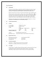
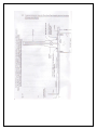
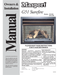
A.B.N 76078600450
A.C.N 078 600 450
P.O.Box 1168
Kangaroo Flat,
Vic
3555
Free Call: 1800 630116
Email: [email protected]
Website: www.sierraproducts.com.au
Sierra 11P Patio Heater
(Propane only)
Sierra 13N Patio Heater
(Natural Gas Only)
AGA Approval No. 4800
Installation and servicing instructions
(After installation, hand these instructions to the consumer.)
Important all installations must conform with relevant statutory regulations and the Australian Gas
Association installation Code AG601. To be installed and serviced by an authorized person.
Contents:
1.0 Introduction
2.0 Technical Specification
2.1 General
2.2 Ignition and Control
2.3 Gas Inlet Connection
3.0 Gas Supply
4.0 Installation Instruction
4.1 Packing
4.2 Assembly of Patio Heaters (Fig. 1)
5.0 Installation and Commissioning
6.0 Installation Lighting Procedure
7.0 Fault Finding
7.1 Control Valve and Pilot Burner
7.2 Piezo Connection
8.0 Short Parts List
8.0A Connection Details
9.0 Servicing
9.1 General Servicing Procedure
9.2 Replacement/ Exchange of Component
Warning1. Do not place articles on or against this appliance.
2. Do not use or store flammable materials near this appliance.
3. Do not spray aerosols in this vicinity of this appliance while it is in operation.
Sierra Patio Heater
1.0
Introduction
The Sierra Cone Patio Heaters combine the benefits of radiant heat to produce overall
comfort conditions to patios, swimming pools and similar outdoor leisure areas. The
heaters have a manual control which combines a flame supervision safety device.
Ignition is activated by pressing a piezo ignition which sparks to light a permanent pilot.
The main burner is then activated by pressing in the lower button
to indicate
for
main burner. Select required main burner flame, either high or low by depressing main
burner flame button. The cone shaped stainless steel emitter radiates warmth, when
outside leisure activities (such as barbeques) are effected by chilly weather conditions.
The heater is for external use only. Always ensure a minimum clearance of 1.5 meters
both sideways and 400mm above from flammable materials.
2.0
Technical Specifications
2.1
General
Overall Height
Overall Width
Weight
2380mm (7ft 9-1/2in)
970mm (3ft 2in)
32 kg
Nominal Input Burner Pressure
MJ/HR
kPa
46.8
0.75
41.4
2.75
Natural Gas Model 13N
Propane Gas Model 11P
Control
Main Burner Type
2.2
Sit 500 Simplosit Control Valve
Pressed steel venturi; vertical position with cast iron top.
Ignition and Control
Push button piezo ignition
Flame supervision valve
Permanent pilot
2.3
Injector Size
MM
3.30
1.90
type Vernitron 66212/002
type Sit 500
type 27A4G
Gas Inlet Connection
Natural Gas. ½” BSP connection on the inlet to the regulator.
Propane Gas. 3/8” BSP on the inlet to the gas control valve.
3.0
Gas Supply
If no gas supply is available, contact your local gas utility to arrange provision of a meter.
Existing meters should be checked to ensure adequate capacity to cope with the
additional gas supply required. If in doubt contact your local gas supply authority.
3.0
Gas Supply continued.
Gas supply piping should be of an adequate size. Refer section 4 of AG601. Particular
attention should be paid to section 4.11 of AG601 concerning the location and depth of
cover for consumer piping.
The complete installation must be tested for soundness as per section 2.6 of AG601.
4.0
Installation Instructions
4.1
Packing
The patio heater will arrive packed in two cartons which will contain ready to assemble
parts i.e.:a. Reflector
b. Cone shaped emitter
c. Support stand base assembly
4.2
Assembly of Patio Heater (Fig. 1)
1. Stand the base assembly (e) on a flat even surface.
2. Remove bottom cover on assembly (b) by unscrewing 3 x M5 screws. This will expose
the inner frame and gas regulator connection.
3. Secure the reflector assembly (a) and cowling to the cone shaped emitter with the 3 x
M8 thumbscrew.
5.0
Installation and Commissioning
1. Locate patio heater in final position on patio or leisure area. (Confer with customer,
purchaser or user.
Warning- ensure minimum clearance from flammable material both 400mm above
and sideways of 1.5 meters (4ft 6in) this appliance is for external use only.
2. Traditional Model
The base (e) must be firmly secured by means of wrag bolts or similar into concrete
beneath paving slabs through the three holes in the base.
3. It is recommended that an isolating valve is fitted inside the base.
4. Connect a continuous run or ½” copper pipe between the regulator inlet (Natural Gas)
or gas valve inlet (Propane Gas) and the isolating valve in the base.
5. Connect gas supply to the isolating valve.
6. Ensure that all gas connections are tightened.
7. Turn on manometer (for initial lighting and testing). Test all gas connections for
soundness.
8. Connect manometer to pressure test nipple located inside control cover assembly (b)
above Sit 500 Simplosit Valve.
9. Ignite patio heater (refer to lighting procedure section 6)
10. Natural Gas
The governor is located under the control valve. Check the setting corresponds with the
data plate information. To adjust setting pressure loosen the locknut. Adjust regulator
clockwise to increase pressure- anticlockwise to decrease pressure. When correct
pressure is achieved tighten the locknut to prevent accidental changes in the settings.
Propane Gas
Check that the setting corresponds with the data plate information. This pressure is
adjusted at the supply regulator and should be tested when other appliances on the supply
line (if fitted) are operating.
11. Test all gas connections for soundness.
12. Turn off heater, remove manometer and replace test nipple screw.
Advise the user, or purchaser that for continued efficient and safe operation of the heater,
it is important that adequate servicing is carried out at intervals recommended by the
local gas utility. Demonstrate to the user how to light the heater and then hand over the
users instructions.
6.0
Initial Lighting Procedure.
1. Slide open control cover door.
Operating instruction- Natural Gas
1. Turn gas cock on.
2. Push lower button fully in
at the same time operate igniter button, until pilot flame
lights, continue to hold button in for approximately 15 seconds. (1-2 minutes may be
required.)
3. Release lower button
Release lower button
to indicate
to indicate
for pilot only.
for main burner.
4. Maximum flame release top button fully
to indicate
.
5. Minimum flame release top button halfway
to indicate
6. Close the gas cock to turn off the main burner and the pilot.
Operating instructions- Propane Gas
1. Turn on gas cylinder valve.
2. Push lower button fully in
at the same time operate igniter button until pilot flame
lights, continue to hold button in for approximately 15 seconds. (1-2 minutes may be
required.)
3. Release lower button
Release lower button
to indicate
to indicate
for pilot only.
for main burner.
4. Maximum flame release top button fully
to indicate
.
5. Minimum flame push top button halfway
to indicate
6. Turn “off” from cylinder valve by turning clockwise by hand.
7.0
Fault Finding
7.1
Control Valve and Pilot Burner.
Pilot Flame goes out.
1. Check gas supply has not been turned “off”
2. Check pilot flame adjustment on the side of control valve. Remove cover screw, adjust
inner screw anti clockwise to give 30mm long flame (see Fig. 3 and 4) whilst holding
control knob depressed in pilot position if necessary).
3. Check thermocouple connections on control valve.
Remedy:
Replace
Thermocouple
Thermo- mag assembly for Sit 500 Valve.
7.2
Part Number
2894
2787
Piezo Ignition
No spark.
1. Check that connections are sound on lead ends.
2. Check that piezo igniter is creating sufficient spark when “red” button is pushed and
that spark gap is 5mm +/- 0.5mm (3/16in.) (See Fig. 3)
Remedy
Replace
Lead
Peizo
Electrode
Part Number
4540
4542
4543
Note: If heater cannot be adjusted to perform satisfactorily, contact your state service
agent or Sierra Product Pty Ltd.
8.0
Short Parts List
Appliance name and model Sierra Patio Heater 13N
Appliance name and model Sierra Patio Heater 11P
Manufacturer:
Sierra Space Heating Ltd
Australian Agent:
Sierra Products Pty Ltd
P.O.Box 1168
Kangaroo Flat Vic
3555
A.C.N No. 078600450
Key No.
1
1
Description
Main injector Natural Gas 3.30mm
Main injector Propane Gas 1.90mm
No. Off
1
1
Code No.
1896
1895
2
2
3
4
5
6
7
8
9
Pilot injector Natural Gas No. 7215
Pilot injector Propane Gas No. 4209
Piezo Electrode Lead 400mm
Ignition Electrode
Piezo Igniter 66212/002
Thermomag for Sit 500 Valve
Thermocouple 2800B060
Burner Complete
Pilot Burner 27 Series
1
1
1
1
1
1
1
1
1
2993
2992
4540
4543
4542
2787
2894
1890
2831
8.0A
Conversion Detail.
Sierra Traditional and Standard Model Patio Heaters may be converted between natural
gas and propane operation. Conversion involves changing to the correct injector and pilot
injector. (Refer to part numbers)
Part numbers traditional and standard patio heaters.
Conversion to
11P
13N
For Use on
Propane (G31)
Natural (G20)
Injector
1895
1896
Pilot injector
2992
2993
Data badge
3346
3347
Injector Dia (mm)
1.90
3.30
G.C. MJ/HR
41.4
46.8
Gas Pressure (KPA)
2.75
0.75
9.0
Servicing
Important Note:
To be serviced only by an authorized person.
9.1
General Servicing Procedure
1. Turn off main gas at service cock.
2. Remove reflector assembly (a) by unscrewing 3 x M8 thumbscrews.
3. Unscrew the M8 hex set screw (located in the center of the cone shaped emitter) and
remove emitter for examination and cleaning. Wire brush inside and out of perforated
emitter cone to remove any deposits.
4. Remove wind shield guard to expose the main burner assembly and pilot burner
assembly examine, clean, or replace (see below).
Main Injector
Pilot Burner
Piezo Igniter lead
Ignition Electrode
Thermocouple
5. Refer to 8.0 spares list for part codes.
Reassembly is a reverse of the above procedure.
The Sierra Heater must be tested and commissioned for operation and soundness as
described in 5.0 Installation and commissioning
9.2
Replacement/ Exchange of components
1. Main injector
Carry out general servicing 1-4
Unscrew injector from adaptor/ burner
2. Pilot Injector
Carry out general servicing 1-4.
Unscrew nut securing thermocouple to pilot bracket/ assembly.
Pull off ignition lead to electrode.
Disconnect pilot supply pipe from pilot injector.
Remove two screws securing pilot assembly to support bracket.
Unscrew pilot injector from pilot burner.
Reassemble in reverse order.
3. Piezo Igniter Lead.
Carry out general servicing 1-4
Pull off ignition lead from Piezo igniter and electrode, cut off tie securing lead to pilot
supply and thermocouple. Fit new ignition lead and secure with new cable tie.
4. Ignition Electrode
Carry out general servicing 1-4.
Unscrew nut securing thermocouple to pilot bracket/ assembly.
Pull off ignition lead to electrode.
Remove screw securing electrode to pilot assembly and lift out electrode.
Fit new electrode, check spark gap is 5mm +/- 0.5mm (3/16in)/ (See Fig. 3)
5. Thermocouple
Carry out general servicing 1-4.
Unscrew nut securing thermocouple to pilot bracket/ assembly and F.S.D
Cut off cable tie securing ignition lead to thermocouple.
Note: on reassembly fit new cable tie.
6. Thermomag Unit for Sit 500 F.S.D
Unscrew nut securing thermocouple to rear of unit.
Unscrew thermomag unit from Sit 500 valve.
After reassembly check Sit 500 for gas soundness.
7. Piezo Igniter
Pull off ignition lead from rear of igniter.
Unscrew nut securing piezo igniter to support bracket.
8. Main Burner
Carry out general servicing 1-4.
Remove two screws securing burner to injector assembly and burner pan.
Warranty
Guarantees all products
supplied against any manufacturing defect for a twelve month period from date of sale.
The Warranty does not cover the following:
1. Faults/ Failure caused by misuse, neglect or faulty adjustments by the user.
2. Failures resulting from not using the product in accordance with the operating instruction
manual.
3. Failure as a result of sudden impact.
4. Failure which had occurred from normal fair, wear and tear.
5. Any unit which has been serviced or repaired, taken apart of tampered with by any person not
being a qualified installer.
6. The benefits conferred by this warranty and guarantee are in addition to all other rights and
remedies in respect of such appliance has under the Trade Practices Act (Commonwealth) and
other state and territory laws.
Warning
This Emitter is coated with a protective
oil.
Upon lighting this will burn off and there
will be some initial smoke.
Ensure adequate ventilation.