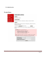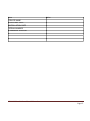
1
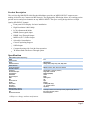
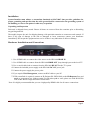
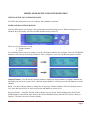
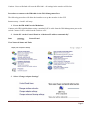
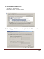
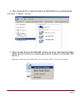
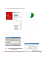
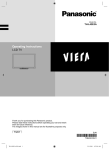
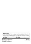
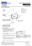
HD-1600 Single Input MPEG4 DVB-T HD Encoder/Modulator User Guide and Install Manual Table of Contents Safety Precautions..........................................................................................................................................2 Package Contents ...........................................................................................................................................2 Product Description........................................................................................................................................3 Specification...................................................................................................................................................3 Installation......................................................................................................................................................4 Modulator Setup and Configuration ..............................................................................................................5 Web Management via Port .............................................................................................................................6 Encoder Programming and Setup via GUI Interface: ....................................................................................9 Common Setup.............................................................................................................................................10 Attenuation...................................................................................................................................................10 RF Setup.......................................................................................................................................................11 Encoder Setup ..............................................................................................................................................12 Network Configuration ................................................................................................................................13 Administration .............................................................................................................................................14 Saving your configuration files....................................................................................................................15 HD-1600 User Guide and Install Manual Page 1 Safety Precautions The presence of this symbol is to alert the installer and user to the presence of uninsulated dangerous voltages within the product’s enclosure that may be of sufficient magnitude to produce a risk of electric shock. TO REDUCE THE RISK OF FIRE OR ELECTRIC SHOCK, DO NOT EXPOSE THIS DEVICE TO RAIN OR MOISTURE. DO NOT OPEN THE UNIT. REFER SERVICING TO QUALIFIED PERSONNEL ONLY. DO NOT apply power to the unit until all connections have been made, all components have been installed and all wiring has been properly terminated. DO NOT terminate, change or uninstall any wiring without first disconnecting the unit’s power adapter from the device. This device is supplied with the appropriately rated power supply. The use of any other power supply could cause damage and invalidate the manufacturer’s warranty. DO NOT connect the power cord to the device if the power cord is damaged. DO NOT cut the power cord. DO NOT plug the power cord into an AC outlet until all cables and connections to the device have been properly connected. The device should be installed in an environment consistent with its operating temperature specifications. Placement next to heating devices and ducts is to be avoided as doing so may cause damage. The device should not be placed in areas of high humidity. DO NOT cover any of the device’s ventilation openings. DO NOT cover or obstruct the device’s fan or fan openings. If the device has been in a cold environment allow it to warm to room temperature for at least 2 hours before connecting to an AC outlet. Package Contents This package contains: One HD-1600 Encoder / Modulator* One power supply One installation / configuration manual Inspect the package before starting installation to ensure there is no damage and all supplied contents are present. Contact your distributor or dealer should the device be damaged or package contents are incomplete. HD-1600 User Guide and Install Manual Page 2 Product Description The resi-linx digi-MOD HD-1600 Encoder/Modulator provides an MPEG4 DVB-T output stream making it ideal for any Commercial RF Network. The high quality HD design allows for watching action packed movies and sports channels on any MPEG4 HDTV. The space saving design delivers a High Quality HD DVB-T channel. Front panel LCD Display for basic installation High Resolution 1080i/1080p LCN Adjustment & Mode HDMI (unencrypted) input HDMI Loop Through Output MPEG4 (AVC) Video Output Selectable Constellation Closed Captioning Support 85dB Output Compact housing with Cool & silent operation IR Return Path with Power Through option Specification VIDEO INPUTS (Video by Priority) HDMI Video Encoder Mode Video Resolutions AUDIO Encoder Audio Compression RF DVB-T Support Frequency RF Channel Output Constellation Bandwidth RF Level Output MER FEC Guard Interval OFDM Attenuation RF Output Audio Input Management / Control Front Panel LCD Control GUI Password Protected 1.4v MPEG-4(AVC) 1080p, 1080i, 720p, 576p, 576i, 480p, 480i MPEG-1 Layer II, AAC, AC-3 Pass Through Channel Plan - Varies by Country Single DVB-T Channel 64QAM (16QAM) 7 MHz 85dB 36dB Typical 7/8 1/32 8K (2K) 1-20dB (1dB steps) "F" - Female 75 ohm L/R (RCA) RF Output Channel and LCN Adjustment (Up/Down/OK Buttons) IE9, Firefox, Chrome, Safari Front Panel, GUI **Subject to change without notifications HD-1600 User Guide and Install Manual Page 3 Installation System Installer must adhere to Australian Standards AS1367:2007 that provides guidelines for proper grounding and specifies that the cable ground shall be connected to the grounding system of the building, as close to the point of cable entry as possible. Unpacking and Inspection Each unit is shipped factory tested. Ensure all items are removed from the container prior to discarding any packing material. Thoroughly inspect the unit for shipping damage with particular attention to connectors and controls. If there is any sign of damage to the unit or damaged or loose connectors contact your distributor immediately. Do not put the equipment into service if there is any indication of defect or damage. Hardware Installations and Connections 1. Use a HDMI cable to connect the video source to the HD-1600 HDMI IN. 2. Use a HDMI cable to connect from the HD-1600 HDMI OUT (loop through) port to the local TV. 3. Use a coaxial cable lead to connect from the HD-1600 RF OUT to the TV system. 4. Connect the included power supply to the HD-1600 DC 12V power jack 5. Connect the power supply the power point 6. If you require Web Management, connect an RJ45 cable to your PC 7. IF IR return Path is required, connect an IR Emitter (RL-IR700/800) to the IR Repeater Port and attach to your source you wish to control. For IR return path to work, please use with RL-RF380 VDU & RL-RF210 Target and follow instructions Note: It is highly recommended that you use a high quality HDMI cable for all source connections. HD-1600 User Guide and Install Manual Page 4 MODULATOR SETUP AND CONFIGURATION INITIAL SETUP TO FACTORY DEFAULT The HD-1600 front panel is used to configure the modulator as desired MODULATOR CONFIGURATION Once the HD-1600 is powered up it will go through an initial booting process. When booting process is finished, the LCD display will show default channel number and LCN There are two parameters to setup 1. Channel number 2. LCN For switching between the two settings, press the OK Button until the arrow flashes. Press the UP/DOWN buttons to select the desired setup parameters. Once completed – press the OK Button again to confirm Output Channel – Use the Scroll Up/Down button to change the output channel. Available channels are depending on your local system. Once a desired output channel is selected, press the OK Button to set the channel LCN – Use the Up/Down button to change the LCN (Logic Channel Number) The LCN default value is 101. Once the desired LCN is selected, press the OK Button to set the LCN Reset to Default – Turn OFF the HD-1600 for button on rear of unit. While holding down the UP and DOWN buttons, turn ON the unit. Release the UP and DOWN buttons when the LCD shows “Reset to Default”. The unit will reset to factory default. HD-1600 User Guide and Install Manual Page 5 Caution – Reset to Default will reset the HD-1600 – all settings in the encoder will be lost. Procedure to connect to the HD-1600 via the Web Management Port The following procedure will allow the installer to set up the encoder via the GUI Intranet setup – closed LAN setup 1. Power the HD-1600 Encoder/Modulator Connect each HD-1600 Modulator using a standard CAT5e cable from the Web Management port to the switch. Connect CAT5e cable from the switch to a PC 2. Set the PC via the Control /Panel to “Obtain an IP address automatically” Start Control Panel View Network Status and Tasks 3. Select “Change Adaptor Settings” HD-1600 User Guide and Install Manual Page 6 4. Select Local Area Connection Icon Then right click – Select properties Internet Protocol Version 4 (TCP/IPv4) Properties 5. Select “Obtain an IP address automatically” & “Obtain DNS server address automatically” HD-1600 User Guide and Install Manual Page 7 6. After setting the PC to obtain IP address & Obtain DNS server automatically Select Start – Computer – Network resi-linx 001 resi-linx 002 7. After selecting Network the HD-1600 will show up on the right hand side under Media Devices. Each device will show up by Device Address. (resi-linx 001, 002, 003 etc) Right click on the icon for the HD-1600 you want to setup. Select “View device webpage” HD-1600 User Guide and Install Manual Page 8 8. Welcome page will be displayed as shown resi-linx 001 HD-1600 9. Select the Common Setup tab. User will be presented with encoders “Authentication Required” screen 10. Enter User Name and Password. User Name: admin HD-1600 User Guide and Install Manual Page 9 Password: Admin123 11. Common Setup 12. Attenuation Adjust the attenuator on the rear of the HD-1600 to desired level. HD-1600 User Guide and Install Manual Page 10 13. RF Setup resi-linx HD-1600 User Guide and Install Manual Page 11 14. Encoder Setup resi-linx HD-1600 User Guide and Install Manual Page 12 15. Network Setup resi-linx HD-1600 User Guide and Install Manual Page 13 16. Administration Product Notes: HD-1600 User Guide and Install Manual Page 14 Item Value DEVICE NAME PURCHASE DATE INSTALLATION DATE SERIAL NUMBER FIRMWARE VERSION HD-1600 User Guide and Install Manual Page 15 HD-1600 User Guide and Install Manual Page 16