Transcript
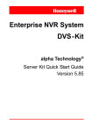
Hard Wired IR Range
RL-IR100
by
resi-linxTM IR KIT
INSTALLATION MANUAL
A IR LED
B IR Emitter outputs
Remote
Control
C 12V DC input
D Target input
E Power LED
D
E
Flat IR
Target
Junction Box
A
Pay TV
B
C
12V DC 500mA
Power Adaptor
Double
Emitter
DVD
Hardware Connection
1. Connect IR Emitter to the output on the side of the
Junction Box B . Place the emitter head 10mm to
either side of the IR receiver on the Audio/Video source
(depending on environmental conditions).
Additional IR Emitters RL-IR700 / RL-IR800 can be
purchased if required.
2. Connect Flat IR Target green connector directly into target
input on Junction Box D .
Target Wiring
White stripe
12V+
Centre
IR
Black
GND
3. Connect the 12V DC 500mA power pack to the power
input on the Junction Box C . Check the green LED E
is illuminated.
Frequency Range
4. Place the target in a position to receive IR commands.
LED indicator on both IR Target, and Junction Box A
illuminate briefly upon receipt of IR command.
20-200kHz
Power Input
12V DC 500mA Switch Mode
Maximum Target reception distance
Up to 8 metres
Target cable length
1.8 metres
(Refer to www.resi-linx.com for further information).
WARRANTY
VComm Pty Ltd states that the warrant that the customer can rely on is that
provided by the manufacturer. In the event of any warranty claim please
contact us and we will forward it to the manufacturer. The manufacturer will
then determine the extent of their liability. This expressly negates, to the
extent possible by Australian law, any warranty reliance on VCOMM Pty Ltd.
Vcomm Pty Ltd
ACN: 091 281 524
ABN: 99 091 281 524
www.resi-linx.com