1
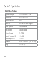
SVA 1
Single-mode Fiber Optic Variable
Attenuator
User’s Guide
Test & Inspection
A
SVA 1
Single-mode Fiber Optic Variable
Attenuator
User’s Guide
Test & Inspection
© 2003, AFL Telecommunications, all rights reserved. SVA1-00-1000 Revision C, 9.15.05
Specifications are subject to change without notice.
C
Limited Warranty
One Year Limited Warranty
All Noyes products are warranted against
defective material and workmanship for a
period of one year from the date of shipment
to the original customer. Any product found to
be defective within the warranty period will be
repaired or replaced by Noyes. In no case will
Noyes liabilities exceed the original purchase
price of the product.
Exclusions
The warranty on your equipment shall not apply
to defects resulting from the following:
•
Unauthorized repair or modification
•
Misuse, negligence, or accident
CE Information
These instruments have been
designed and tested to comply
with the relevant sections of
D
any applicable specifications including full
compliance with all essential requirements of
all applicable EU Directives.
Returning Equipment
To return equipment, please contact Noyes
to obtain additional information and a Service
Request (S.R.) number. To allow us to serve
you more efficiently, please include a brief
description specifying the reasons for the
return of the equipment.
AFL Telecommunications
Noyes Test & Inspection
16 Eastgate Park Road
Belmont, NH 03220
Phone: 800-321-5298
603-528-7780
Fax:
603-528-2025
Contents
Safety Information .......................................................................II
Section 1: General Information
Contacting Noyes Customer Service ............................................1
Unpacking and Inspection ...........................................................1
Feature Overview ........................................................................2
Recommended Accessories.........................................................2
Section 2: Functional Description
SVA 1 Front Panel .......................................................................3
Section 3: Applications
System Margin Test ....................................................................4
step I - measure optical power of the transmitter ......................4
step II - insert SVA 1 between transmitter and receiver .............6
step III - measure system margin..............................................7
Receiver Sensitivity Test ..............................................................8
Section 4: Maintenance
Cleaning the Optical Ports ...........................................................9
Section 5: Specifications
SVA 1 Specifications ...................................................................10
I
Safety Information
!
CAUTION! To avoid serious eye injury, never look directly into the optical outputs of fiber
optic network equipment, test equipment, patch cords, or test jumpers. Refer to your
company’s safety procedures when working with optical systems.
!
NOTICE! An SVA 1 Single-mode Variable Attenuator contains no user serviceable
parts. Except for cleaning optical ports, this instrument must be returned to Noyes or
authorized agents for repair.
IMPORTANT! Proper care in handling should be taken when using any precision
optical test equipment. Scratched or contaminated optical connectors can impact the
performance of the instrument. It is important to keep the dust caps in place when the
unit is not being used.
II
Section 1: General Information
Thank you for purchasing a Noyes SVA 1 Single-mode Variable Attenuator. The purpose of this
user’s guide is to explain how to use and maintain this instrument. Please check our web site
at www.AFLtele.com (click on Products > Noyes Test & Inspection) for updates to this
manual and additional application information. If you have any questions about your instrument
and recommended accessories, or if you need technical or sales support, please contact Noyes
Customer Service.
Contacting Noyes Customer Service
You may call Noyes Customer Service between 8 a.m. and 5 p.m., United States Eastern Time,
as follows:
Phone:
800-321-5298
603-528-7780
Fax:
603-528-2025
Web:
www.AFLtele.com (click on Products > Noyes Test & Inspection)
Unpacking and Inspection
This instrument has been carefully packed in accordance with standard shipping procedures.
Examine the equipment for damage that may have occurred during shipment. If you find any
damage, please contact Noyes.
1
Feature Overview
The SVA 1 Single-mode Variable Attenuator advances fiber optic field testing by offering superior
performance in a low cost hand-held package. Utilizing a simplified, industry accepted attenuation
technique, the innovative design of the SVA 1 offers superior resolution across the entire 60 dB
dynamic range. Intended for field testing during installation, new equipment turn-ups, or routine
maintenance, the SVA 1 is a complete, easy to use attenuator. Its unique features allow bidirectional
signal transmission with no loss penalty.
The SVA 1 is available with a variety of connectors and reflectance options (better than 60 dB).
With only two adjustments, COARSE and FINE, the SVA 1 is simple to understand and operate.
The SVA 1 is suited for all single-mode applications including Telco, LANs, WANs, Video, and
CATV.
Recommended Accessories
2
You will need fiber optic test jumpers to connect your SVA 1 to the system under test. Test
jumpers must have the same core and cladding size as the fiber under test. Test jumpers require
the appropriate connectors on each end to match to the system’s connector style and the output
connector on the SVA 1. Test cables and jumpers with a variety of lengths and connector styles
are available from Noyes.
A supply of optical cleaning pads and isopropyl alcohol or a connector-cleaning cartridge is
recommended to clean the optical connectors on your SVA 1 and test cables. A supply of fiber
optic cleaning swabs or a can of filtered compressed air is recommended for cleaning connector
adapters. Noyes recommends using our new non-flammable, environmentally safe Fiber Optic
Cleaning solution and molded dual-head connector end-face cleaning tips.
Section 2: Functional Description
SVA 1 Front Panel
Input/Output port us e d to c o nne c t t he
SVA 1 to the receiver or
transmitter end of the
system under test
Fine adjustment knob used for fine attenuation
adjustment (0 to 10 dB
nominal)
Display windows indicate the attenuation
adjustment being between
minimum or maximum
SVA 1
SINGLEMODE
ATTENUATOR
FINE
COURSE
10 dB
60 dB
MAX
MAX
MIN
MIN
NOYES
Input/Output port us e d to c o nne c t t he
SVA 1 to the receiver or
transmitter end of the
system under test
Coarse adjustment
knob - used for course
adjustments (0 to 60 dB
nominal)
Display windows indicate the attenuation
adjustment being between
minimum or maximum
FIBER SYSTEMS
3
Section 3: Applications
System Margin Test
The SVA 1 is used effectively during system margin measurements. To measure the system
margin, first measure the absolute power in dBm of the transmitter with an optical power meter
and record the measured NON-ATTENUATED power level.
step I - measure optical power of the transmitter
In the following procedures the Noyes OPM 5 optical power meter is used to perform
measurements.
1 Turn on the OPM 5 optical power meter (refer to Figure, page 5).
2 Select the appropriate fiber optic test jumper.
Note: The fiber type of this jumper must be the same as the fiber type normally connected
to the output being measured.
3 Mount the appropriate adapter cap on the OPM 5 optical input. This adapter cap must match
the connector on the end of the test jumper you will connect to the OPM 5.
4 Connect one end of the test jumper to the OPM 5 (adapter cap) and the other end to the optical
output to be measured.
5 Press the [λ] key to select the calibrated wavelength that matches the nominal wavelength
of the source being measured.
4
6 Press the [dB/dBm] key to display power in dBm - this is the measured NON-ATTENUATED
power level. If using a power meter other then OPM 5 or OPM 4, record this measurement.
7 Press and hold the REF key until “HELD” appears to set the reference level at the current
wavelength. The OPM 5 should display “0 dB” ±0.05 dB.
3 adapter cap
transmit jumper
NOYES
Serial
Pwr
FIBER SYSTEMS
OPTICAL POWER METER
1300
OPM ACTIVE
AUTO OFF
-10.00
network
transmitter
µW
6
nm
dBm
7
Set
dB
dBm
Ref
network
receiver
5
Print
Store
Recall
Clear
1
On
Off
OPM 5
5
Note: The high return isolation of the attenuator assures that the transmitter is not adversely
affected by reflected power.
step II - insert SVA 1 between transmitter and receiver
8 Insert the SVA 1 attenuator between the transmitter and receiver.
9 Increase the attenuation by turning the Fine or Course knobs until the Bit Error Rate exceeds
the specified minimum rate.
network
transmitter
network
receiver
transmit jumper
receive jumper
SVA 1
6
step III - measure system margin
10 Disconnect the receive jumper at the receiver and connect it to the OPM 5 optical power meter.
The ATTENUATED power level will automatically be displayed. In diagram below, the OPM 5
indicates an additional 7 dB of loss that is available before system failure. Changing the display
reading to dBm gives the absolute level at which system failure occurred. This level should be
within the receiver manufacturer specifications.
!!! If using an optical power meter other then OPM 5 or OPM 4, calculate the system margin
by subtracting the NON-ATTENUATED power level from the ATTENUATED power level.
Note: Adjusted attenuation is wavelength dependent. Confirm loss levels when changing light
source.
transmit jumper
receive jumper
network
transmitter
network
receiver
7.00 dB
SVA 1
OPM 5
7
Receiver Sensitivity Test
If the power measured by an optical power meter is too high or “hot” for the receiver, perform
the following steps:
1 Insert the SVA 1 attenuator between the transmitter and receiver.
2 Increase the attenuation by turning the Fine or Course knobs until the system operates
properly.
3 Connect the optical power meter to the SVA 1 to measure the attenuated power.
4 The loss displayed on the optical power meter is the attenuation required to bring the system
within specifications of the receiver.
Note: A fixed attenuator of the appropriate value can then be permanently inserted in the
system. This process is referred to as “padding the system”.
8
Section 4: Maintenance
Cleaning the Optical Ports
It is important to keep all optical connections and surfaces free from dirt, oils, or other
contamination to ensure proper operation. Scratched or contaminated connectors can reduce
system performance.
Optical ports must be kept free from dirt or other contaminates to ensure accurate measurements
and operation. A supply of optical cleaning pads and isopropyl alcohol is recommended to clean
the optical ports.
Noyes recommends using our new non-flammable, environmentally safe Fiber Optic Cleaning
solution and molded dual-head connector end-face cleaning tips.
It is important to keep the dust cap in place when the unit is not being used.
9
Section 5: Specifications
SVA 1 Specifications
10
Specified Wavelengths
1310 nm & 1550 nm ± 30 nm
Insertion Loss
≤ 1.5 dB @ 1310 nm
Minimum Attenuation
60 dB
Return Loss
50 dB (≥60 dB optional - angled FC)
Coarse Adjustment
0 to 60 dB nominal
Fine Adjustment
0 to 10 dB nominal
Standard Connector
FC, ST, SC
Operating Temperature (°C)
-10 to +55
Storage Temperature (°C)
-30 to 60
Dimensions
5.5” H x 2.75” W x 1.5” D (14 x 7 x 3.8 cm)
Weight
0.4 lb. (0.2 kg)
Thank you for choosing Noyes Test & Inspection
� �� � �
16 Eastgate Park Road
���
Belmont, NH 03220
����
Phone: 800-321-5298
� � �� � � � � �
603-528-7780
Fax: 603-528-2025
www.AFLtele.com > Products > Noyes Test & Inspection
Test & Inspection