1
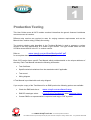
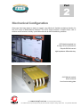
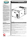
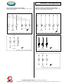
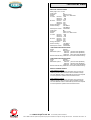
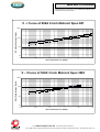
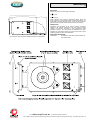
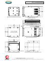
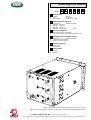
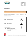
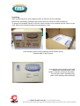
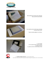
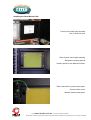
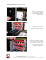
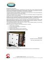
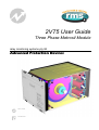
2V75 User Guide Three Phase Metrosil Module relay monitoring systems pty ltd Advanced Protection Devices User Guide Test Manual 2V75 User Guide About This Manual This User Guide covers all 2V75 modules manufactured from May 2003. Earlier modules do not necessarily incorporate all the features described. Our policy of continuous may means that extra features & functionality may have been added. The 2V75 User Guide is designed as a generic document to describe the common operating parameters for all relays built on this platform. Some relay applications are described but for specific model information the individual “K” number Product / Test manuals should be consulted. The copyright and other intellectual property rights in this document, and in any model or article produced from it (and including any Registered or unregistered design rights) are the property of Relay Monitoring Systems Pty Ltd. No part of this document shall be reproduced or modified or stored in another form, in any data retrieval system, without the permission of Relay Monitoring Systems Pty Ltd, nor shall any model or article be reproduced from this document without consent from Relay Monitoring Systems Pty Ltd. While the information and guidance given in this document is believed to be correct, no liability shall be accepted for any loss or damage caused by any error or omission, whether such error or omission is the result of negligence or any other cause. Any and all such liability is disclaimed. Contact Us © Relay Monitoring Systems Pty Ltd 2001-2008 6 Anzed Court • Mulgrave 3170 • AUSTRALIA Phone 61 3 9561 0266 • Fax 61 3 9561 0277 Email [email protected] • Web www.rmspl.com.au To download a PDF version of this guide: http://www.rmspl.com.au/userguide/2v75_user_guide.pdf To download the model specific Test Manual: http://www.rmspl.com.au/search.asp How this guide is organised This guide is divided into five parts: Part 1 Overview About this Manual Contents Production Testing Part 2 Mechanical Configuration Part 3 Technical Bulletin Part 4 Installation Safety Unpacking Installing the Panel Mount Plate Installing the Metrosil Module Adjusting the Stabilizing Resistors Storage & Handling Equipment Connection Part 5 Maintenance Mechanical Inspection Test Intervals Defect Report Form Visit www.rmspl.com.au for the latest product information. Due to RMS continuous product improvement policy this information is subject to change without notice. 2V75_Guide/Iss B/21/08/08 Part 1 Production Testing This User Guide covers all 2V75 module versions & describes the generic features & attributes common across all versions. Different relay versions are required to cater for varying customer requirements such as the Metrosil size, resistor rating (If fitted) & mounting. The product ordering code described in the Technical Bulletin is used to generate a unique version of the relay specification & is called a type number. The type number takes the form 2V75Kxx where the Kxx is the “K” or version number. www.rmspl.com.au/handbookparta3.pdf Refer to: for a complete description of the RMS “K” number system. Each 2V75 version has a specific Test Manual which provides details on the unique attributes of the relay. Each Test Manual includes the following information: • Test Certificate • Specific technical variations from the standard model if applicable • Test record • Wiring diagram A Test Manual is provided with each relay shipped. If you require a copy of the Test Manual for an RMS product the following options are available: • Check the RMS web site at: www.rmspl.com.au/search.asp • RMS CD catalogue select: List all Product/Test Manuals under Technical Library • Contact RMS or a representative & request a hard copy or PDF by email. Visit www.rmspl.com.au for the latest product information. Due to RMS continuous product improvement policy this information is subject to change without notice. 2V75_Guide/Iss B/21/08/08 Part 2 Mechanical Configuration Great care has been taken to design a rugged, cost effective & flexible mechanical solution for the 2V75 range of RMS Metrosil modules. The 2V75 range provides a compact flush, rack or surface mount solution for bulky 3 pole Metrosils with & without stabilizing resistors. 2V75 Module depicted in a 4U high 19 inch rack next to a Reyrolle DAD-N numeric high impedance differential relay. 2V75 Metrosil module shown removed from front mounting plate Visit www.rmspl.com.au for the latest product information. Due to RMS continuous product improvement policy this information is subject to change without notice. 2V75_Guide/Iss B/21/08/08 Part 3 Technical Bulletin The detailed technical attributes, functional description & performance specifications for the 2V75 are described in the attached Technical Bulletin. For the most up to date version go to: www.rmspl.com.au/handbook/2v75.htm For any specific attributes of a particular version refer to the Test Manual for that type (K) number. The order of precedence for technical information is as follows: • • • Test Manual Technical Bulletin User Guide Visit www.rmspl.com.au for the latest product information. Due to RMS continuous product improvement policy this information is subject to change without notice. 2V75_Guide/Iss B/21/08/08 2V75 Technical Bulletin Metrosil / Resistor Module Features Compact & rugged construction Fully insulated module Suitable for high impedance differential BUS protection schemes Suitable for restricted earth fault REF protection schemes High energy absorption rating Pre-wired with heavy duty stud or screw terminals Specify 3 or 6 inch Metrosils Specify 1 phase or 3 phase Optional stabilizing resistors with convective cooling ports Specify nominal value of adjustable stabilizing resistors Specify stabilizing resistor power rating Rear swing door access for stabilizing resistor adjustment Heavy duty construction comprising aluminium side plates to ensure excellent mechanical & thermal performance 2V75 depicted in a size 8 rack or flush mount module Operation Application The 2V75 Metrosil module is designed for application with high impedance differential protection schemes. An external Metrosil unit having a nonlinear resistance characteristic is required for each phase element to limit the peak voltage appearing across the secondary differential circuits under internal fault conditions. The type of Metrosil characteristic required is dependant on the relay setting range. The differential protection relay application data should be consulted to determine the correct Metrosil rating. For current operated differential protection relays (e.g. RMS 2C73), a series stabilizing resistor is employed to achieve the required voltage stability setting. For voltage operated differential protection relays (e.g. RMS 2V73), the series stabilizing resistors are generally not required. Made in Australia The 2V75 Module provides a compact, simple & cost effective means of fitting a pre-wired Metrosil & resistor combination into protection panels employing high impedance differential schemes. Mounting is achieved by first fitting a special panel to the front of the cubicle. This panel is suitable for 19 inch rack or flush mounting. The separate Metrosil module is then installed from the rear of the cubicle & latched onto the self aligning rails on the front mounting panel. Retention screws are provided to lock the Metrosil module in place. The Metrosil module may, alternatively, be surface mounted in the rear of the cubicle. Heavy duty screw terminals are provided on the rear of the Metrosil module to suit ring or 2 crimp lug terminals. Internal wiring utilizes 2.5mm cable. The rear terminal door may be swung open to access the stabilizing resistors (where fitted) to allow adjustment. The completed installation is compact while providing safety isolation, the desired level of ventilation for the stabilizing resistors & a means of simple adjustment. RELATED EQUIPMENT ♦ Refer to the 2V73 Technical Bulletin for details on the RMS voltage operated differential / REF protection relay; ♦ Refer to the 2C73 Technical Bulletin for details on the RMS current operated differential / REF protection relay; ♦ Refer to the 1M123 & 1M124 Technical Bulletin for details on complete BUS protection rack solutions; ♦ Refer to the 2V68 Technical Bulletin for details on CT supervision applications; www.rmspl.com.au Visit for the latest product information. Due to RMS continuous product improvement policy this information is subject to change without notice. 2V75/Issue H/01/07/08 - 1/7 Module Configuration MODULES WITH INTERNAL SHUNT WIRING Select one of the following wiring configurations where shunt wiring is made internally. MODULES SUITABLE FOR EXTERNAL SHUNT WIRING Select one of the following wiring configurations where shunt wiring may be made externally to the module. CT Side CT Side 6 5 R1 7 R3 R2 1 2 8 7 TS1 3 TS2 R1 TS3 TS1 1 4 11 TS2 3 4 12 R3 5 TS3 6 Relay Side Wiring diagram - Metrosils & stabilizing resistors - Internal shunt wiring Wiring diagram - Metrosils & stabilizing resistors - Suitable for external shunt wiring CT Side CT Side 2 TS1 10 R2 2 Relay Side 1 9 TS2 6 5 3 7 TS3 R1 4 2 1 Relay Side R3 R2 3 Relay Side Wiring diagram - Metrosils only - Internal shunt wiring Wiring diagram - Stabilizing resistors only - Suitable for external shunt wiring CT Side 2 1 TS1 4 3 TS2 5 TS3 6 Relay Side Wiring diagram - Metrosils only - Suitable for external shunt wiring www.rmspl.com.au Visit for the latest product information. Due to RMS continuous product improvement policy this information is subject to change without notice. 2V75/Issue H/01/07/08 - 2/7 Technical Data METROSIL SPECIFICATIONS Refer page 3 for V-I curves. Order code: Diameter: Model: C-Value: Nominal: Minimum: Maximum: B-Value: Nominal Minimum: Maximum: Energy absorption: Short time rating: Metrosil part number: Order code: Diameter: Model: C-Value: Nominal: Minimum: Maximum: B-Value: Nominal Minimum: Maximum: Energy absorption: Short time rating: Metrosil part number: [A] 152mm (6 inch) 600A / S3 / I SPEC 887 1,000 850 1,150 0.22 0.20 0.25 33kJ/s 37A RMS/1s 15A RMS/3s 2105C58001 [B] 76mm (3 inch) 300A / S3 / I SPEC 3063 1,000 850 1,150 0.22 0.20 0.25 8kJ/s 11A RMS/1s 4A RMS/3s 2105C58006 100W RESISTOR SPECIFICATIONS Model: HTR100 Type: Wire wound Resistance options: 250 Ohm (125-250 Ohm adjustable) 500 Ohm (250-500 Ohm adjustable) 1,000 Ohm (500-1,000 Ohm adjustable) Resistor thermal rating: 100W Max. at nominal resistance setting 200W RESISTOR SPECIFICATIONS Model: HTR200 Type: Wire wound Resistance options: 250 Ohm (125-150 Ohm adjustable) 500 Ohm (250-500 Ohm adjustable) 1,000 Ohm (500-1,000 Ohm adjustable) Resistor thermal rating: 200W Max. at nominal resistance setting MODULE THERMAL RATING 100W Stabilizing resistors The maximum short time power dissipation rating is 100W per stabilizing resistor (When set to the nominal resistance value). The 2V75 Metrosil module is rated well beyond the level required for normal protection operation & fault clearance times. 200W Stabilizing resistors The maximum short time power dissipation rating is 200W per stabilizing resistor (When set to the nominal resistance value). The 2V75 Metrosil module is rated well beyond the level required for normal protection operation & fault clearance times. www.rmspl.com.au Visit for the latest product information. Due to RMS continuous product improvement policy this information is subject to change without notice. 2V75/Issue H/01/07/08 - 3/7 Metrosil V-I Curves The following V-I curves are for the standard M&I Metrosil discs available with the 2V75 module. V - I Curve of 600A 6 Inch Metrosil Spec.887 DC or Peak Voltage (Volts) 10000 1000 100 10 0.001 0.01 0.1 1 10 100 DC or Peak Current (Amps) V - I Curve of 300A 3 Inch Metrosil Spec.3063 DC or Peak Voltage (Volts) 10000 1000 100 10 0.001 0.01 0.1 1 10 100 DC or Peak Current (Amps) www.rmspl.com.au Visit for the latest product information. Due to RMS continuous product improvement policy this information is subject to change without notice. 2V75/Issue H/01/07/08 - 4/7 Mounting Length of module with rear door closed & terminal cover fitted Refer side dimension drawing 127 10mm MOUNTING Size 8, 4U 19 inch rack mounting (Half width) or Flush mount or Surface mount When mounting other relays or equipment directly above the 2V75 module, it is recommended that a space equivalent to 1U be allowed to ensure that the air flow out of the top ventilation slots will not be impeded. Refer side view dimension drawing. 92 2V75 with rear open to access stabilizing resistors for adjustment www.rmspl.com.au VENTILATION Ventilation slots provided top & bottom promote convective cooling of the internal components. The wire wound ceramic resistors are securely mounted on high temperature rated aluminium spacers. The side panels are fabricated from 8mm aluminium & incorporate cooling ports at the both ends of each stabilizing resistor to allow cross ventilation. INSULATION WITHSTAND IEC60255-5 2KV RMS & 1.2/50 5KV impulse between all terminals & frame Visit for the latest product information. Due to RMS continuous product improvement policy this information is subject to change without notice. 2V75/Issue H/01/07/08 - 5/7 2V75 Dimensions Rear view showing terminal numbers Top view showing stabilizing resistor ventilation slots (mm) 250 max 3 Phase stabilizing resistors or Metrosils (Not both) 330 max 1 Phase 200W stabilizing resistor & Metrosil 330 max 3 phase 100W stabilizing resistors & Metrosils 405 max 3 Phase 200W stabilizing resistors & Metrosils Do not impede air flow in shaded areas (Versions with stabilizing resistors only) Flush or 4U high rack mount version Front panel dimensions (mm) Surface mounting details (mm) Side view dimensions (mm) Flush mount panel cut out dimensions (mm) www.rmspl.com.au Visit for the latest product information. Due to RMS continuous product improvement policy this information is subject to change without notice. 2V75/Issue H/01/07/08 - 6/7 Ordering Information Generate the required ordering code as follows: e.g. 2V75 ABABBA 1 2 3 4 5 6 2V75 1 METROSIL SIZE A B C 152mm 76mm Not required (Six inch) (Three inch) (Resistors only fitted) 2 STABILIZING RESISTOR VALUE A B C D S Not required (Metrosil only fitted) Required – 500 Ohms Required – 1K Ohms Required – 220 Ohms Required – Specify value: ________ Ohm 3 MOUNTING HARDWARE A B Rack or panel mount configuration Rear cubicle surface mount (Module & bracket only) 4 STABILIZING RESISTOR POWER RATING A B C Not required (Metrosil only fitted) 100W at nominal resistance 200W at nominal resistance 5 NUMBER OF PHASES A B Single phase Three phase 6 SHUNT WIRING A B Internal External 2V75 rear panel detail showing terminal wiring (Rear terminal cover nor shown) Remove the 4 retaining pillars & swing open the rear panel to access the adjustable stabilizing resistors. www.rmspl.com.au Visit for the latest product information. Due to RMS continuous product improvement policy this information is subject to change without notice. 2V75/Issue H/01/07/08 - 7/7 Part 4 Installation Safety Section This Safety Section should be read before commencing any work on the equipment. Explanation of Symbols & Labels The meaning of symbols and labels which may be used on the equipment or in the product documentation, is given below. Caution: refer to product information Caution: risk of electric shock ! Functional earth terminal Note: this symbol may also be used for a protective/safety earth terminal if that terminal is part of a terminal block or sub-assembly eg. power supply. Visit www.rmspl.com.au for the latest product information. Due to RMS continuous product improvement policy this information is subject to change without notice. 2V75-4/IssB/29/10/03 Unpacking Upon receipt inspect the outer shipping carton or pallet for obvious damage. Remove the individually packaged relays and inspect the cartons for obvious damage. To prevent the possible ingress of dirt the carton should not be opened until the relay is to be used. Refer to the following images for unpacking the relay: Outer packing carton showing shipping documentation pouch. Address label on top of carton. Inner packing carton showing front label detailing the customer name, order number, relay part number & description, the relay job number & packing date. (Size 2 inner packing carton depicted) Visit www.rmspl.com.au for the latest product information. Due to RMS continuous product improvement policy this information is subject to change without notice. 2V75-4/Iss C/21/08/08 Unpacking (Continued) Open packing box showing CD catalogue with product documentation Inner packing carton with lid open showing protective foam insert. Panel mounting adapter is at the top. 1 x Front panel 4 x front panel locating thumb screws 1 x panel mount kit 1 x panel mount kit self threading screws Visit www.rmspl.com.au for the latest product information. Due to RMS continuous product improvement policy this information is subject to change without notice. 2V75-4/Iss C/21/08/08 Installing the Panel Mount Plate Panel mount plate being screwed into 19 inch sub rack. Rear of panel mount plate showing fibreglass insulating plate & location points for the Metrosil module. Earth connection to panel mount plate. Connect other end to Metrosil module earth point. Visit www.rmspl.com.au for the latest product information. Due to RMS continuous product improvement policy this information is subject to change without notice. 2V75-4/Iss C/21/08/08 Installing the Metrosil Module Load the Metrosil module into the rear of the cubicle & locate onto the panel mounting plate. This photo shows the Metrosil module in position viewed from the rear. Note the clear polycarbonate terminal cover. This photo shows the Metrosil module location lugs protruding through the front mounting plate. Screws are being fitted to secure the Metrosil module. Visit www.rmspl.com.au for the latest product information. Due to RMS continuous product improvement policy this information is subject to change without notice. 2V75-4/Iss C/21/08/08 Adjusting the Stabilizing Resistors (Where fitted) Remove clear polycarbonate terminal cover screws and mounting pillars which hold the rear door closed. Swing open the rear door to access the stabilizing resistors. Loosen the moving terminal to adjust the nominal value of each resistor. Do not attempt to force the moving terminals to slide as this may damage the resistance wire. Visit www.rmspl.com.au for the latest product information. Due to RMS continuous product improvement policy this information is subject to change without notice. 2V75-4/Iss C/21/08/08 Storage & Handling If damage has been sustained a claim should immediately be made against the carrier, also inform Relay Monitoring Systems Pty Ltd and the nearest RMS agent When not required for immediate use, the relay should be returned to its original carton and stored in a clean, dry place. Recommended Mounting Position The relay should be mounted on the panel to allow the operator the best access to the Metrosil module from the rear. Relay Dimensions & Other Mounting Accessories Refer drawing in Technical Bulletin. Relevant Auto Cad files & details on other accessories such as 19 inch sub rack frames, semi projection mount kits & stud terminal kits may be down loaded from: http://www.rmspl.com.au/mseries.htm Visit www.rmspl.com.au for the latest product information. Due to RMS continuous product improvement policy this information is subject to change without notice. 2V75-4/Iss C/21/08/08 Equipment Connections Personnel undertaking installation, commissioning or servicing work on this equipment should be aware of the correct working procedures to ensure safety. The product documentation should be consulted before installing, commissioning or servicing the equipment. Terminals exposed during installation, commissioning and maintenance may present hazardous voltage unless the equipment is electrically isolated. If there is unlocked access to the rear of the equipment, care should be taken by all personnel to avoid electric shock or energy hazards. Voltage and current connections should be made using insulated crimp terminations to ensure that terminal block insulation requirements are maintained for safety. To ensure that wires are correctly terminated, the correct crimp terminal and tool for the wire size should be used. Before energising the equipment it must be earthed using the protective earth terminal, or the appropriate termination of the supply plug in the case of plug connected equipment. Omitting or disconnecting the equipment earth may cause a safety hazard. The recommended minimum earth wire size is 2.5mm2, unless otherwise stated in the technical data section of the product documentation. Before energising the equipment, the following should be checked: 1. Voltage rating and polarity; 2. CT circuit rating and integrity of connections; 3. Protective fuse rating; 4. Integrity of earth connection (where applicable); 5. That the rear polycarbonate terminal cover is fitted. M5 screws provided for electrical termination with clear polycarbonate cover. Equipment Operating Conditions The equipment should be operated within the specified electrical and environmental limits. Visit www.rmspl.com.au for the latest product information. Due to RMS continuous product improvement policy this information is subject to change without notice. 2V75-4/Iss C/21/08/08 Current Transformer Circuits Do not open the secondary circuit of a live CT since the high voltage produced may be lethal to personnel and could damage insulation. External Resistors Where external resistors are fitted to relays, these may present a risk of electric shock or burns, if touched. Insulation & Dielectric Strength Testing Insulation testing may leave capacitors charged up to a hazardous voltage. At the end of each part of the test, the voltage should be gradually reduced to zero, to discharge capacitors, before the test leads are disconnected. Electrical Adjustments Pieces of equipment which require direct physical adjustments to their operating mechanism to change current or voltage settings, should have the electrical power removed before making the change, to avoid any risk of electric shock. Mechanical Adjustments The electrical power to the relay contacts should be removed before checking any mechanical settings, to avoid any risk of electric shock. Decommissioning & Disposal Decommissioning: The auxiliary supply circuit in the relay may include capacitors across the supply or to earth. To avoid electric shock or energy hazards, after completely isolating the supplies to the relay (both poles of any dc supply), the capacitors should be safely discharged via the external terminals prior to decommissioning. Disposal: It is recommended that incineration and disposal to water courses is avoided. The product should be disposed of in a safe manner. Visit www.rmspl.com.au for the latest product information. Due to RMS continuous product improvement policy this information is subject to change without notice. 2V75-4/Iss C/21/08/08 Part 5 Maintenance Mechanical Inspection Relay Assembly Inspect the relay for obvious signs of damage or ingress of moisture or other contamination. Metrosil Module Isolate the circuit, remove the rear swing door screws & open to inspect the stabilizing resistors. Inspect the Metrosil module for signs of any overheating or burn marks which may have been caused by overvoltage surge or transient conditions. If required remove the Metrosil module from the front mounting plate to inspect the Metrosil element. Test Intervals The maintenance tests required will largely depend upon experience and site conditions, but as a general rule it is recommended that the following inspection and tests are performed every twelve months. ♦ Mechanical Inspection ♦ Check of Connections ♦ Insulation Resistance Test ♦ Fault Setting Tests by Secondary Injection ♦ Tests using Load Current ♦ Check the continuity of the neutral CT loop with a bell test set or an ohmmeter Visit www.rmspl.com.au for the latest product information. Due to RMS continuous product improvement policy this information is subject to change without notice. 2V75-5/Iss B/21/08/08 Defect Report Form Please copy this sheet and use it to report any defect which may occur. Customers Name & Address: Contact Name: Telephone No: Fax No: Supplied by: Date when installed: Site: Circuit: When Defect Found Date: Commissioning? Maintenance? Systems Fault? Product Part No: Other, Please State: Serial Number: Copy any message displayed by the relay: Describe Defect: Describe any other action taken: Signature: Please Print Name: Date: For RMS use only Date Received: Contact Name: Visit Reference No: www.rmspl.com.au Date Acknowledged: Date of Reply: Date Cleared: for the latest product information. Due to RMS continuous product improvement policy this information is subject to change without notice. 2V75-5/Iss B/21/08/08 Australian Content Design References Unless otherwise stated the product(s) quoted are manufactured by RMS at our production facility in Melbourne Australia. Approximately 60% of our sales volume is derived from equipment manufactured in house with a local content close to 90%. Imported components such as semi-conductors are sourced from local suppliers & preference is given for reasonable stock holding to support our build requirements. The products & components produced by RMS are based on many years of field experience since Relays Pty Ltd was formed in 1955. A large population of equipment is in service throughout Australia, New Zealand, South Africa & South East Asia attesting to this fact. Specific product & customer reference sites may be provided on application. Quality Assurance Product Warranty RMS holds NCSI (NATA Certification Services International), registration number 6869 for the certification of a quality assurance system to AS/NZS ISO9001-2000. Quality plans for all products involve 100% inspection and testing carried out before despatch. Further details on specific test plans, quality policy & procedures may be found in section A4 of the RMS product catalogue. All utility grade protection & auxiliary relay products, unless otherwise stated, are warranted for a period of 24 months from shipment for materials & labour on a return to factory basis. Repair of products damaged through poor application or circumstances outside the product ratings will be carried out at the customer’s expense. Product Packaging Standard Conditions of Sale Protection relays are supplied in secure individual packing cardboard boxes with moulded styrene inserts suitable for recycling. Each product & packing box is labeled with the product part number, customer name & order details. Unless otherwise agreed RMS Standard Terms & Conditions (QF 907) shall apply to all sales. These are available on request or from our web site. Relay Monitoring Systems Pty Ltd 6 Anzed Court, Mulgrave, Victoria 3170, AUSTRALIA Tel: 61 3 9561 0266 Fax: 61 3 9561 0277 Email: [email protected] Web: www.rmspl.com.au © 2 0 0 8 R e l a y M o n i t o r i n g S y s t e m s P t y L t d Due to RMS continuous product improvement policy this information is subject to change without notice.