1
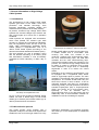
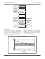
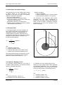
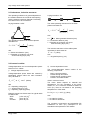
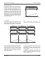
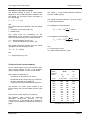
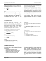
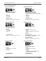
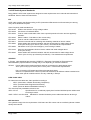
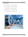
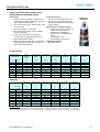
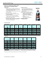
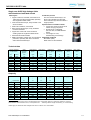
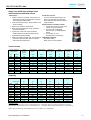
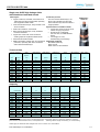
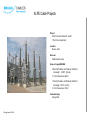
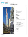
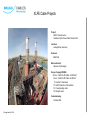
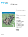
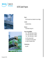
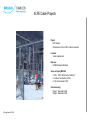
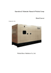
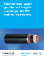
Technical user guide of highvoltage XLPE cable systems. Australia Pty Ltd www.cablegrid.com.au High Voltage XLPE Cable Systems Techincal User Guide Content 1. General information on High Voltage XLPE Cable Systems ______________ 3 1.1. Introduction _______________________________________________ 3 1.2. Cable selection process _____________________________________ 3 1.3. Service life ________________________________________________ 4 2. Cable layout and system design ___________________________________ 6 2.1. Electrical field _____________________________________________ 6 2.2. Capacity, charging current ___________________________________ 6 2.3. Inductance, Inductive reactance _______________________________ 7 2.4. Losses in cables ___________________________________________ 7 2.5. Earthing methods, induced voltage _____________________________ 8 2.6. Short-circuit current capacity __________________________________ 10 2.7. Dynamic forces ____________________________________________ 11 2.8. Metallic sheath types ________________________________________ 11 3. XLPE Cable System Standards ____________________________________ 13 4. Technical data sheets ___________________________________________ 14 500 / 290 kV XLPE Cable 400 / 230 kV XLPE Cable 345 / 200 kV XLPE Cable 220 / 127 kV XLPE Cable 132 / 76 kV XLPE Cable 5. XLPE Cable Reference Projects from Brugg __________________________ 20 Brugg Cables Page 2 High Voltage XLPE Cable Systems Techincal User Guide 1. General information on High Voltage Cable Systems 1.1 Introduction The development of high voltage XLPE Cable Systems goes back to the 1960’s. Since then production and material technology have improved significantly, providing reliable and maintenance-free products to the utility industry. At present, numerous high voltage XLPE cable systems with nominal voltages up to 500 kV and with circuit lengths up to 40 km are in operation worldwide. Cable systems are equipped with accessories, which have passed the relevant type tests pursuant to national and international standards, such as long-duration tests. As one of the first XLPE cable manufacturers worldwide Brugg Cables passed a Prequalification Test on a 400 kV XLPE Cable System according to the relevant international standard IEC 62067 (2001). This test required one year of operation, along with the thermal monitoring of all cables, joints and terminations installed. It was successfully completed at CESI Laboratory in Milan, Italy in 2004. Test Setup of Prequalification Test As one of just a few providers worldwide, Brugg Cables can offer a broad range of both XLPE cables (up to 500 kV) and oil-filled cables (up to 400 kV) as well as their accessories. Typical sample of a 2500mm2 500 kV XLPE cable Modern XLPE cables consist of a solid cable core, a metallic sheath and a non-metallic outer covering. The cable core consists of the conductor, wrapped with semiconducting tapes, the inner semiconducting layer, the solid main insulation and the outer semiconducting layer. These three insulation layers are extruded in one process. The conductor of high voltage cables can be made of copper or aluminium and is either round stranded of single wires or additionally segmented in order to to reduce the current losses. Depending on the customer’s specifications it can be equipped with a longitudinal water barrier made of hygroscopic tapes or powder. The main insulation is cross-linked under high pressure and temperature. The metallic sheath shall carry the short-circuit current in case of failure. It can be optionally equipped with fibers for temperature monitoring. Finally, the outer protection consists of extruded Polyethylene (PE) or Polyvinylchloride (PVC) and serves as an anti-corrosion layer. Optionally it can be extruded with a semiconducting layer for an after-laying test and additionally with a flame-retardant material for installation in tunnels or buildings if required. 1.2 Cable selection process This broad product range together with a systematic analysis of the technical requirements enables the user to find the right solution for every Brugg Cables application. Additionally, our consulting engineers can assist you in the development of customized solutions. Page 3 High Voltage XLPE Cable Systems Techincal User Guide Customer requirements Load, Voltage level, Short-circuit current, Laying condition Type of Insulation Cable type and design Economic aspects (Price, Losses) Conductor Material (Cu, Al) Route length and layout Earthing method of sheath Economic aspects, Safety margin Conductor cross-section Short-circuit and thermal rating Indoor or Outdoor Selection of cable accessories Leakage path requirements Losses, Economic aspects Determination of Laying condition Local boundaries, Safety regulation Selection process of cable design 1.3 Service life Cables are among the investment goods with a high service life of over 40 years. The service life of a cable is defined as its operating time. It is influenced by the applied materials, the constructive design, the production methods and the operating parameters. Regarding the material technology Brugg Cables has many years of experience and investigation together with extensive experience in the field of cable systems gained over the years. Lifetime curve of XLPE cables Breakdown stress (kV/mm) 50 45 40 35 30 25 20 15 10 5 0 1,0E+00 1,0E+01 1,0E+02 1,0E+03 1,0E+04 Cable lifetime (hours) Lifetime curve of XLPE cables Brugg Cables Page 4 High Voltage XLPE Cable Systems The following rules apply for all organic insulation materials in general: - An increase of the operating temperature by 8 to 10°C reduces the service life by half. - An increase of the operating voltage by 8 to 10% reduces the service life by half. The influence of the voltage on the service life is expressed in the following service life law (see graph above): t En = const Techincal User Guide Other operating parameters of decisive importance are: - Voltage level and transient voltages such as switch operations, lightning impulses - Short-circuit current and related conductor temperatures - Mechanical stress - Ambient conditions like humidity, ground temperatures, chemical influences - Rodents and termites in the vicinity with E = Maximum field strength at the conductor surface of the cable n = Exponent stating the slope t = Time Brugg Cables Page 5 High Voltage XLPE Cable Systems Techincal User Guide 2. Cable layout and system design The dimensioning of a high voltage cable system is always based on the specifications and demands of the project at hand. The following details are required for calculation: - The type of cable insulation - Nominal and maximum operating voltage - Short-circuit capacity or short-circuit current with statement of the effect time - Transmission capacity or nominal current - Operating mode: permanent operation or partial load operation (load factors) - Ambient conditions: Type of installation Ambient temperatures (incl. external effects) Special thermal resistance of the ground The calculation of the admissible load currents (ampacity) and the cable temperatures is performed in accordance with the IEC publication 60287. At Brugg Cables, professional computer programs are in use for the calculation of the various cable data. 2.1 Electrical field In initial approximation, the main insulation of a high voltage XLPE cable can be regarded as a homogenous cylinder. Its field distribution or voltage gradient is therefore represented by a homogenoius radial field. The value of the voltage gradient at a point x within the insulation can therefore be calculated as: Ex Uo r rx ln a ri E (kV/mm) ri rx ra with Uo = Operating voltage (kV) rx = Radius at position x (mm) ra = External radius above the insulation (mm) ri = Radius of the internal field delimiter (mm) x The electrical field strength is highest at the inner semiconductor and lowest above the insulation (below the external semiconductor, rx = ra). Field distribution within a high voltage XLPE cable 2.2 Capacity, charging current The operating capacity depends on the type of insulation and its geometry. The following formula applies for all radial field cables: Cb 5.56 r (F/km) D ln d with r = Relative permittivity (XLPE: 2,4) D = Diameter over main insulation (mm) Brugg Cables d = Diameter over inner semiconducter (mm) Single-core high voltage XLPE cables represent an extended capacitance with a homogenous radial field distribution. Thus a capacitive charging current to earth results in the following formula: I C U 0 C b (A/km) with Uo = Operating voltage (kV) = Angular frequency (1/s) Cb = Operating capacity (µF/km) Page 6 High Voltage XLPE Cable Systems Techincal User Guide 2.3 Inductance, Inductive reactance The operating inductance in general depends on the relation between the conductor axis spacing and the external conductor diameter. Practically, two cases have to be considered: Laying formation: flat Laying formation: trefoil The mean operating inductance for the three phases calculates as a a' Lm 2 10 4 ln 0,779 rL a 2r a The operating inductance for all three phases calculates as: a L 2 10 4 ln 0,779 rL 2r a (H/km) with a = Phase axis distance (mm) rL = Diameter of conductor over inner semiconducting layer (mm) a (H/km) with a’ = 3 2 a Mean geometric distance (mm) a = Phase axis distance (mm) rL = Diameter of conductor over inner semiconducting layer (mm) The inductive reactance of the cable system calculates for both cases as: X L [/km] with = Angular frequency (1/s) 2.4 Losses in cables Voltage-dependent and current-dependent power losses occur in cables. I) Voltage-dependent losses Voltage-dependent power losses are caused by polarization effects within the main insulation. They calculate to: Pd U o2 C b tan (W/km) with Uo = Operating voltage (kV) = Angular frequency (1/s) Cb = Operating capacity (µF/km) Dielectric power loss factors tan for typical cable insulations are: XLPE (1,5 to 3,5) 10–4 EPR (10 to 30) 10–4 Oil cable (18 to 30) 10–4 II) Current-dependent losses The current-dependent losses consist of the following components: - Ohmic conductor losses - Losses through skin effect - Losses through proximity effect - Losses in the metal sheath Ohmic conductor losses The ohmic losses depend on material and temperature. For the calculation of the ohmic losses R I², the conductor resistance stated for 20°C (Ro) must be converted to the operating temperature of the cable: R = Ro [1 + ( - 20°C )] [/km] with = 0.0393 for Copper = 0.0403 for Aluminium The conductor cross-section and admissible DC resistances at 20°C (Ro) correspond to the standards series pursuant to IEC 60228. Brugg Cables Page 7 High Voltage XLPE Cable Systems Techincal User Guide Losses through skin effect The losses caused by the skin effect, meaning the displacement of the current against the conductor surface, rise approximately quadratic with the frequency. This effect can be reduced with suitable conductor constructions, e.g. segmented conductors. Losses through proximity effect The proximity effect detects the additional losses caused by magnet fields of parallel conductors through eddy currents and current displacement effects in the conductor and cable sheath. In practice, their influence is of less importance, because three-conductor cables are only installed up to medium cross-sections and single-conductor cables with large cross-sections with sufficient axis space. The resistance increase through proximity effects relating to the conductor resistance is therefore mainly below 10%. Losses in the metal sheath High voltage cables are equipped with metal sheaths or screens that must be earthed adequately. Sheath losses occur through: - Circulating currents in the system - Eddy currents in the cable sheath (only applicable for tubular types) - Resulting sheath currents caused by induced sheat voltage (in unbalanced earting systems) The sheath losses, especially high circulating currents, may substantially reduce the current load capacity under certain circumstances. They can be lowered significantly through special earthing methods. 2.5 Earthing methods, induced voltage High voltage cables have a metallic sheath, along which a voltage is induced as a function of the operating current. In order to handle this induced voltage, both cable ends have to be bonded sufficiently to the earthing system. The following table gives an overview of the possible methods and their characteristics: Standing voltage at cable ends Sheath voltage limiters required Both-end bonding No No Substations, short connections, hardly applied for HV cables, rahter for MV and LV cables Single-end bonding Yes Yes Usually only for circuit lengths up to 1 km Only at crossbonding points Yes Long distance connections where joints are required Earthing method Cross-bonding Typical application Overview of earthing methods and their characteristics Both-end bonding Both ends of the cable sheath are connected to the system earth. With this method no standing voltages occur at the cable ends, which makes it the most secure regarding safety aspects. On the other hand, circulating currents may flow in the sheath as the loop between the two earthing points is closed through the ground. These circulating currents are proportional to the conductor currents and therefore reduce the cable ampacity significantly making it the most disadvantegous method regarding economic aspects. U x Induced voltage distribution at both-end bonding Brugg Cables Page 8 High Voltage XLPE Cable Systems Techincal User Guide Single-ended Bonding One end of the cable sheath is connected to the system earth, so that at the other end (“open end”) the standing voltage appears, which is induced linearily along the cable length. In order to ensure the relevant safety requirements, the “open end” of the cable sheath has to be protected with a surge arrester. In order to avoid potential lifting in case of a failure, both earth points have to be connected additionally with an earth continuity wire. The surge arrester (sheath voltage limiter) is designed to deflect switching and atmospheric surges but must not trigger in case of a short-circuit. earth continuity U x Induced voltage distribution at single-end bonding Cross-bonding This earthing method shall be applied for longer route lengths where joints are required due to the limited cable delivery length. A cross-bonding system consists of three equal sections with cyclic Section 1 sheath crossing after each section. The termination points shall be solidly bonded to earth. Section 2 Section 3 L1 L2 L3 U x Induced voltage distribution at cross-bonding Along each section, a standing voltage is induced. In ideal cross-bonding systems the three section lengths are equal, so that no residual voltage occurrs and thus no sheath current flows. The sheath losses can be kept very low with this method without impairing the safety as in the twosided sheath earthing. Brugg Cables Very long route lengths can consist of several cross-bonding systems in a row. In this case, it is recommended to maintain solid bonding of the system ends in order to prevent travelling surges in case of a fault. In addition to cross-linking the sheaths, the conductor phases can be transposed cyclicly. This solution is especially suited for very long cable engths or parallel circuits. Page 9 High Voltage XLPE Cable Systems Techincal User Guide Calculation of the induced voltage The induced voltage Ui within a cable system depends on the mutual inductance between core and sheath, the conductor current and finally on the cable length: and where LM is the mutual inductivity between core and sheath (H/km). U i X M I L (V) The mutual inductivity between core and sheath LM calculates as follows: with XM = Mutual inductance between core and sheath (/km) I = Conductor current per phase (A) L = Cable length Two cases must be considered for the determination of the maximum occurring voltage and for the dimensioning of the surge arresters: I = IN Normal operating current (A) I = Ic Three-pole Short-circuit current (A) The mutual inductance between core and sheath calculates from the following formula: X M LM (/km) For installation in trefoil formation: 2a L M 2 10 7 ln dM (H/km) For installation in flat formation: 2 3 2 a (H/km) L M 2 10 7 ln d M with a = Axial spacing (mm) dM = Mean sheath diameter (mm) with = Angular frequency (1/s) 2.6 Short-Circuit current capacity For the cable system layout, the maximum shortcircuit current capacity for both – the conductor and the metallic sheath – have to be calculated. Both values are depending on - the duration of the short-circuit current - the material of the current carrying component - the type of material of the adjacent components and their admissible temperatue The duration of a short circuit consists of the inherent delay of the circuit breaker and the relay time. Short-Circuit current capacity of conductors The following table contains the maximum admissible short-circuit currents Ik,1s for conductors acc. to IEC 60949 with a duration of 1 second for the different conductor and insulation types. Brugg Cables Insulation material Conductor material mm2 2500 2000 1600 1400 1200 1000 800 630 500 400 300 240 XLPE Cu Oil Al Cu kA kA 1s; 90..250°C 1s; 85..165°C 358 237 260 287 190 208 229 152 166 201 133 172 114 125 143 95 104 115 76 83 90 60 66 72 47 52 57 38 42 43 28 31 34 23 25 Admissible short-circuit currents Page 10 High Voltage XLPE Cable Systems Based on these reference values, the short-circuit currents for other durations can be converted with the following formula: I k,x 1 tc I k ,1s with Ikx = Short-circuit current during x seconds [kA] tc = Duration of short-circuit [s] Ik,1s = Short-circuit current during 1 second [kA] The above stated values were calculated on a non-adiabatic basis, which means that heat Techincal User Guide transfer from the current carrying componen to its adjacent components is allowed. Short-Circuit current capacity of metallic sheaths In addition to the above mentioned, the shortcircuit current capacity of metallic sheaths depends on their layout. The short-circuit current capacity is different for tubular sheats and wire screens, but generally the total short-circuit current capacity of a metallic sheath is the sum of the capacity of its components. Typical metallic sheath layouts with their constructional details are listed in a separate section. 2.7 Dynamic forces Single-core cables have to be fixed in their position at certain intervals. The calculation of dynamic forces for cable systems is important for the determination of the fixing interval and the layout of the fixing devices. It has to be distinguished between radial (e.g. clamps, spacers) and tangential (belts etc.) forces. The amplitude of a dynamic force in general is calculated applying the following formula: 2 10 7 I s2 Fs (kN/m) a with a = Phase axis distance (mm) Radial force The dynamic force that a spacer has to absorb is: Fr Fs Fs = Dynamic force [kN/m] = Layout factor (typical value for mid phase: 0.866) Tangential force The dynamic force that a fixing belt has to absorb is: Ft Fs Fs = Dynamic force [kN/m] = Layout factor (value for trefoil: 0.5) I s 2 Ic wherein ls = Impulse short-circuit current [kA] = surge factor (usually defined as 1.8) lc = Short-circuit current [kA] 2.8 Metallic sheath types The metallic sheath of high voltage XLPE single core cables has to fulfill the following electrical requirements: Conducting the earth fault current Returning the capacitive charging current Limitation of the radial electrostatic field Shielding of the electromagnetic field Brugg Cables Since high voltage XLPE cables are very sensitive to moisture ingression, the metallic sheath also serves as radial moisture barrier. There are several modes of preventing water and moisture penetrating into the cable and travelling within it along its length. Solutions for closed metallic sheathes can be based on welding, extruding or gluing. Some typical sheath layouts as available from Brugg Cables are shown in the following table. Page 11 High Voltage XLPE Cable Systems Techincal User Guide Typical metallic sheath types Brugg type XDRCU-ALT Brugg type XDRCU-ALT Aluminium laminated sheath with Copper wire screen Aluminium laminated sheath with Copper wire screen and integrated fibres for temperature sensing Features: - Low weight - Low losses - Low cost Features: - Low weight - Low losses - Low cost Typical application: Installation in tunnels, trenches or ducts Typical applications: Installation in tunnels, trenches or ducts Brugg type XDRCU-CUT Brugg type XDCUW-T Copper laminated sheath with Copper wire screen Copper corrugated sheath Features: - Low weight - Low losses - Low cost Features: - 100% impervious to moisture - flexible - resistant to deformation, pressure and corrosion - welded Typical applications: Installation in tunnels, trenches or ducts Typical applications: All installations in soil, especially in locations with shallow ground water level Special application: Installation in vertical shafts (up to 220 m) Brugg type XDPB-T Brugg type XDRCU-PBT Lead sheath Lead sheath with Copper wire screen Features: - 100% impervious to moisture - seamless - extruded Features: - 100% impervious to moisture - seamless - extruded - increased short-circuit capacity through additional copper wire screen Typical applications: All installations in soil Typical applications: All installations in soil Brugg Cables Page 12 High Voltage XLPE Cable Systems Techincal User Guide 3. XLPE Cable System Standards Brugg Cables´ XLPE cable systems are designed to meet requirements set in national and international standards. Some of these are listed below. IEC XLPE cable systems specified according to IEC (International Electrotechnical Commission) are among many other standards accepted. Some frequently used standards are: IEC 60183 Guide to the selection of high-voltage cables. IEC 60228 Conductors of insulated cables. IEC 60229 Tests on cable oversheaths which have a special protective function and are applied by extrusion. IEC 60287 Electric cables – Calculation of the current rating. IEC 60332 Tests on electric cables under fire conditions. IEC 60811 Common test methods for insulating and sheathing materials of electric cables. IEC 60840 Power cables with extruded insulation and their accessories for rated voltage above 30 kV (Um=36 kV) up to 150 kV (Um=170 kV). Test methods and requirements. IEC 60853 Calculation of the cyclic and emergency current rating of cables. IEC 61443 Short-circuit temperature limits of electric cables with rated voltages above 30 kV (Um=36 kV) IEC 62067 Power cables with extruded insulation and their accessories for rated voltage above 150 kV (Um=170 kV) up to 500 kV (Um=550 kV) - Test methods and requirements CENELEC In Europe, cable standards are issued by CENELEC. (European Committee for Electrotechnical Standardisation.) Special features in design may occur depending on national conditions. HD 632 Power cables with extruded insulation and their accessories for rated voltage above 36 kV (Um=42 kV) up to 150 kV (Um=170 kV). Part 1- General test requirements. Part 1 is based on IEC 60840 and follows that standard closely. HD 632 is completed with a number of parts and subsections for different cables intended to be used under special conditions which can vary nationally in Europe. ICEA / ANSI / AEIC For North America cables are often specified according to - AEIC (Association of Edison Illuminating Companies) - ICEA (Insulated Cable Engineers Association) - ANSI (American National Standards Institute) or The most frequently standards referred to are: AEIC CS7-93 Specifications for crosslinked polyethylene insulated shielded power cables rated 69 through 138 kV. ANSI / ICEA S-108-720-2004 Standard for extruded insulation power cables rated above 46 through 345 kV ISO Standards Our systems comply with the requirements of ISO 9001 and ISO 14001 and are certified by Bureau Veritas Quality International. Brugg Cables Page 13 High Voltage XLPE Cable Systems Techincal User Guide 4. Technical data sheets 500 / 290 kV XLPE Cable - Technical data and Ampacity 400 / 230 kV XLPE Cable - Technical data and Ampacity 345 / 200 kV XLPE Cable - Technical data and Ampacity 220 / 127 kV XLPE Cable - Technical data and Ampacity 132 / 76 kV XLPE Cable - Technical data and Ampacity Brugg Cables Page 14 500/290 kV XLPE Cable Single-core XLPE High Voltage Cable with Aluminium laminated sheath Cable layout Production process The inner semiconductive layer, the Copper conductor, stranded, cross-sections of XLPE main insulation and the outer 1000 sqmm and above segmented, optionally semiconductive layer are extruded in a with longitudinal water barrier single operation. Inner semiconductive layer, firmly bonded to the Special features of metallic sheath XLPE insulation XDRCU-ALT 500/290 kV Copper wire screen as short-circuit current carrying component Aluminium foil, overlapped, 0,25 mm thick, as radial diffusion barrier Low weight, low cost, internationally proven design Applicable standards IEC 62067 (2001) XLPE main insulation, cross-linked Outer semiconductive layer, firmly bonded to the XLPE insulation Copper wire screen with semi-conductive swelling tapes as longitudinal water barrier Aluminium lamninated sheath HDPE oversheath, halogen-free, as mechanical protection, optionally: with semi-conductive and/or flame-retardant layer Technical data Copper conductor cross-section Outer diameter approx. Cable weight appox. Capacitance Impedance (90°C, 50 Hz) ••• Surge impedance Min. bending radius Max. pulling force 2 kcmil mm kg/m µF/km Ω/km Ω mm kN 630 800 1000 1200 1400 1600 2000 2500 1250 1600 2000 2400 2750 3200 4000 5000 122 123 127 128 129 135 143 144 18 20 23 24 26 29 34 40 0.12 0.14 0.16 0.17 0.19 0.19 0.19 0.23 0.22 0.20 0.19 0.19 0.18 0.18 0.17 0.17 54 49 47 44 42 42 40 37 2450 2500 2550 2600 2600 2700 2900 2900 38 48 60 72 84 96 120 150 Buried in soil Buried in soil • •• Buried in soil ••• Buried in soil ••• In free air • •• In free air ••• 0.7 1.0 0.7 1.0 - - mm Ampacity • •• Load Factor 2 kcmil A A A A A A 630 800 1000 1200 1400 1600 2000 2500 1250 1600 2000 2400 2750 3200 4000 5000 954 1076 1268 1369 1473 1561 1711 1873 806 901 1055 1134 1215 1286 1403 1522 1026 1170 1377 1497 1622 1718 1901 2120 882 998 1166 1261 1361 1440 1585 1751 1053 1211 1452 1588 1728 1835 2045 2301 1152 1341 1608 1772 1944 2068 2326 2670 mm Calculation basis: Conductor temperature 90°C, 50 Hz, soil temperature 25°C, laying depth 1200 mm, soil thermal resistivity 1.0 Km/W, phase distance at flat formation 30 cm, air temperature 35° - Earthing method: Single-end bonding or Cross-bonding © 05.2006 Subject to modifications 1/1 400/230 kV XLPE Cable Single-core XLPE High Voltage Cable with Aluminium laminated sheath Cable layout Production process The inner semiconductive layer, the Copper conductor, stranded, cross-sections of XLPE main insulation and the outer 1000 sqmm and above segmented, optionally semiconductive layer are extruded in a with longitudinal water barrier single operation. Inner semiconductive layer, firmly bonded to the Special features of metallic sheath XLPE insulation XDRCU-ALT 400/230 kV Copper wire screen as short-circuit current carrying component Aluminium foil, overlapped, 0,25 mm thick, as radial diffusion barrier Low weight, low cost, internationally proven design Applicable standards IEC 62067 (2001) XLPE main insulation, cross-linked Outer semiconductive layer, firmly bonded to the XLPE insulation Copper wire screen with semi-conductive swelling tapes as longitudinal water barrier Aluminium lamninated sheath HDPE oversheath, halogen-free, as mechanical protection, optionally: with semi-conductive and/or flame-retardant layer Technical data Copper conductor cross-section Outer diameter approx. Cable weight appox. Capacitance Impedance (90°C, 50 Hz) ••• Surge impedance Min. bending radius Max. pulling force 2 kcmil mm kg/m µF/km Ω/km Ω mm kN 500 630 800 1000 1200 1400 1600 2000 2500 1000 1250 1600 2000 2400 2750 3200 4000 5000 113 114 115 118 122 123 128 135 136 16 17 18 21 24 25 28 33 38 0.12 0.13 0.15 0.17 0.19 0.20 0.20 0.21 0.26 0.23 0.22 0.20 0.19 0.19 0.18 0.18 0.17 0.17 56 53 48 45 43 41 40 39 35 2300 2300 2300 2400 2450 2450 2600 2700 2700 30 38 48 60 72 84 96 120 150 Buried in soil Buried in soil • •• Buried in soil ••• Buried in soil ••• In free air • •• In free air ••• 0.7 1.0 0.7 1.0 - - mm Ampacity • •• Load Factor 2 kcmil A A A A A A 500 630 800 1000 1200 1400 1600 2000 2500 1000 1250 1600 2000 2400 2750 3200 4000 5000 853 972 1098 1298 1402 1509 1600 1760 1931 723 819 917 1076 1158 1241 1315 1440 1565 912 1049 1199 1416 1534 1665 1767 1956 2190 788 900 1020 1195 1290 1394 1477 1628 1804 924 1068 1228 1478 1612 1755 1869 2078 2347 1006 1173 1367 1647 1804 1980 2112 2376 2739 mm Calculation basis: Conductor temperature 90°C, 50 Hz, soil temperature 25°C, laying depth 1200 mm, soil thermal resistivity 1.0 Km/W, phase distance at flat formation 30 cm, air temperature 35° - Earthing method: Single-end bonding or Cross-bonding Values apply for cables with rated voltages from 380 kV to 400 kV acc. to IEC 62067 © 05.2006 Subject to modifications 1/1 345/200 kV XLPE Cable Single-core XLPE High Voltage Cable with Aluminium laminated sheath Cable layout Production process The inner semiconductive layer, the Copper conductor, stranded, cross-sections of XLPE main insulation and the outer 1000 sqmm and above segmented, optionally semiconductive layer are extruded in a with longitudinal water barrier single operation. Inner semiconductive layer, firmly bonded to the Special features of metallic sheath XLPE insulation XDRCU-ALT 345/200 kV Copper wire screen as short-circuit current carrying component Aluminium foil, overlapped, 0,25 mm thick, as radial diffusion barrier Low weight, low cost, internationally proven design Applicable standards IEC 62067 (2001) ANSI / ICEA S-108-720-2004 XLPE main insulation, cross-linked Outer semiconductive layer, firmly bonded to the XLPE insulation Copper wire screen with semi-conductive swelling tapes as longitudinal water barrier Aluminium lamninated sheath HDPE oversheath, halogen-free, as mechanical protection, optionally: with semi-conductive and/or flame-retardant layer Technical data Copper conductor cross-section Outer diameter approx. Cable weight appox. Capacitance Impedance (90°C, 50 Hz) ••• Surge impedance Min. bending radius Max. pulling force 2 kcmil mm kg/m µF/km Ω/km Ω mm kN 500 630 800 1000 1200 1400 1600 2000 2500 1000 1250 1600 2000 2400 2750 3200 4000 5000 113 114 115 118 122 123 128 135 136 16 17 18 21 24 25 28 33 38 0.12 0.13 0.15 0.17 0.19 0.20 0.20 0.21 0.26 0.23 0.22 0.20 0.19 0.19 0.18 0.18 0.17 0.17 56 53 48 45 43 41 40 39 35 2300 2300 2300 2400 2450 2450 2600 2700 2700 30 38 48 60 72 84 96 120 150 Buried in soil Buried in soil • •• Buried in soil ••• Buried in soil ••• In free air • •• In free air ••• 0.7 1.0 0.7 1.0 - - mm Ampacity • •• Load Factor 2 mm kcmil A A A A A A 500 630 800 1000 1200 1400 1600 2000 2500 1000 1250 1600 2000 2400 2750 3200 4000 5000 859 980 1108 1311 1416 1526 1617 1780 1956 728 825 925 1087 1170 1255 1329 1456 1586 918 1056 1208 1427 1547 1680 1783 1975 2214 793 906 1027 1205 1301 1407 1491 1643 1825 927 1072 1233 1485 1619 1763 1877 2088 2359 1009 1176 1371 1652 1810 1987 2120 2384 2750 Calculation basis: Conductor temperature 90°C, 50 Hz, soil temperature 25°C, laying depth 1200 mm, soil thermal resistivity 1.0 Km/W, phase distance at flat formation 30 cm, air temperature 35° - Earthing method: Single-end bonding or Cross-bonding Values apply for cables with rated voltages from 330 kV to 345 kV acc. to IEC 62067 © 05.2006 Subject to modifications 1/1 220/127 kV XLPE Cable Single-core XLPE High Voltage Cable with Aluminium laminated sheath Cable layout Production process The inner semiconductive layer, the Copper conductor, stranded, cross-sections of XLPE main insulation and the outer 1000 sqmm and above segmented, optionally semiconductive layer are extruded in a with longitudinal water barrier single operation. Inner semiconductive layer, firmly bonded to the Special features of metallic sheath XLPE insulation XDRCU-ALT 220/127 kV Copper wire screen as short-circuit current carrying component Aluminium foil, overlapped, 0,25 mm thick, as radial diffusion barrier Low weight, low cost, internationally proven design Applicable standards IEC 62067 (2001) ANSI / ICEA S-108-720-2004 XLPE main insulation, cross-linked Outer semiconductive layer, firmly bonded to the XLPE insulation Copper wire screen with semi-conductive swelling tapes as longitudinal water barrier Aluminium lamninated sheath HDPE oversheath, halogen-free, as mechanical protection, optionally: with semi-conductive and/or flame-retardant layer Technical data Copper conductor cross-section Outer diameter approx. Cable weight appox. Capacitance Impedance (90°C, 50 Hz) ••• Surge impedance Min. bending radius Max. pulling force 2 kcmil mm kg/m µF/km Ω/km Ω mm kN 300 500 630 800 1000 1200 1400 1600 2000 2500 600 1000 1250 1600 2000 2400 2750 3200 4000 5000 99 99 100 105 111 112 115 116 119 129 12 13 15 17 20 22 24 26 30 37 0.11 0.13 0.15 0.18 0.19 0.22 0.22 0.25 0.27 0.28 0.25 0.23 0.22 0.20 0.19 0.19 0.18 0.18 0.17 0.17 59 54 51 46 44 41 40 38 36 34 2000 2000 2000 2100 2250 2250 2300 2350 2400 2600 18 30 38 48 60 72 84 96 120 150 Buried in soil Buried in soil • •• Buried in soil ••• Buried in soil ••• mm Ampacity • •• Load Factor In free air • •• In free air ••• 0.7 1.0 0.7 1.0 - - 2 kcmil A A A A A A 300 500 630 800 1000 1200 1400 1600 2000 2500 600 1000 1250 1600 2000 2400 2750 3200 4000 5000 670 877 1001 1130 1339 1450 1561 1657 1824 2002 571 739 838 939 1106 1192 1280 1353 1482 1618 714 945 1090 1241 1462 1595 1725 1847 2060 2282 621 813 930 1051 1231 1336 1440 1536 1703 1876 707 944 1092 1252 1508 1651 1791 1919 2147 2397 768 1038 1213 1405 1687 1863 2031 2195 2490 2815 mm Calculation basis: Conductor temperature 90°C, 50 Hz, soil temperature 25°C, laying depth 1200 mm, soil thermal resistivity 1.0 Km/W, phase distance at flat formation 30 cm, air temperature 35° - Earthing method: Single-end bonding or Cross-bonding Values apply for cables with rated voltages from 220 kV to 230 kV acc. to IEC 62067 © 05.2006 Subject to modifications 1/1 132/76 kV XLPE Cable Single-core XLPE High Voltage Cable with Aluminium laminated sheath Cable layout Production process The inner semiconductive layer, the Copper conductor, stranded, cross-sections of XLPE main insulation and the outer 1000 sqmm and above segmented, optionally semiconductive layer are extruded in a with longitudinal water barrier single operation. Inner semiconductive layer, firmly bonded to the Special features of metallic sheath XLPE insulation XDRCU-ALT 132/76 kV Copper wire screen as short-circuit current carrying component Aluminium foil, overlapped, 0,25 mm thick, as radial diffusion barrier Low weight, low cost, internationally proven design Applicable standards IEC 60840 (2004-04) AEIC CS7-93 ANSI / ICEA S-108-720-2004 XLPE main insulation, cross-linked Outer semiconductive layer, firmly bonded to the XLPE insulation Copper wire screen with semi-conductive swelling tapes as longitudinal water barrier Aluminium lamninated sheath HDPE oversheath, halogen-free, as mechanical protection, optionally: with semi-conductive and/or flame-retardant layer Technical data Copper conductor cross-section Outer diameter approx. Cable weight appox. Capacitance Impedance (90°C, 50 Hz) ••• Surge impedance Min. bending radius Max. pulling force 2 kcmil mm kg/m µF/km Ω/km Ω mm kN 240 300 400 500 630 800 1000 1200 1400 1600 2000 2500 500 600 800 1000 1250 1600 2000 2400 2750 3200 4000 5000 73 76 77 83 86 87 91 95 96 99 104 111 6 7 8 9 10 12 14 15 21 22 27 33 0,13 0,14 0,16 0,16 0,18 0,24 0,27 0,30 0,34 0,35 0,39 0,43 0,26 0,25 0,23 0,22 0,22 0,20 0,19 0,19 0,18 0,18 0,17 0,17 59 49 49 49 49 42 39 37 34 33 31 29 1500 1550 1600 1700 1750 1800 1850 1900 1950 2000 2100 2250 14 18 24 30 38 48 60 72 84 96 120 150 Buried in soil Buried in soil • •• Buried in soil ••• Buried in soil ••• In free air • •• In free air ••• 0.7 1.0 0.7 1.0 - - mm Ampacity • •• Load Factor 2 kcmil A A A A A A 240 300 400 500 630 800 1000 1200 1400 1600 2000 2500 500 600 800 1000 1250 1600 2000 2400 2750 3200 4000 5000 607 687 789 896 1020 1154 1377 1488 1605 1699 1869 2050 513 579 660 748 847 949 1126 1212 1302 1377 1507 1643 657 745 861 979 1123 1292 1530 1661 1810 1925 2147 2396 569 642 737 836 953 1086 1276 1380 1497 1589 1763 1954 631 721 837 960 1107 1275 1550 1691 1843 1964 2195 2456 698 799 936 1074 1249 1467 1776 1947 2147 2297 2603 2969 mm Calculation basis: Conductor temperature 90°C, 50 Hz, soil temperature 25°C, laying depth 1200 mm, soil thermal resistivity 1.0 Km/W, phase distance at flat formation 30 cm, air temperature 35° - Earthing method: Single-end bonding or Cross-bonding Values apply for cables with rated voltages from 132 kV to 138 kV acc. to IEC 60840 © 05.2006 Subject to modifications 1/1 High Voltage XLPE Cable Systems Techincal User Guide 5. XLPE Cable Reference Projects from Brugg BRUGG CABLES XLPE cable system experience above 220 kV dates back to the year 1990. Since then, more than 70 systems have been put in operation sucessfully in this voltage range all over the world. Furthermore, BRUGG CABLES is one of the leading suppliers of oil-filled cables in the Middle East. Brugg Cables Page 20 XLPE Cable Projects Project: 345kV Circuits K-Street #1 and #2 115kV Circuit Hyde Park Location: Boston, USA End-user: NStar Electric & Gas Scope of supply BRUGG: 345kV-XLPE-Kabel 1x2750kcmil (1400mm2 ) total length: 2‘910 ft (0,9 km) 12 GIS Terminations 345kV 115kV-XLPE-Kabel 1x4000kcmil (2000mm2 ) total length: 900 ft (0,3 km) 12 GIS Terminations 115kV Photo by courtesy of Mass Electric Co. Commissioning: Spring 2006 © Brugg Kabel AG 2006 XLPE Cable Projects Project: Piacenza Repowering Project 380kV Connection lines Location: Piacenza, Italy End-user: EDIPOWER (Joint Venture Edison, Italy & Atel, Switzerland) Main contractor: Consortium Piacenza 800 (Techint, Fiat Engineering, Siemens) Scope of supply BRUGG: 2.4 km 380kV-XLPE-Kabel 1x800mm2 12 GIS Terminations 380kV Commissioning: July 2005 © Brugg Kabel AG 2005 XLPE Cable Projects Project: 220kV Connection line Combined Cycle Power Plant, Block A 800 Location: Ludwigshafen, Germany End-user: BASF AG Main contractor: Siemens AG, Erlangen Scope of supply BRUGG: 20.5 km 220kV XLPE Cable 1x 2000mm2 6.5 km 220kV XLPE Cable 1x 400mm2 9 Outdoor Terminations 15 GIS-/Transformer Terminations 12 Cross-Bonding Joints 33 Straight Joints Commissioning: October 2004 © Brugg Kabel AG 2005 XLPE Cable Projects Project: 400kV & 220kV Connection lines, Shuweihat IWPP Location: United Arab Emirates End-user: Abu Dhabi Water and Electricity Authority (ADWEA) Main contractor: Siemens AG, Erlangen Scope of supply BRUGG: 9.2 km 400kV-XLPE-Kabel 1x 630mm2 15 Outdoor Terminations 400kV 15 GIS Terminations 400kV 0.8 km 220kV-XLPE-Kabel 1x1600mm2 3.7 km 220kV-XLPE-Kabel 1x 630mm2 12 Outdoor Terminations 220kV 12 GIS Terminations 220kV Commissioning: Autumn 2003 © Brugg Kabel AG 2005 XLPE Cable Projects Project: 275kV Connection lines, Substation Creux de Chippis Location: Switzerland (Valais) End-user: Power Stations Gougra Ltd. Scope of supply BRUGG: 2 km 275kV XLPE Cable 1x 1200mm2 0.5 km 275kV XLPE Cable 1x 1600mm2 1 km 275kV XLPE Cable 1x 400mm2 36 GIS Terminations 300kV 10 Transformer Terminations 300kV 24 Outdoor Terminations 300kV Commissioning: May 1997 © Brugg Kabel AG 2005 XLPE Cable Projects Project: HPP Stalden Replacement of two 275kV Cable connections Location: Valais, Switzerland End-user: KWM Kraftwerke Mattmark Scope of supply BRUGG: 2.3 km 275kV XLPE Cable 1x400mm2 6 Outdoor Terminations 275kV 6 GIS Terminations 275kV Commissioning: Stage 1: November 2004 Stage 2: December 2005 © Brugg Kabel AG 2006 Well connected. Please contact us. We will be glad to show you our first class customer service. And that Brugg Cables. with Brugg Cables you will always be well Well connected. connected. Please contact us. We will be glad to show Business Unit you our first class customer service. And that Power Systems with Brugg Cables you will always be well Business Unit Telecom & Industry Systems Klosterzelgstrasse 28 connected. CH-5201 Brugg, Switzerland Klosterzelgstrasse 28 Phone +41Unit (0)56 460 33 33 Business Phone +41Unit (0)56 460 33 33 Business Power Systems CH-5201 Brugg, Switzerland Telecom & Industry Systems Including the 28 divisions Klosterzelgstrasse Including the 28 divisions Klosterzelgstrasse CH-5201 Brugg, Switzerland High-Voltage Systems Phone +41 (0)56 460 33 33 Phone +41 (0)56 460 33 33 CH-5201 Brugg, Switzerland Telecom Phone +41 (0)56 460 33 33 Phone +41 (0)56 460 33 33 Fax +41 (0)56 460 32 67 Including the divisions Fax +41 (0)56 460 35 74 Including the divisions [email protected] [email protected] High-Voltage Systems High-Voltage Accessories Phone +41 (0)56 460 33 33 Phone +41 (0)56 460 Fax +41 (0)56 460 33 32 33 67 Telecom Industry Phone +41 (0)56 460 33 33 Phone +41 Fax +41 (0)56 (0)56 460 460 33 35 33 74 Fax +41 (0)56 460 32 98 [email protected] [email protected] Fax +41 (0)56 460 35 74 [email protected] [email protected] High-Voltage Accessories Power MV/LV Products Phone Cables, +41 (0)56 460 33 33 Phone +41 (0)56 460 33 33 Fax +41 (0)56 460 32 98 Industry Security Phone +41 (0)56 460 33 33 Phone +41 Fax +41 (0)56 (0)56 460 460 33 35 33 74 Fax +41 (0)56 460 34 83 [email protected] [email protected] Fax +41 (0)56 460 35 74 [email protected] [email protected] Power Cables, MV/LV Products Compound Phone +41 (0)56 460 33 33 Phone +41 Fax +41 (0)56 (0)56 460 460 33 34 33 83 Security Fax +41 (0)56 460 35 42 [email protected] [email protected] [email protected] Phone +41 (0)56 460 33 33 Fax +41 (0)56 460 35 74 Compound Phone +41 (0)56 460 33 33 Fax +41 (0)56 460 35 42 [email protected] Brugg Kabel AG · Klosterzelgstrasse 28 · CH-5201 Brugg · Switzerland · Phone +41(0)56 460 33 33 · Fax +41(0)56 460 35 36 · E-Mail [email protected] www.brugg.com · A Company of the BRUGG Group Brugg Kabel AG · Klosterzelgstrasse 28 · CH-5201 Brugg · Switzerland · Phone +41(0)56 460 33 33 · Fax +41(0)56 460 35 36 · E-Mail [email protected] P: 0487 007 123 W: www.cablegrid.com.au www.brugg.com · A Company of the BRUGG Group Australia Pty Ltd