1
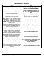
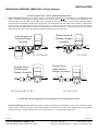
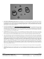
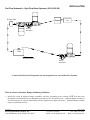
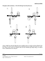
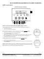
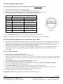
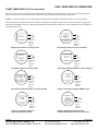
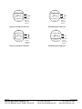
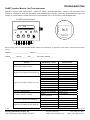
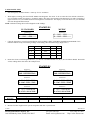
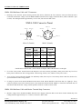
Installation / Troubleshooting Manual
FloNET (NMEA 2000) Diesel High Flow, K-Series
U.S. & Metric
This manual (part # 2000-077-01) applies to the following product part numbers:
1) N2TD-6DB-2K
2) N20D-3CB-2K
3) N2TD-6DC-2K
4) N2TD-6DD-2K
5) N2TRB6DB-2K
6) N20RB3CB-2K
7) N2TD-6CB-2K
8) N2TRB6CB-2K
9) N2TD0-6DD2K
10) N2TD0-6DD2K
11) N2TD-6ED-2K
12) N20D-3BB-2K
13) N20D0-3EE2K
14) N20D-3DC-2K
15) N20D0-3BB2K
10/10/08
FloScan Instrument Company, Inc.
3016 NE Blakeley Street, Seattle, WA 98105
2000-078-01
Tel: (206) 524-6625
Email: [email protected]
Fax: (206) 523-4961
Http://www.floscan.com
10/10/08
FloScan Instrument Company, Inc.
3016 NE Blakeley Street, Seattle, WA 98105
2000-078-01
Tel: (206) 524-6625
Email: [email protected]
Fax: (206) 523-4961
Http://www.floscan.com
!
INSTALLATION PLANNING
!
READ ME FIRST - Detailed Mechanical & Electrical Planning Saves Installation Hours!
FloScan systems are not difficult to install. Installing one requires only basic electrical & mechanical skills. With forethought and
planning, your system will be installed with few problems.
I. Installation Preparation:
Review the pre-installation booklet and mechanical installation instructions, then survey your vessel. Determine where the
Sensor(s), Pulsation Damper(s), NMEA 2000 Interface Hub, Fuel-Tron, & Fuel-Tron Screen Selection Switch are to be mounted.
Place them at their approximate locations. Measure fuel line lengths between system components, (Primary Filter, Sensor(s),
Damper(s), Engine, and Fuel Tank. Determine fitting sizes and type of fittings needed for each plumbing connection, (JIC, SAE,
NPT, NPTF, or Hose Barb).
FloScan Series K High Flow, Diesel system components have 1”, and ½” Female NPT ports.
FloScan Series K Standard Flow, Diesel, system components have ¼” Female NPT ports.
FloScan Gasoline High Flow, system components have ½” Female NPT ports.
FloScan Gasoline Standard Flow, system components have ¼” Female NPT ports.
Gasoline Fuel Systems: USCG requires Type A-1 Fuel Hose to be installed between the fuel tank and the engines’ fuel inlet
connection. Type B-1 may be used if certain safety requirements are met, (33 CFR, Subpart J, 183.558). 33 CFR Subpart J,
183.532 require hose clamps to be made from a corrosion resistant material. To meet American Boat & Yacht Council, (ABYC)
standards, the clamps must be made from a corrosion resistant metal, (ABYC, H-24.11.1).
Diesel Fuel Systems: Fuel hose and fittings can comprise a significant portion of the total installation cost. Costs for A-1 Fabric
Braid hose & hose barb fittings are approximately 1/3rd the cost of Steel Braid hose & JIC fittings. Both Type A-1 fabric braided
hose and wire braided hose meet exactly the same regulatory requirements, (USCG & ABYC) but fabric braid installation costs
are far less. For more information contact Ed Sanford, FloScan’s Technical Service Manager at extension 302.
Fabric Braid A-1 fuel hose generally uses hose barb fittings. These come in a wide range of Hose Barb to Male NPT, JIC, SAE,
& NPTF sizes and combinations. Example: 12 HB X 16 MNPT, (3/4” Hose Barb by 1” Male NPT). Steel Braid, Aeroquip type
A-1 fuel hose have reusable hose end fittings. Aeroquip type hose ends come in a wide variety of types and sizes, (JIC, SAE,
NPT, & NPTF).
Review the electrical installation instructions.
II. Mechanical Installation:
Install or mount the Sensor/Pulsation Damper assemblies, or Sensors, NMEA 2000 Interface Hub, Fuel-Tron and Switch.
III. Plumbing:
Fabric Braid A-1 Fuel Hose: Install the correct HB X MNPT fitting into each fuel system component: Tank, Manifolds, Filter,
Sensor(s), Damper(s), and Engine. Assemble fittings using a fuel proof pipe thread sealant. Never use Teflon Tape. Referring to
the Fuel Flow Schematic, run the fuel hose between system components. Cut to correct length with a pocket or razor knife. Hoses
should not be twisted, have adequate slack, an ample radius at all bends and be supported at reasonable distances, approximately
2-4 feet. When clamping hose onto the barbs, use 2 narrow or 1 wide stainless hose clamp on each hose end.
Wire Braid A-1 Aeroquip Type Fuel Hose: Install the correct fitting into each fuel system component: Tank, Manifolds, Filter,
Sensor(s), Damper(s), and Engine. Assemble fittings using a fuel proof pipe thread sealant. Never use Teflon Tape. Referring to
the Fuel Flow Schematic, run the fuel hose between system components. Cut to correct length and install hose ends.
•
•
If you choose to do this yourself, rent a hose-cutting tool and purchase a tube of assembly lubricant.
Most dealers will cut and assemble both hose ends for $10 per hose. Some charge as much as $40.
04/09/2008
FloScan Instrument Company, Inc.
3016 NE Blakeley Street, Seattle, WA 98105
2000-080-00
Tel: (206) 524-6625
Email: [email protected]
Fax: (206) 523-4961
Http://www.floscan.com
Hoses should not be twisted, have adequate slack, an ample radius at all bends and be adequately supported at reasonable
distances, approximately 2-4 feet. AP-50 copper sealing washers or Flaretite fitting seals may be required to seal JIC & SAE
fittings.
IV. Electrical Installation:
If the NMEA 2000 backbone has not been run into the engine room, open and survey your vessel’s wire ways and determine how
and where it should be run.
Measure the cable length distance from each sensor. Wire each Sensor to the NMEA 2000 Interface Hub with 18 AWG, 3conductor shielded cable. Always connect the cable shield drain to the vessels bonding system or engine block.
Wire Terminations—referring to the wiring diagram, connect the Sensor(s) to the NMEA 2000 Interface Hub and the Fuel-Tron
to its display cycling switch with crimp type butt or ring connectors. Always cover connectors and wire ends with heat shrink
tubing.
Isolated Ground Electrical Systems: FloScan manufactures 12 VDC to 12 VDC, (PN 7000-097-00) and 24 VDC to 12 VDC,
(PN 7000-096-00) Isolated Ground Power Supplies / Voltage Reducers. These power supplies electrically isolate the FloScan
system from ship’s power and are used by the Washington State Ferry System and other large steel and aluminum vessel
operators. Additionally mounting sensors onto a non-conductive surface and using short lengths of non-metallic fabric braid fuel
hose to connect them further isolates the system.
Diesel Fuel is non-conductive but does contain a, “Static Electricity Dissipater” additive to minimize the risk of fuel tank fires
and explosions. Even with this additive, the electrical resistance of Diesel Fuel is extremely high and can be considered nonconductive. Installing the FloScan system with Isolated Ground power Supplies, Non-Conductive Sensor Mounting Surfaces and
Fabric Braid Fuel Hose will electrically isolate it from the vessel’s hull.
V. Pre-Startup:
•
Always Prime the fuel system before Engine Start-Up. This prevents your engine from becoming air-bound. If you have an
electric priming or boost pump, circulate fuel for 10 minutes while checking for leaks. If the fuel system does not have an
electric priming pump, use the engine's manual pump. Before starting, slightly open or crack the lift pumps' outlet fitting. Pump
until all air is purged at the lift pumps' outlet. Before start-up, verify that all fuel system fittings are tight.
VI. Instance Selection:
Refer to the Instance Selection & Operation sheet to determine the correct Instance setting. When known, place the White
Recessed Arrow Switch at the correct setting.
VII. Operation Selection:
Refer to the Instance Selection & Operation sheet to determine the correct Operation setting. When known, place the Green
Rotary Switch at the correct setting.
VIII. System Start-Up:
Start and run your engines. Look for leaks and other installation problems. If system is not operating properly refer to the
Troubleshooting Instructions and correct any deficiencies.
IX. Calibration:
When system is running properly, refer to the calibration instructions and calibrate your system. If installed properly, initial
calibration takes less than one hour. After consuming some fuel, final calibration should only take a few minutes.
04/09/2008
FloScan Instrument Company, Inc.
3016 NE Blakeley Street, Seattle, WA 98105
2000-080-00
Tel: (206) 524-6625
Email: [email protected]
Fax: (206) 523-4961
Http://www.floscan.com
• The US Code of Federal Regulations, (CFR’s) contain no requirement for using Type A-1, A-2, B-1 or B-2, USCG
approved fuel hose on diesel powered pleasure vessels. To meet ABYC standards, fuel hose shall comply with the
requirements of UL 1114 Marine (USCG Type A) Flexible Fuel-Line Hoses, or SAE J1527 Marine (ABYC H-33.6.1) FuelLine Hoses.
USCG approved fuel hose with either fabric or wire reinforcing braid meet the following standards:
Hose Marking
USCG Type A-1
USCG Type A-2
USCG Type B-1
USCG Type B-2
Permeation Rating
100g/m²/24hrs.
300g/m²/24hrs.
100g/m²/24hrs.
300g/m²/24hrs.
2½ Minute Fire Test
Required
Required
Not Required
Not Required
Table I
Cost comparison between steel & fabric braid A-1 fuel hose on a 50’ Diesel pleasure vessel with “Stand-up” engine room:
48’, ¾” Hose / Engine x 2 = 96’
Hose End Fittings, 28 Ends
Hose End Assembly Fee
Stainless Hose Clamps
Fittings 16 x 12
Fittings 12 x 12
Fittings 8 x 12
Aeroquip A-1 Steel Braid Hose
with
JIC x MNPT Fittings
$9.73/Ft x 96’= $934.08
$11.50 per End, x 28 = $322
$10/Hose x 14 = $140
N/A
4ea x $13.80 = $55.20
20ea x $11.90 = $238
4ea x $10.75 = $43
A-1 Fabric Braid Hose
with
HB x MNPT Fittings
$5.00/Ft x 96’= $480
N/A
N/A
28ea x $1.49 = 41.72
4ea x $5.39 = $21.56
20ea x $4.20 = $84
4ea x $3.59 = $14.36
Totals:
$1732.28
$641.64
Table II
04/09/2008
FloScan Instrument Company, Inc.
3016 NE Blakeley Street, Seattle, WA 98105
2000-080-00
Tel: (206) 524-6625
Email: [email protected]
Fax: (206) 523-4961
Http://www.floscan.com
Installation Do’s & Don’ts
Do
Don’t
Always use a Fuel Proof Pipe Thread Sealant when
assembling fittings into fuel system components,
(Locktite PST, Rector Seal, or equivalent).
Never use Teflon Tape!
Use thin wall, low pressure, full flow type
NPT or NPTF hose barb fittings.
If possible avoid using Push-Lok, Barb-Tite,
JIC or SAE swivel fittings. If used, always
install
Copper AP-50 sealing washers or Flaretite
fitting seals onto JIC and SAE swivel fittings.
Double clamp all hose barb fittings.
Minimize the use of 90º elbow fittings.
Install Sensors as far from the engine as practical.
Fuel must travel “Up-hill” at least 1 or 2 inches
after leaving the Diesel Return Sensor, and all
Gasoline Sensors. Verify correct orientation and
fuel flow direction.
Avoid bolting or mounting
sensor(s) directly onto the engine.
Always install Diesel Forward Sensor/Pulsation
Damper assemblies and Gasoline Sensors in the
Fuel Pump’s Inlet or Vacuum line.
Limit Sensor/Pulsation Damper assembly
Operating Pressure to 20 PSI or Less.
Try to use A-1 Fabric Braid Fuel Hose.
If possible avoid using steel braid,
“Aeroquip” type hose, hard pipe or metal tube.
Always use 30-micron primary filters on Diesel
systems. 20- and 10-micron filters are also
acceptable if required by the engine manufacturer.
Avoid 2 or 5-micron primary filters.
Wire with Shielded Cable on Diesel installations.
If possible use a dedicated shielded wire pair for
Magnetic Pickup Tachometer Senders.
Never use unshielded wires on
Magnetic Pickup Tachometer Senders.
Connect all Negative wires to a Battery Minus (-)
Buss or directly to the Battery’s Negative Terminal.
Connect, or “Ground”, wire shields / shield drains
to the engine block or vessel bonding system.
Never connect Negative, (Battery Minus) wires
to the Vessel’s Hull, Engine Block,
or other machinery.
Always use non-illuminated switches for Totalizer
Reset, Port/Starboard Select, Hours/Synch, and
GPH/MPG.
Never use illuminated, or back-lit switches.
04/09/2008
FloScan Instrument Company, Inc.
3016 NE Blakeley Street, Seattle, WA 98105
2000-080-00
Tel: (206) 524-6625
Email: [email protected]
Fax: (206) 523-4961
Http://www.floscan.com
INSTALLATION
MECHANICAL OVERVIEW, (NMEA 2000, K Series Systems)
•
To Ensure System Accuracy, Follow All Installation Instructions.
Sensor Placement. Determine where the Flow Sensor, or Flow Sensor-Pulsation Damper assembly is to be installed. Install the
sensor, or sensor-pulsation damper assembly so that the two fuel flow arrows, (Î Î) or the, (IN and OUT) markings are on a
horizontal plane. All orientation arrows, (Ï) must be pointing up. The forward sensor or forward sensor-pulsation damper
assembly must be installed downstream of the primary filter. Do not install the sensor or either sensor assembly at a high point in
the fuel system. This could negatively impact system accuracy by trapping air. The fuel return line between the return sensors’
outlet port and fuel tank should be at least 12” long and have a 1 to 2” upward rise. This keeps the return sensor flooded,
improving accuracy. Place sensor assemblies in a protected location away from water spray.
Forward Sensor &
Pulsation Damper
Assembly
Return Sensor &
Pulsation Damper
Assembly
FloScan
Inlet
FloScan
Inlet
Outlet
Outlet
FloScan
233/ 236-1K & 2K
Return Sensor
And Pulsation
Damper Assembly
Forward Sensor
And Pulsation
Damper Assembly FloScan
Outlet
Inlet
201/ 231-1K & 2K, 235-2K
233/ 236-2K
FloScan
Outlet
Inlet
201/ 231/ 235-2K
*Caution: Diesel System Components are not designed for use on Gasoline Fuel Systems.
•
Determine fitting type & size. Minimize the number of elbows and fittings. If swivel fittings are used, (JIC or SAE) their mating
surfaces must be sealed with Copper Conical Sealing Washer, (Connie Seals) or fitting seals. Fitting seals may be purchased
through Fittings Inc. in Seattle, WA (206) 767-4670, 1-800-552-0632, or a local hydraulic supply house.
04/09/2008
FloScan Instrument Company, Inc.
3016 NE Blakeley Street, Seattle, WA 98105
2000-081-00
Tel: (206) 524-6625
Email: [email protected]
Fax: (206) 523-4961
Http://www.floscan.com
•
Select Fuel-Tron Mounting Location, (If Used). The instruments’ face is waterproof and a gasket is provided to seal its bezel to
the control panel. Choose a shaded location since direct sunlight may cause the LCD display to temporarily turn dark. This does
not damage the LCD, but makes it impossible to read until cooling down. Make a cutout in the instrument panel for the FuelTron. Instrument. It has a 2” diameter and its maximum depth is approximately 1-7/8” minus the thickness of the console panel.
Mounting bracket studs extend down another ½”.
•
Pre-Startup & Installation Check. Always Prime the FloScan Fuel Monitoring System. This is an important step in preventing
your engine from becoming air bound. If you have an electric priming or boost pump, circulate fuel for 10 minutes while
checking for leaks. If the fuel system does not have an electric priming pump, use the engines manual pump. Before starting, open
or crack the lift pumps’ outlet fitting slightly. Continue pumping all air is purged and fuel flow from the lift pumps outlet. Before
start-up verify that all fuel system fittings are tight.
•
System Start-Up. Start and run your engines. Survey the installation for leaks and other problems. If the system is not operating
properly refer to the Troubleshooting Instructions and correct any deficiencies. When the engine reaches operating temperature
increase engine speed to about 1500-2000 RPM. Letting it run for five or ten minute’s helps purge residual air from the system.
•
Any vacuum leaks between the fuel tank and lift pump will allow air to be drawn into the system. These leaks cause high and/or
fluctuating GPH readings. Only severe leaks affect engine performance, but all leaks affect sensor performance and instrument
readings. Vacuum or suction leaks occur at improperly sealed primary filters, loose packing nuts on cross over & shut off valves
and improperly sealed fittings. Vacuum leaks can also occur from corroded copper fuel lines and chaffed fuel hose, (where it rubs
against bulkheads or engine parts). To verify that a suction leak is present, temporarily insert a clear piece of fuel resistant tubing
downstream of the Forward Sensors’ outlet. Observe the clear hose for at least two minutes looking for bubbles. Bubbles can
appear as a constant stream of small bubbles, or as an occasional larger bubble. Tighten all possible leak sources, grease primary
filter seals and install fitting seals on JIC/SAE fittings. Continue to observe the clear tubing until it runs clear without any
bubbles. Flex or wiggle rubber hose sections while observing the clear tubing. If bubble volume increases inspect the hose and
check its fittings. Repair as necessary.
•
When idling in neutral, (No Load) GPH fluctuations can also be caused by the governor trying to maintain a steady engine RPM.
•
Calibration. When the system is running properly, refer to the calibration instructions and calibrate your system. If installed
properly, initial calibration takes much less than 1 hour. After consuming some fuel, final calibration should only take a few
minutes.
04/09/2008
FloScan Instrument Company, Inc.
3016 NE Blakeley Street, Seattle, WA 98105
2000-081-00
Tel: (206) 524-6625
Email: [email protected]
Fax: (206) 523-4961
Http://www.floscan.com
INSTALLATION
Fuel Flow Schematic – High Flow Diesel Systems, (233 & 236-2K)
FloScan
Primary Filter
Engine
FloScan
Return Fuel
Cooler
Forward
Flow Sensor
FloScan
Tank
Fuel Flow Direction
Return
Flow Sensor
*Caution: Diesel System Components are not designed for use on Gasoline Fuel Systems.
FloScan Sensor & Pulsation Damper Plumbing Guidelines:
1. Install flow sensor & pulsation damper assemblies with their orientation arrows pointing UP Ï. Fuel must enter
through the port marked IN and exit through the port marked OUT. Install the sensor – pulsation damper assembly as
far from the engine as practical. Maximizing fuel line length between engine and sensor – pulsation damper assembly
improves instrument accuracy.
03/05/2008
FloScan Instrument Company, Inc.
3016 NE Blakeley Street, Seattle, WA 98105
4001-291-04D
Tel: (206) 524-6625
Email: [email protected]
Fax: (206) 523-4961
Http://www.floscan.com
2. Maintaining high flow velocities through the fuel lines minimizes sensor oscillations. Use the smallest approved fuel
line diameter for your engine, especially on the return line. Consult the engine owners’ manual for more information.
To insure that the return sensor remains flooded, install the return sensor – pulsation damper assembly at a low point
in the system. Fuel should travel “Up-Hill” upon exiting the return sensor.
(Continued on next page)
3. Flow sensors must always be installed downstream of a filter or debris screen (no finer than 30 micron). Particles
larger than 1200 microns may jam the sensors’ rotor and cause it to fail.
4. Flow sensor model numbers are molded into the colored plastic wire cap. Sensors are labeled FORWARD and
RETURN and must be installed in these positions for proper operation. A single stand-alone letter stamped into the
sensors’ body identifies its match code.
5. Model *236 sensors are temperature compensated and marked with their Instruments serial number, xxxxF (Forward),
xxxxR (Return). *236 Temp-comp sensor kits are precisely calibrated and matched to each instrument. The
instrument head serial number must match the flow sensor(s) serial number.
6. If there’s a shut-off valve in the return line, do not operate the engine with it closed. Fuel system pressure could
exceed the systems working pressure of 40 PSI, and may cause a catastrophic system failure. You should either tag
the valve so the engine will not run when it is closed for maintenance, or bypass it with a relief valve.
NOTE: Minimize the number of 90º elbows and pipe fittings. Excessive use may create a high vacuum, fuel
restricting, pressure drop across the forward part of the fuel system. Refer to the engine owners’ manual for
maximum, fuel pump inlet vacuum. A vacuum gauge can be used to confirm that the system is within limits.
CAUTION, DO NOT OVER TIGHTEN FITTINGS. Over-tightening may crack the sensor’s body or pulsation damper’s
base. Cracks cause leaks, and fuel leaks sometimes cause catastrophic explosions and fire. Assemble fittings with a Lubricating,
Fuel Proof, Non or Semi Hardening pipe thread sealant designed for aluminum and stainless steel threads, (Loctite 567 or equivalent).
DO NOT USE TEFLON TAPE.
TEMPERATURE COMPENSATED
Forward Sensor
Return Sensor
Kit
*236F
*236E
*236D
*236C
*236C
*236B
*236E
*236D
*236D
*236C
*236B
*236B
*6FE-2K
*6ED-2K
*6DD-2K
*6CC-2K
*6CB-2K
*6BB-2K
NON-TEMPERATURE COMPENSATED
Forward Sensor
Return Sensor
Kit
233F
233E
233D
233C
233C
233B
03/05/2008
FloScan Instrument Company, Inc.
3016 NE Blakeley Street, Seattle, WA 98105
233E
233D
233D
233C
233B
233B
3FE-2K
3ED-2K
3DD-2K
3CC-2K
3CB-2K
3BB-2K
4001-291-04D
Tel: (206) 524-6625
Email: [email protected]
Fax: (206) 523-4961
Http://www.floscan.com
INSTALLATION
Fitting/Hose End Installation – 233 & 236-2K High Flow Diesel Sensors
1.
2.
FloScan
FloScan
FloScan
Forward
Flow Sensor
3.
FloScan
Forward
Flow Sensor
4.
FloScan
Return
Flow Sensor
FloScan
Return
Flow Sensor
Always assemble hose ends and fittings into sensor assemblies using two wrenches, (at places indicated in the
drawings). One wrench is used to turn the hose end or fitting into the sensor assembly. The second acts as a backup or counter torque wrench and is applied to either the steel SAE/Female pipe adapter fitting, or the Return
Sensor’s aluminum block at its outlet port.
10/07/08
FloScan Instrument Company, Inc.
523-4961
3016 NE Blakeley Street, Seattle, WA 98105
Http://www.floscan.com
7000-381-00a
Tel: (206) 524-6625
Email: [email protected]
Fax: (206)
10/07/08
FloScan Instrument Company, Inc.
523-4961
3016 NE Blakeley Street, Seattle, WA 98105
Http://www.floscan.com
7000-381-00a
Tel: (206) 524-6625
Email: [email protected]
Fax: (206)
BRACKET ASSEMBLY
1K & 2K Hi-Cap Forward Sensor Bracket Assembly
•
90ºangle bracket part number 4001-357-00 and mounting hardware available upon request.
(Please see reverse for Return Sensor Bracket Assembly)
5/21/2003
FloScan Instrument Company, Inc.
3016 NE Blakeley Street, Seattle, WA 98105
233-056-00B
Tel: (206) 524-6625
Email: [email protected]
Fax: (206) 523-4961
Http://www.floscan.com
BRACKET ASSEMBLY
2K Hi-Cap Return Sensor Bracket Assembly
•
90ºangle bracket part number 4001-357-00 and mounting hardware available upon request.
5/21/2003
FloScan Instrument Company, Inc.
3016 NE Blakeley Street, Seattle, WA 98105
233-056-00B
Tel: (206) 524-6625
Email: [email protected]
Fax: (206) 523-4961
Http://www.floscan.com
WIRING
FloNET (NMEA 2000) Diesel Fuel Monitoring System
Single Engine FloNET Interface Module Installation using T-Connectors
NMEA
2000
Display
Device
Drop Cable
Terminating
Resistor
Tap (T-Connector)
Terminating
Tap (T-Connector) Resistor
Backbone
Cable
Tap (T-Connector)
FloNET Interface Module
Drop Cable
Network Power
Supply Connection
16.5
293.7
GPH
GAL
0
0
TOT
S4
0
E
F 0 1
2
D
C
B
3
4
5
A
9 8 7
6
Shield
R
B
Cable Shield
04/09/2008
FloScan Instrument Company, Inc.
3016 NE Blakeley Street, Seattle, WA 98105
BLACK
RED
BLACK
WHITE
Cable Shield
RED
Connect Cable Shield
Drain Wire to
Vessel Bonding System
or
Engine Block
W
CABLE
+12VDC
-12VDC
W
WHITE
Electronic
Distribution
Panel In
Accordance
With
ABYC E-11
B
CABLE
R
Forward
Return
Flow
Sensor
Flow
Sensor
Connect Cable Shield
Drain Wire to
Vessel Bonding System
or
Engine Block
Connect Cable Shield
Drain Wire to
Vessel Bonding System
or
Engine Block
2000-082-00
Tel: (206) 524-6625
Fax: (206) 523-4961
email: [email protected] http://www.floscan.com
Twin Engine FloNET Interface Module Installation using T-Connectors
NMEA
2000
Display
Device
Drop Cable
Terminating
Resistor
Tap (T-Connector)
Terminating
Tap (T-Connector) Resistor
Tap (T-Connector)
Backbone
Cable
Tap (T-Connector)
STBD
PORT
FloNET Interface Module
FloNET Interface Module
Drop Cable
Network Power
Supply Connection
16.5
293.7
GPH
GAL
Drop Cable
TOT
S4
16.8
305.4
GPH
GAL
0
0
TOT
S4
0
0
0
E
F 0 1
2
D
C
B
3
4
5
A
9 8 7
0
E
D
C
B
A
6
F 0 1
2
3
4
5
9 8 7
6
Shield
R
B
R
RED
BLACK
RED
RED
BLACK
WHITE
Cable Shield
Forward
Return
Forward
Return
Flow
Sensor
Flow
Sensor
Flow
Sensor
Flow
Sensor
Connect Cable Shield
Drain Wire to
Vessel Bonding System
or
Engine Block
04/09/2008
FloScan Instrument Company, Inc.
3016 NE Blakeley Street, Seattle, WA 98105
Connect Cable Shield
Drain Wire to
Vessel Bonding System
or
Engine Block
W
CABLE
B
Cable Shield
WHITE
Cable Shield
BLACK
W
WHITE
Cable Shield
RED
Connect Cable Shield
Drain Wire to
Vessel Bonding System
or
Engine Block
W
BLACK
B
CABLE
R
CABLE
+12VDC
-12VDC
W
WHITE
Electronic
Distribution
Panel In
Accordance
With
ABYC E-11
B
CABLE
R
Connect Cable Shield
Drain Wire to
Vessel Bonding System
or
Engine Block
Connect Cable Shield
Drain Wire to
Vessel Bonding System
or
Engine Block
2000-082-00
Tel: (206) 524-6625
Fax: (206) 523-4961
email: [email protected] http://www.floscan.com
Single Engine FloNET Interface Module & Fuel-Tron Installation using T-Connectors
FloScan
G
P
H
16.5
Fuel-Tron
SPST
Momentary ON
Switch
NMEA 2000
Drop Cable
Terminating
Resistor
Tap (T-Connector)
Terminating
Tap (T-Connector) Resistor
Backbone
Cable
Tap (T-Connector)
FloNET Interface Module
Drop Cable
Network Power
Supply Connection
16.5
293.7
GPH
GAL
TOT
S4
0
0
0
E
F 0 1
2
D
C
B
3
4
5
A
9 8 7
6
Shield
R
B
Cable Shield
04/09/2008
FloScan Instrument Company, Inc.
3016 NE Blakeley Street, Seattle, WA 98105
BLACK
RED
BLACK
WHITE
Cable Shield
RED
Connect Cable Shield
Drain Wire to
Vessel Bonding System
or
Engine Block
W
CABLE
+12VDC
-12VDC
W
WHITE
Electronic
Distribution
Panel In
Accordance
With
ABYC E-11
B
CABLE
R
Forward
Return
Flow
Sensor
Flow
Sensor
Connect Cable Shield
Drain Wire to
Vessel Bonding System
or
Engine Block
Connect Cable Shield
Drain Wire to
Vessel Bonding System
or
Engine Block
2000-082-00
Tel: (206) 524-6625
Fax: (206) 523-4961
email: [email protected] http://www.floscan.com
Twin Engine FloNET Interface Module & Fuel-Tron Installation using T-Connectors
FloScan
16.5
16.8
G
P
H
P
S
Fuel-Tron
SPST
Momentary ON
Switch
NMEA 2000
Drop Cable
Terminating
Resistor
Tap (T-Connector)
Terminating
Tap (T-Connector) Resistor
Tap (T-Connector)
Backbone
Cable
Tap (T-Connector)
PORT
STBD
FloNET Interface Module
FloNET Interface Module
Drop Cable
Network Power
Supply Connection
16.5
293.7
GPH
GAL
Drop Cable
16.8 GPH
305.4 GAL
TOT
S4
TOT
S4
0
0
0
E
F 0 1
0
2
D
C
B
3
4
5
A
9 8 7
0
0
E
D
C
B
A
6
F 0 1
2
3
4
5
9 8 7
6
Shield
R
B
R
RED
BLACK
RED
RED
BLACK
WHITE
Cable Shield
Forward
Return
Forward
Return
Flow
Sensor
Flow
Sensor
Flow
Sensor
Flow
Sensor
Connect Cable Shield
Drain Wire to
Vessel Bonding System
or
Engine Block
04/09/2008
FloScan Instrument Company, Inc.
3016 NE Blakeley Street, Seattle, WA 98105
Connect Cable Shield
Drain Wire to
Vessel Bonding System
or
Engine Block
W
CABLE
B
Cable Shield
WHITE
Cable Shield
BLACK
W
WHITE
Cable Shield
RED
Connect Cable Shield
Drain Wire to
Vessel Bonding System
or
Engine Block
W
BLACK
B
CABLE
R
CABLE
+12VDC
-12VDC
W
WHITE
Electronic
Distribution
Panel In
Accordance
With
ABYC E-11
B
CABLE
R
Connect Cable Shield
Drain Wire to
Vessel Bonding System
or
Engine Block
Connect Cable Shield
Drain Wire to
Vessel Bonding System
or
Engine Block
2000-082-00
Tel: (206) 524-6625
Fax: (206) 523-4961
email: [email protected] http://www.floscan.com
Single Engine FloNET Interface Module Installation using Barrier Terminal Strip Connectors
NMEA
2000
Display
Device
Drop Cable
TERMINATION
RESISTOR:
120 Ohm +/- 5%
1/4-Watt
TERMINATION
RESISTOR:
120 Ohm +/- 5%
1/4-Watt
NET-H
(WHITE)
NET-L
(BLUE)
-12VDC
NMEA 2000
Backbone Cable
NET-C
(BLACK)
+12VDC
NET-S
(RED)
SHIELD
SHIELD
FloNET Interface Module
Network
Power
Supply
Connection
Drop Cable
16.5
293.7
GPH
GAL
TOT
S4
0
0
0
E
B
W
R
B
2
3
4
5
A
R
F 0 1
D
C
B
9 8 7
6
W
-12VDC
CABLE
Electronic
Distribution
Panel In
Accordance
With
ABYC E-11
Cable Shield
Connect Cable Shield
Drain Wire to
Vessel Bonding System
or
Engine Block
04/09/2008
FloScan Instrument Company, Inc.
3016 NE Blakeley Street, Seattle, WA 98105
BLACK
RED
RED
BLACK
WHITE
Cable Shield
WHITE
+12VDC
CABLE
Cable Shield
Forward
Return
Flow
Sensor
Flow
Sensor
Connect Cable Shield
Drain Wire to
Vessel Bonding System
or
Engine Block
Connect Cable Shield
Drain Wire to
Vessel Bonding System
or
Engine Block
2000-082-00
Tel: (206) 524-6625
Fax: (206) 523-4961
email: [email protected] http://www.floscan.com
Twin Engine FloNET Interface Module Installation using Barrier Terminal Strip Connectors
NMEA
2000
Display
Device
Drop Cable
TERMINATION
RESISTOR:
120 Ohm +/- 5%
1/4-Watt
NET-H
(WHITE)
NMEA 2000
Backbone Cable
NET-H
(WHITE)
TERMINATION
RESISTOR:
120 Ohm +/- 5%
1/4-Watt
NMEA 2000
Backbone Cable
NET-L
(BLUE)
NET-L
(BLUE)
NET-C
(BLACK)
-12VDC
NET-C
(BLACK)
-12VDC
NET-S
(RED)
+12VDC
NET-S
(RED)
+12VDC
SHIELD
SHIELD
SHIELD
SHIELD
STBD
PORT
FloNET Interface Module
Network
Power
Supply
Connection
FloNET Interface Module
Drop Cable
16.5 GPH
293.7 GAL
Drop Cable
TOT
S4
16.8
305.4
GPH
GAL
0
0
TOT
S4
0
0
0
E
B
W
R
B
2
3
4
5
A
R
F 0 1
D
C
B
9 8 7
0
E
D
C
B
A
6
W
R
B
W
R
B
F 0 1
2
3
4
5
9 8 7
6
W
Cable Shield
Connect Cable Shield
Drain Wire to
Vessel Bonding System
or
Engine Block
CABLE
Cable Shield
RED
RED
BLACK
WHITE
WHITE
WHITE
Cable Shield
BLACK
RED
RED
BLACK
WHITE
Cable Shield
BLACK
Cable Shield
-12VDC
CABLE
Electronic
Distribution
Panel In
Accordance
With
ABYC E-11
CABLE
CABLE
+12VDC
Forward
Return
Forward
Return
Flow
Sensor
Flow
Sensor
Flow
Sensor
Flow
Sensor
Connect Cable Shield
Drain Wire to
Vessel Bonding System
or
Engine Block
04/09/2008
FloScan Instrument Company, Inc.
3016 NE Blakeley Street, Seattle, WA 98105
Connect Cable Shield
Drain Wire to
Vessel Bonding System
or
Engine Block
Connect Cable Shield
Drain Wire to
Vessel Bonding System
or
Engine Block
Connect Cable Shield
Drain Wire to
Vessel Bonding System
or
Engine Block
2000-082-00
Tel: (206) 524-6625
Fax: (206) 523-4961
email: [email protected] http://www.floscan.com
Single Engine FloNET Interface Module & Fuel-Tron Installation using Barrier Terminal Strip Connectors
FloScan
G
P
H
16.5
Fuel-Tron
SPST
Momentary ON
Switch
NMEA 2000
Drop Cable
TERMINATION
RESISTOR:
120 Ohm +/- 5%
1/4-Watt
TERMINATION
RESISTOR:
120 Ohm +/- 5%
1/4-Watt
NET-H
(WHITE)
NET-L
(BLUE)
-12VDC
NMEA 2000
Backbone Cable
NET-C
(BLACK)
+12VDC
NET-S
(RED)
SHIELD
SHIELD
FloNET Interface Module
Network
Power
Supply
Connection
Drop Cable
16.5
293.7
GPH
GAL
TOT
S4
0
0
0
E
B
W
R
B
2
3
4
5
A
R
F 0 1
D
C
B
9 8 7
6
W
-12VDC
CABLE
Electronic
Distribution
Panel In
Accordance
With
ABYC E-11
Cable Shield
Connect Cable Shield
Drain Wire to
Vessel Bonding System
or
Engine Block
04/09/2008
FloScan Instrument Company, Inc.
3016 NE Blakeley Street, Seattle, WA 98105
BLACK
RED
RED
BLACK
WHITE
Cable Shield
WHITE
+12VDC
CABLE
Cable Shield
Forward
Return
Flow
Sensor
Flow
Sensor
Connect Cable Shield
Drain Wire to
Vessel Bonding System
or
Engine Block
Connect Cable Shield
Drain Wire to
Vessel Bonding System
or
Engine Block
2000-082-00
Tel: (206) 524-6625
Fax: (206) 523-4961
email: [email protected] http://www.floscan.com
Twin Engine FloNET Interface Module & Fuel-Tron Installation using Barrier Terminal Strip Connectors
FloScan
G
P
H
16.5
16.8
P
S
Fuel-Tron
SPST
Momentary ON
Switch
NMEA 2000
Drop Cable
TERMINATION
RESISTOR:
120 Ohm +/- 5%
1/4-Watt
NET-H
(WHITE)
NMEA 2000
Backbone Cable
NET-H
(WHITE)
NET-L
(BLUE)
TERMINATION
RESISTOR:
120 Ohm +/- 5%
1/4-Watt
NMEA 2000
Backbone Cable
NET-L
(BLUE)
NET-C
(BLACK)
-12VDC
NET-C
(BLACK)
-12VDC
NET-S
(RED)
+12VDC
NET-S
(RED)
+12VDC
SHIELD
SHIELD
SHIELD
SHIELD
PORT
STBD
FloNET Interface Module
Network
Power
Supply
Connection
FloNET Interface Module
Drop Cable
16.5 GPH
293.7 GAL
Drop Cable
TOT
S4
16.8
305.4
GPH
GAL
0
0
TOT
S4
0
0
0
E
B
W
R
B
2
3
4
5
A
R
F 0 1
D
C
B
9 8 7
0
E
D
C
B
A
6
W
R
B
W
R
B
F 0 1
2
3
4
5
9 8 7
6
W
Cable Shield
Connect Cable Shield
Drain Wire to
Vessel Bonding System
or
Engine Block
CABLE
Cable Shield
RED
RED
BLACK
WHITE
WHITE
WHITE
Cable Shield
BLACK
RED
RED
BLACK
WHITE
Cable Shield
BLACK
Cable Shield
-12VDC
CABLE
Electronic
Distribution
Panel In
Accordance
With
ABYC E-11
CABLE
CABLE
+12VDC
Forward
Return
Forward
Return
Flow
Sensor
Flow
Sensor
Flow
Sensor
Flow
Sensor
Connect Cable Shield
Drain Wire to
Vessel Bonding System
or
Engine Block
04/09/2008
FloScan Instrument Company, Inc.
3016 NE Blakeley Street, Seattle, WA 98105
Connect Cable Shield
Drain Wire to
Vessel Bonding System
or
Engine Block
Connect Cable Shield
Drain Wire to
Vessel Bonding System
or
Engine Block
Connect Cable Shield
Drain Wire to
Vessel Bonding System
or
Engine Block
2000-082-00
Tel: (206) 524-6625
Fax: (206) 523-4961
email: [email protected] http://www.floscan.com
INSTANCE SELECTION & OPERATION
FloNET
FloNET Engine Measurement Instance Selection, (White Recessed Arrow Switch Settings)
The Recessed Arrow Switch is used for setting engine instances.
Mechanical & Diesel Electric Propulsion Engines
•
•
E
For a Single Main Engine or Port Main Engine: Rotate the Recessed Arrow Switch to Position “0”.
For a Starboard Main Engine: Rotate the Recessed Arrow Switch to Position “1”.
2
3
4
5
B
For a Single Auxiliary Engine or Port Auxiliary Engine: Rotate the Recessed Arrow Switch to Position “2”.
For a Starboard Auxiliary Engine: Rotate the Recessed Arrow Switch to Position “3”.
A
US or Metric Operation Selection, (Green Switch Settings)
•
1
D
C
Generators and Auxiliary Engines
•
•
F 0
9
6
8
7
Recessed Arrow
Switch
For US (Gallons): Rotate the FloNET’s Green Switch to Position “0” to display consumption in US Gallons:
FloNET Interface Module
FloScan
16.5
293.7
BLUE
COVERED
SWITCH
E
TOT
ORANGE VIOLET
COMPUTER
INTERFACE
0
0
GREEN
•
GPH
GAL
0
BLACK
E
D
C
B
A
RED
F 0 1
2
D
C
B
A
3
4
5
9 8 7
F 0
2
3
4
5
9
6
RECESSED
ARROW
1
8
7
G
P
H
16.5
6
Fuel-Tron
NMEA 2000
GREEN Switch
Fuel-Tron
Screen
Selection
Switch
For Metric (Liters): Rotate the FloNET’s Green Switch to Position “8” to display consumption in Liters:
FloNET Interface Module
FloScan
56
LPH
47283
LIT
BLUE
COVERED
SWITCH
E
TOT
ORANGE VIOLET
COMPUTER
INTERFACE
0
0
8
GREEN
BLACK
RED
E
D
C
B
A
F 0 1
2
3
4
5
9 8 7
6
RECESSED
ARROW
D
C
B
A
F 0
1
2
3
4
5
9
8
7
L
P
H
56
6
GREEN Switch
Fuel-Tron
NMEA 2000
Fuel-Tron
Screen
Selection
Switch
NOTE: All switch adjustments are made on the FloNET.
04/09/2008
FloScan Instrument Company, Inc.
3016 NE Blakeley Street, Seattle, WA 98105
2000-083-00
Tel: (206) 524-6625
Email: [email protected]
Fax: (206) 523-4961
Http://www.floscan.com
Flow Consumption (GPH or LPH)
The FloNET display’s upper line shows the rate at which your engine is consuming fuel. Depending on the Green Switch setting, the
upper line will show consumption in Gallons per Hour, or Liters per Hour.
Total Consumption (Gallons or Liters)
The FloNET display’s lower line is the totalizer. It shows the amount of fuel, in either Gallons or Liters, that your engine has
consumed since the last time the totalizer was reset.
FloNET Interface Module
16.5 GPH
293.7 GAL
BLUE
COVERED
SWITCH
56
LPH
47283
LIT
TOT
ORANGE VIOLET
COMPUTER
INTERFACE
0
GREEN
0
BLACK
FloNET Interface Module
0
RED
E
D
C
B
A
F 0 1
6
RECESSED
ARROW
TOT
ORANGE VIOLET
COMPUTER
INTERFACE
0
2
3
4
5
9 8 7
BLUE
COVERED
SWITCH
0
8
GREEN
BLACK
RED
E
D
C
B
A
F 0 1
2
3
4
5
9 8 7
6
RECESSED
ARROW
Totalizer Reset
The totalizer is reset or zeroed by pushing the Blue Switch and holding it down for 10 to 15 seconds. When the Blue Totalizer Reset
Switch is pushed down, the GALLONS or LITERS display will flash for 10 seconds then reset to zero. Flashing indicates the
instrument is in reset mode. If the Blue Totalizer Reset Switch is turned OFF, opened or released before the totalizer reads, “0.0”, the
instrument will NOT reset. If you neglect to turn OFF, open or release the Blue Totalizer Reset Switch, “0.0” continues to flash.
Additional FloNET Switches
•
Software Reset: The Orange Switch is the FloNET’s Software Reset, or Interrupt Service Routine, switch. To reset the software,
hold the Orange Switch in for 10 to 15 seconds. After 10 seconds the Interface Hub Display’s upper line will read HELLO, and
the Totalizer will be reset to “0.0”.
•
Hardware Reset: The Covered Switch is the FloNET’s Hardware Reset, or Microcontroller Restart, switch. To reset the
hardware, insert a piece of stiff wire such as a paper clip into the hole marked “S4”. Push down on the wire to close the switch
and hold for 10 to 15 seconds. After 10 seconds the Interface Hub Display’s upper line will read HELLO, and the Totalizer will
be reset to “0.0”.
•
System Data Switch: The Violet Switch is the FloNET’s data display switch. When the Violet switch is pushed the display’s
upper line will show the system kit number, or system model number. The display’s lower line’s left side will show the system
serial number. The date of manufacture will be shown the right side.
NOTE: If the FloScan FloNET unit is operating properly but the NMEA 2000 monitoring display operates intermittently, is in error,
or has no reading check the following:
1.
2.
Verify that the NMEA 2000 display is programmed to both receive and display fuel consumption data.
Depending on the number of engines on your vessel, verify that the NMEA display can be programmed for Instance 0, 1, 2, 3
If this does not resolve the issue, review the display’s instruction manual or contact the manufacturer.
04/09/2008
FloScan Instrument Company, Inc.
3016 NE Blakeley Street, Seattle, WA 98105
2000-083-00
Tel: (206) 524-6625
Email: [email protected]
Fax: (206) 523-4961
Http://www.floscan.com
IDLE CONSUMPTION ADJUSTMENT & TOTALIZER CALIBRATION
FloNET Interface Module
FloNET Interface Module
16.5 GPH
293.7 GAL
BLUE
COVERED
SWITCH
TOT
ORANGE VIOLET
COMPUTER
INTERFACE
0
GREEN
0
BLACK
0
E
D
C
B
A
RED
F 0 1
2
3
4
5
9 8 7
6
RECESSED
ARROW
PART I: Generators & Diesel Electric Propulsion Engine Systems
Contact the engine dealer or refer to the engine manual-data sheet and determine the engines:
• No load fuel consumption.
• The 10 % or 25% load, fuel consumption.
Idle Consumption Adjustment for Forward and Return, Two Sensor Generator Systems
+2%
+4%
1
2
3
4
D
C
-8%
Start and run the engine until it is at operating temperature.
Rotate the Red and Black switches to position “0”.
With no load, verify that the engine is running at the correct RPM (usually 1200, 1500, or 1800).
Rotate the Red Switch until the FloNET GPH or LPH reading matches the manufacturer’s
No-Load fuel consumption specification.
F 0
E
-6%
•
•
•
•
0%
-2%
-4%
-10%
+6%
+8%
5
B
A
-12%
9
8
+10%
6
7
+12%
-14% -16% -18%
RED Switch
Totalizer Calibration for Forward and Return, Two Sensor Generator Systems
•
•
-2%
Put a 10% or 25% load on the generator.
Rotate the Black Switch until the GPH reading matches the manufacturer’s 10% or 25% load fuel
consumption listing.
NOTE: Generators turning at 1200, 1500, or 1800 RPM will consume much more fuel at No Load than
propulsion engines. If you are unable to obtain the engine manufacturer’s consumption data proceed to
Part’s II and IV below. You should triple the readings in Part II, Table 1.
-4%
E
D
-8% C
B
-10%
A
0%
F 0
+2%
1
-6%
-12%
+4%
2
+6%
3
4 +8%
5 +10%
9
-14%
8
-16%
7
6
-20%
-18%
BLACK Switch
04/09/2008
FloScan Instrument Company, Inc.
3016 NE Blakeley Street, Seattle, WA 98105
2000-086-00
Tel: (206) 524-6625
Email: [email protected]
Fax: (206) 523-4961
Http://www.floscan.com
PART II: Propulsion Engine Systems
Idle Consumption Adjustment for Forward and Return, Two Sensor Propulsion Engine Systems
•
•
•
•
Start and run engine(s) until it is at operating temperature.
Referring to the switch diagram, rotate the Red and Black switches to position “0”.
Increase engine speed to 1800 RPM for one minute. This purges any trapped air from the system.
Return engine speed to low idle and determine its’ consumption from Table 1 below.
Table 1
•
No Load Idle Consumption
-2%
HP
Non-Turbo
w/ Turbo
100-400
0.1-0.5 GPH, (1-2 LPH)
0.3-0.7 GPH, (2-3 LPH)
400-750
0.8 GPH, (3 LPH)
1.0 GPH, (3-4 LPH)
750-1000
1.0 GPH, (4 LPH)
1.5 GPH, (5-6 LPH)
1000-1250
2.0 GPH, (7-8 LPH)
2.5 GPH, (9-10 LPH)
1250-1500
3.0 GPH, (11-12 LPH)
3.5 GPH, (13-14 LPH)
-4%
1500-2000
3.5 GPH, (13-14 LPH)
4.0 GPH, (15-16 LPH)
2000-3000
4.5 GPH, (17 LPH)
5.0 GPH, (18-19 LPH)
E
-6%
0%
F 0
+2%
1
+4%
2
D
C
-8%
-10%
3
4
B
5
A
-12%
9
8
7
+6%
+8%
+10%
6
+12%
-14% -16% -18%
RED Switch
Rotate the Red Switch until the idle GPH or LPH reading matches engine HP from Table 1.
NOTE: At this point idle consumption is approximate. It establishes operating parameters for final calibration.
Part III: Determining Optimum Tank Configuration & Cruise RPM
•
•
•
Determine the optimum fuel tank configuration for your vessel. If possible, single engine vessels should draw and return fuel to a
single tank. On twin engine vessels, try to configure the fuel system so that each engine draws and returns fuel to its’ own
dedicated tank. If your twin engine vessel has only a single tank, equal consumption rates for both engines must be assumed.
Close any cross-connect or limber line valves between tanks during calibration.
Take your vessel for a short cruise. Using the GPH or LPH reading as a guide, determine the best cruising RPM for the way you
normally operate. Don’t be concerned that the readings are slightly off. Calibration is most accurate when done at a single
cruising RPM.
Part IV: Final Calibration
•
•
•
•
•
•
•
•
•
•
•
Return to the fuel dock and top off the fuel tank(s).
Reset the totalizer so that the Interface Hub totalizer reading is zero.
Operate the generator under load, or take the vessel for a cruise. Once underway steam at your optimal cruising RPM,
(Determined in Part III). Consume a minimum of 20 to 30 gallons, (75 to 115 liters) of fuel per engine. Higher consumption gives
better accuracy.
After consuming some fuel, return to the fuel dock and top off the fuel tank(s).
Compare the FloNET totalizer reading to the fuel pump reading.
Calculate the percentage difference between the fuel pump & FloNET totalizer readings. Refer to Examples I & II below.
Determine if the FloNET totalizer is reading High or Low.
Rotate the Black Switch until the Interface Hub totalizer reading matches the fuel pump reading.
Starting at “0”, rotating the BLACK Switch in a clockwise direction increases the totalizer readings by 2% for each click.
Rotating the switch in a counter-clockwise direction decreases totalizer readings by 2%.
Totalizer readings can be increased by 10%, or reduced by 20%.
Single Engine Vessels: Please refer to Example 1, Port system, on the following page.
04/09/2008
FloScan Instrument Company, Inc.
3016 NE Blakeley Street, Seattle, WA 98105
2000-086-00
Tel: (206) 524-6625
Email: [email protected]
Fax: (206) 523-4961
Http://www.floscan.com
Example 1: Twin engine vessel with two, dedicated fuel tanks, (For single engine vessels with a
single tank, use either the Port or Starboard system calibration procedure in Example 1).
After steaming and returning to refuel. The Port tank took 89.7 gallons, (339.5 liters). It’s totalizer
reads 94.2 gallons, (356.5 liters). The Starboard tank took 93.2 gallons, (352.8 liters) and its’
totalizer reads 87.9 gallons, (332.7 liters).
•
Using the formula, calculate the percentage difference between the totalizer reading and
actual fuel consumption.
Port System Calibration
•
•
•
-2%
-4%
E
-6%
F 0
+2%
1
+4%
2
3
4
D
C
-8%
-10%
Difference in Gallons, (Liters)
x 100
Totalizer Reading
0%
5
B
A
-12%
9
-14%
8
-16%
7
6
+6%
+8%
+10%
-20%
-18%
BLACK Switch
Find the difference between the totalizer and fuel pump readings:
[94.2 gallon, (356.5 liter) totalizer reading] – [89.7 gallon, (339.5 liter) pump reading] = 4.5 gallon, (170.3 liter) difference.
Determine percentage difference between readings:
[4.5 gallon, (17.0 liter) difference] ÷ [94.2 gallon, (356.5 liter) totalizer reading] = .047 x 100 = 4.7% Higher difference.
To calibrate, rotate the Port FloNET’s Black Switch counter-clockwise to position “E”, reducing the totalizer reading by 4%.
Starboard System Calibration
•
•
•
Find the difference between the totalizer and fuel pump readings:
[93.2 gallon, (24.4 liter) fuel pump reading] – [87.9 gallon, (332.7 liter) totalizer reading]= 5.3 gallon, (20.1 liter) difference.
Determine percentage difference between readings:
(5.3 gallon, (20.1 liter) difference) ÷ (87.9 gallon, (332.7 liter) totalizer reading) = .060 x 100 = 6% Lower difference.
To calibrate, rotate the Starboard FloNET’s Black Switch clockwise to position “3”, increasing the totalizer reading by 6%.
Example 2: Twin engine vessel with a single fuel tank.
Port System Calibration
After refueling the tank took 182.9 gallons, (692 liters). The Port Totalizer reads 94.2 gallons, (356.6 liters) and the Starboard reads
87.9 gallons, (332.7 liters). With a single tank, you must assume that each engine burned 91.5 gallons, (346.3 liters).
•
•
•
Find the difference between the totalizer and fuel pump readings:
[94.2 gallon, (356.5 liter) totalizer reading] – [91.5 gallon, (346.3 liter) assumed burn) = 2.7 gallon, (10.2 liter) difference.
Determine percentage difference between readings:
[2.7 gallon, (10.2 liter) difference) ÷ [94.2 gallon, (356.5 liter) totalizer reading) = .028 x 100 = 2.8% Higher difference.
To calibrate, rotate the Port FloNET’s Black Switch counter-clockwise to position “F”, reducing the totalizer reading by 2%.
Starboard System Calibration
•
•
•
Find the difference between the totalizer and fuel pump readings:
[91.5 gallon, (346.3 liter) assumed burn] - [87.9 gallon, (332.7 liter) totalizer reading] = 3.6 gallon, (13.6 liter) difference.
Determine percentage difference between readings:
[3.6 gallon, (13.6 liter) difference] ÷ [87.9 gallon, (332.7 liter) totalizer reading] = .041 x 100 = 4.1% Lower difference.
To calibrate, rotate the Starboard FloNET’s Black Switch clockwise to position “2”, increasing the totalizer reading by 4%.
This completes system calibration. The FloNET readings should be within 5% of actual consumption. Calibrating a second time
should bring it to within 3%, especially on twin engine, single tank vessels. Larger fuel burns increase calibration accuracy.
Drastically changing operating habits (i.e. changing from mostly cruising to mostly trolling) may affect totalizer accuracy. If this
occurs re-calibration may be necessary.
04/09/2008
FloScan Instrument Company, Inc.
3016 NE Blakeley Street, Seattle, WA 98105
2000-086-00
Tel: (206) 524-6625
Email: [email protected]
Fax: (206) 523-4961
Http://www.floscan.com
04/09/2008
FloScan Instrument Company, Inc.
3016 NE Blakeley Street, Seattle, WA 98105
2000-086-00
Tel: (206) 524-6625
Email: [email protected]
Fax: (206) 523-4961
Http://www.floscan.com
FUEL TRON DISPLAY OPERATION
FloNET (NMEA 2000) Fuel-Tron Instrument
There are a variety of screens that the Fuel-Tron Instrument will display. The different display screens are accessed by pushing the
Fuel-Tron Screen Selection Switch. Each time the selection switch is pushed, a different screen is displayed.
NOTE: U.S. Gallons / GPH or Liters / LPH readings are determined by the NMEA 2000 Interface Hub’s Green Switch setting.
The Fuel-Tron Screen Selection Switch is also used for resetting fuel consumption totals on the Fuel-Tron Instrument. Toggle to the
desired fuel consumption total screen, then push & hold the Fuel-Tron Selection Switch for 10-20 seconds until the fuel consumption
total resets back to “0.0”.
FloScan
G
P
H
FloScan
Total
498.7
16.5
Gallons
Fuel-Tron
NMEA 2000
Screen
Selection
Switch
Single Engine Gallons or Liters per Hour
Fuel-Tron
Screen
Selection
Switch
Single Engine Gallons or Liters Consumed
Fuel-Tron
Fuel-Tron
NMEA 2000
FloScan
G
P
H
16.5
16.4
FloScan
Combined GPH
P
32.9
S
Fuel-Tron
NMEA 2000
Fuel-Tron
Screen
Selection
Switch
Fuel-Tron
Screen
Selection
Switch
Fuel-Tron
NMEA 2000
Twin Engine Gallons or Liters per Hour
Twin Engine Combined Gallons or Liters per Hour
FloScan
FloScan
Combined Total
MPG
1021.8
1.34
Gallons
Fuel-Tron
NMEA 2000
Fuel-Tron
Screen
Selection
Switch
Fuel-Tron
Screen
Selection
Switch
Fuel-Tron
NMEA 2000
Twin Engine Combined Gallons or Liters Consumed
Single or Twin Engine Combined MPG or LPG
FloScan
FloScan
Total
Non-Reset
Trip Avg: MPG
1.28
70584
x100
Gallons
Fuel-Tron
NMEA 2000
Fuel-Tron
Screen
Selection
Switch
Single or Twin Engine Combined
Trip Average Miles per Gallon
Fuel-Tron
NMEA 2000
Single or Twin Engine Combined Total
(Non-Resettable) Gallons or Liters Consumed
09/08/08
FloScan Instrument Company, Inc.
3016 NE Blakeley Street, Seattle, WA 98105
Fuel-Tron
Screen
Selection
Switch
2000-084-00A
Tel: (206) 524-6625
Email: [email protected]
Fax: (206) 523-4961
Http://www.floscan.com
FloScan
FloScan
Gallons Used
Gallons Used
523.1
498.7
Port
Trip A
Fuel-Tron
NMEA 2000
Stbd
Fuel-Tron
Screen
Selection
Switch
Single or Port Engine Trip A Total
FloScan
Starboard Engine Trip A Total
162.8
Trip B
NMEA 2000
NMEA 2000
Gallons Used
157.6
Fuel-Tron
Fuel-Tron
Screen
Selection
Switch
Fuel-Tron
FloScan
Gallons Used
Port
Trip A
Stbd
Fuel-Tron
Screen
Selection
Switch
Single or Port Engine Trip B Total
Fuel-Tron
NMEA 2000
Fuel-Tron
Screen
Selection
Switch
Starboard Engine Trip B Total
09/08/08
FloScan Instrument Company, Inc.
3016 NE Blakeley Street, Seattle, WA 98105
Trip B
2000-084-00A
Tel: (206) 524-6625
Email: [email protected]
Fax: (206) 523-4961
Http://www.floscan.com
TROUBLESHOOTING
FloNET Interface Module, Fuel-Tron Instrument
BEFORE CALLING FOR ASSISTANCE, COMPLETE THESE TROUBLESHOOTING CHECKS AND RECORD YOUR
FINDINGS. TECHNICAL SUPPORT REQUIRES THIS INFORMATION BEFORE A RETURN AUTHORIZATION WILL BE
ISSUED. IT TAKES ABOUT 20 MINUTES AND IS VERY IMPORTANT IN ANALYZING SYSTEM PROBLEMS.
FloNET Interface Module
16.5
293.7
GPH
GAL
BLUE
COVERED
SWITCH
FloScan
G
P
H
TOT
ORANGE VIOLET
COMPUTER
INTERFACE
0
GREEN
0
0
BLACK
RED
E
D
C
B
A
F 0 1
2
3
4
5
9 8 7
16.5
Fuel-Tron
6
RECESSED
ARROW
NMEA 2000
Before starting, please record the FloNET Module and Fuel-Tron Instrument, (if applicable) model number, serial number and switch
settings:
MODEL # _______________________ SERIAL # _________________________
GREEN_______ BLACK_______ RED_______ RECESSED ARROW_______
FAULT
Blank FloNET Module Display
Blank Fuel-Tron Display/No Backlighting
High or Low Totalizer reading. Over 10%.
Fluctuating GPH Readings
No GPH or Totalizer Readings
No Forward or Return Sensor Readings
High Forward or Return Sensor Readings
PROBABLE CAUSE
Network Power Reversed
Defective NMEA Cable
Network Power OFF
Network Power Reversed
Defective NMEA Cable
Network Power OFF
Calibration
Incorrect flow sensor(s)
Sensors Installed backwards
Sensors Wired backwards
Incorrect switch settings
Vacuum leak
Fine Primary Filter
Dirty Primary Filter
Vacuum leak / Pulsations
Wiring
Sensor orientation
Wiring /Instrument failure
Sensor Failure
Vacuum Leak
Incorrect switch settings
Sensor orientation
SEE SECTION
Section II
Section II
Section II
Section II
Section II
Section II
Calibration sheet
Section VII
Wiring Diagram
Calibration sheet
Section V
Section VII
Section II, Wiring Diagram
Sections IV, V
Wiring Diagram
Installation sheet, Section
VII
Sections I, II, III, VII
Sections I, II, III
Section V
Calibration sheet
Section VII
10/10/08
FloScan Instrument Company, Inc.
3016 NE Blakeley Street, Seattle, WA 98105
2000-085-00A
Tel: (206) 524-6625
Email: [email protected]
Fax: (206) 523-4961
Http://www.floscan.com
I. DIAGNOSTIC TEST:
1.
Start the engine(s) and allow them to “warm-up” for 5 to 10 minutes.
With engine(s) running, place the FloNET Module into Diagnostic Test mode. To do so rotate the Green Switch to Position 1,
(for US Gallons models) or Position 9, (for Metric models). This places the instrument into Diagnostic Test mode. The display’s
upper line shows raw, (un-calibrated) fuel flow through the Forward Sensor. The display’s lower line shows raw, (un-calibrated)
fuel flow through the Return Sensor.
NOTE: Calibration settings do not affect diagnostic mode readings.
2.
EXAMPLES:
US STANDARD
METRIC
POSITION 2:
F
R
3.
497.6
518.3
POSITION A:
GPH
GPH
F
R
LPH
LPH
Using the chart below, record Forward and Return sensor readings at IDLE, 1000 RPM, 1500 RPM and 1800 RPM. Circle
S or F to indicate steady or fluctuating readings. If fluctuating, show fluctuation range, (High & Low).
Forward
4.
1883
1962
Return
S
F
IDLE
S
F
S
F
1000
S
F
S
F
1500
S
F
S
F
1800
S
F
Rotate the Green Switch through Positions 2, 3, 4 & 5 for US Gallon models or A, B, C, & D for Metric Models. Record the
various readings in the chart below the example boxes.
EXAMPLES:
POSITION 1:
POSITION 9:
287.1 NET GPH
F&R DIFFERENTIAL
1086 NET LPH
F&R DIFFERENTIAL
POSITION 3:
POSITION B:
F 75 F FUEL TMP
R 90 F FUEL TMP
Differential
Flow Rate
5.
F 24 C FUEL TEMP
R 32 C FUEL TEMP
POSITION 4:
POSITION C:
F 19373 PROGRAM
R 47932 K-FACTOR
F 19373 PROGRAM
R 47932 K-FACTOR
Temperature
Forward
Return
Display K-Factor
Forward
Return
Sensor K-Factor
Forward
Return
Measure fuel-line length between system components and draw a system sketch.
10/10/08
FloScan Instrument Company, Inc.
3016 NE Blakeley Street, Seattle, WA 98105
2000-085-00A
Tel: (206) 524-6625
Email: [email protected]
Fax: (206) 523-4961
Http://www.floscan.com
II. SUPPLY VOLTAGE VERIFICATION
NMEA 2000 Backbone Cable with T-Connectors
1.
Referring to the connector pin-out drawing and the table below, disconnect the first connector nearest the Network Power
Connection and measure voltage across the RED and Black Network Power Supply Connection Wires, (NET-S and NET-C pins
or holes). The reading should be approximately 12 to 14 VDC, but not lower than 9 VDC.
NMEA 2000 Connector Pinout
NET-C (3)
Shield (1)
NET-S (2)
NET-S (2)
NET-H (4)
NET-L (5)
Shield (1)
NET-L (5)
NET-H (4) NET-C (3)
Mini-C (Female)
Micro-C (Female)
NAME
PAIR
PIN
COLOR
Shield
Drain
1
Bare
NET-S
Power
2
Red
NET-C
Power
3
Black
NET-H
Signal
4
White
NET-L
Signal
5
Blue
NOTE: Micro-Cable Pin-Out is on the left side of diagram. Mini-Cable Pin-Out is on the right.
2.
If 12 VDC is not present, measure between the Red power wire and a known good battery minus point. There may be a loose
battery minus connection or other wiring problem. Check wiring, switches, fuse, and the 12 VDC power source.
3.
12 to 14 VDC is present between the Red wire and battery minus, there may be a loose battery minus connection, broken wire,
open termination or other wiring problem.
4.
If voltage is present across the Red & Black Network Power Feed, and the FloNET or Fuel-Tron does not, “Light-Up”. Every
connector junction between the Network Power Feed connection and the FloNET Module or Fuel-Tron Instrument must be
disconnected and checked for voltage, until the problem connector or cable section is found.
NMEA 2000 Backbone Cable with Barrier Terminal Strip Connectors
5.
Measure voltage across the RED and Black Network Power Supply Connection Wires at the Power Feed Terminal Strip. The
reading should be approximately 12 to 14 VDC, but not lower than 9 VDC.
10/10/08
FloScan Instrument Company, Inc.
3016 NE Blakeley Street, Seattle, WA 98105
2000-085-00A
Tel: (206) 524-6625
Email: [email protected]
Fax: (206) 523-4961
Http://www.floscan.com
6.
If 12 VDC is not present, measure between the Red power wire and a known good battery minus point. There may be a loose
battery minus connection or other wiring problem. Check wiring, switches, fuse, and the 12 VDC power source.
7.
If 12 to 14 VDC is present between the Red wire and battery minus, there may be a loose battery minus connection, broken wire,
open termination or other wiring problem.
If voltage is present across the Red & Black Network Power Feed, and the FloNET Module or Fuel-Tron Instrument does not
“Light-Up” supply voltage on every terminal strip must be checked for voltage until the problem connector or cable section is
found.
8.
III. SENSOR(S) TEST
1.
With engine(s) idling, measure and record voltage between the RED power and BLACK wires on the butt
___________VDC
connector side of the Forward Sensor. Voltage readings should be 12 to 14 VDC.
2.
Move the voltmeters’ negative lead to the WHITE signal wire. With engine idling, measure and record the
___________VDC
voltage. Readings between 4 and 10 VDC usually indicate a good sensor.
3.
Stop the engine while observing your voltmeter. Readings should fluctuate between a high of 9 to 12 VDC,
___________VDC
and a low of 0 to 4 VDC as the sensors’ turbine slows to a stop.
NOTE: This may not be seen on digital voltmeters.
4.
With engine(s) idling, measure and record voltage between the RED power and BLACK wires on the butt
___________VDC
connector side on the Return Sensor, (If used). Voltage should be 12 to 14 VDC.
5.
Move the voltmeters’ negative lead to the White (Signal) wire. With engine idling, measure and record the
___________VDC
voltage. Readings between 4 and 10 VDC usually indicate a good sensor.
6.
Stop the engine and observe the voltmeter. Voltage readings should fluctuate between a high of 9 to 12 VDC,
___________VDC
and a low of 0 to 4 VDC as the Sensors’ turbine slows to a stop.
NOTE: This may not be seen on digital voltmeters.
7.
The Sensor(s) may be defective if voltage readings in steps 3 & 5 remain constant.
___________VDC
IV. PULSATION PROBLEMS
A stiff anti-siphon valve(s) or miss-plumbed Pulsation Damper(s) can cause fluctuating GPH readings. These are most pronounced at
low Rpm’s and tend to disappear around mid throttle. They are annoying, and can affect totalizer accuracy. To eliminate, repair or
replace any defective valves, or re-plumb dampers according to the Fuel Flow Schematic Instructions.
V. FINDING FUEL SYSTEM VACUUM LEAKS
Fluctuating GPH and High Totalizer Readings are usually caused by a small vacuum leak between the fuel tank and fuel pump inlet.
Fluctuations tend to be between 2 and 4 GPH. These vacuum leaks also affect totalizer accuracy, causing it to read 15 to 100% high.
Larger leaks produce greater fluctuations and higher readings. They generally do not affect engine performance.
Finding suction leaks can be time-consuming. When approached properly, they can usually be found and repaired quickly. Two
common places for suction leaks to occur are at the primary fuel filter - water separator, and/or a loose valve stem packing nut.
Remove the filter housing and coat all o-rings, gaskets and sealing surfaces with a medium to heavy grease, (Do not use oil) and
reassemble. Grease all valve stem packing’s and gently tighten gland nuts. Don’t over tighten, valve handles should turn freely.
Tighten all hose clamps and compression fittings. Don’t over tighten. Run the engine for 5 to 10 minutes observing GPH readings. If
you’ve found the problem, fluctuations should be reduced to less than ½ GPH.
If the problem persists, temporarily install a clear piece of fuel resistant hose downstream of the forward flow sensor. Run the engine
and watch for a stream of small bubbles in the clear hose, or an occasional larger bubble. Sometimes shining a light through the hose
makes bubbles easier to see.
10/10/08
FloScan Instrument Company, Inc.
3016 NE Blakeley Street, Seattle, WA 98105
2000-085-00A
Tel: (206) 524-6625
Email: [email protected]
Fax: (206) 523-4961
Http://www.floscan.com
Observe the clear hose while shaking the fuel lines. If the bubble stream continually increases or decreases you’ve found the leak
area. Repair or replace as needed. If this occurs one-time, you probably dislodged some trapped air.
If the leak hasn’t been found, the last step is to inspect each pipe joint. Thread sealant should be visible around each joint. If not, that
joint is suspect and must be resealed. After resealing run the engine for a few minutes to purge any remaining air. There should now
be bubble free fuel running through the clear hose. If bubbles are still present a leak was missed. Recheck your work. After all the
leaks are stopped, remove the clear hose.
VI. FUEL FILTERS
A dirty Primary fuel filter or one that is too fine, (2 or 5 micron) tends to draw vapor bubbles out of the fuel, causing fluctuations and
high readings. Replace it with a new Engine Manufacturer Recommended Filter, usually 10 or 30-microns.
VII. FLOW SENSOR ORIENTATION
Sensor orientation is critical for proper operation. All Sensors have their inlet and outlet ports clearly marked (IN, OUT, or Î ). This
identifies fuel flow direction. The Sensor must be, “Plumbed” correctly for it to operate properly. If there is an additional single
arrow on the Sensor body it is crucial that this single arrow points up Ï.
VIII. LOW RPM OPERATION
At idle, under a No Load condition, it is common for GPH readings to fluctuate slightly. These fluctuations are caused by the engine
governor regulating fuel flow to maintain a steady engine RPM.
This concludes system testing. If problems with your system persist,
contact FloScan Technical Support with test results.
10/10/08
FloScan Instrument Company, Inc.
3016 NE Blakeley Street, Seattle, WA 98105
2000-085-00A
Tel: (206) 524-6625
Email: [email protected]
Fax: (206) 523-4961
Http://www.floscan.com
10/10/08
FloScan Instrument Company, Inc.
3016 NE Blakeley Street, Seattle, WA 98105
2000-085-00A
Tel: (206) 524-6625
Email: [email protected]
Fax: (206) 523-4961
Http://www.floscan.com