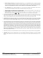
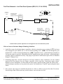
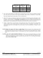
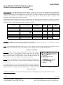
1
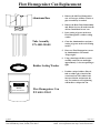
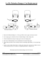
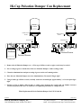
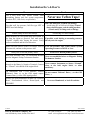
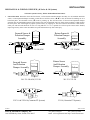
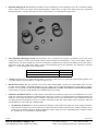
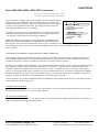
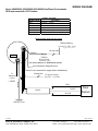
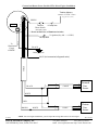
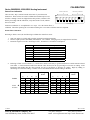
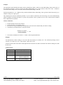
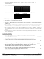
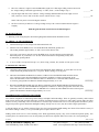
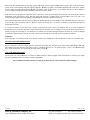
Installation / Troubleshooting Manual
Marine Cruisemaster Bosch, Diesel, K Series, U.S & Metric
This manual (part # 4001-406-05) applies to the following product part numbers:
1)
2)
3)
4)
5)
6)
7)
8)
9)
10)
11)
12)
13)
14)
15)
16)
17)
18)
19)
63080-BOS2K
65040-2012K
65040-2312K
65040-BOS2K
6505-201-2K
6505-BOS-2K
65080-2312K
65080-BOS2K
6510-201-2K
6510-231-2K
6510-BOS-2K
65160-2312K
65160-BOS2K
6520-231-2K
6520-BOS-2K
6532-231-2K
6532-BOS-2K
6710-BOS-2K
6720-BOS-2K
3/31/2004
FloScan Instrument Company, Inc.
3016 NE Blakeley Street, Seattle, WA 98105
4001-391-26
Tel: (206) 524-6625
email: [email protected]
Fax: (206) 523-4961
http://www.floscan.com
Flow Homogenizer Can Replacement
1. Remove the old Flow Homogenizer
can. A Claw type oil filter wrench, or
pipe wrench may be needed.
Aluminum Base
2. Remove the Brass Tube Subassembly
and, Debris Screen, (If used) from the
old can. Install them in new can.
3. Put a coating of grease on the new
Flow Homogenizer’s rubber sealing
washer.
Tube Assembly
P/N 4001-250-00
4. Clean the Aluminum base and put a
coating of grease on the seal’s mating
surface.
5. Place new Flow Homogenizer can on
its Aluminum base. Turn until
“Finger tight”.
Rubber Sealing Washer
6. Using a band type oil filter wrench,
carefully rotate the can until tight,
approximately ¾ of a turn past finger
tight.
•
ATTENTION
Position a strip of rubber, (Bicycle
tube or rubber glove) between the
wrench and can. The rubber both
increases friction and protects the
can. Use caution as over-tightening
will buckle or collapse the can.
This is NOT a FILTER
FloScan
MOUNT WITH ARROWS UP
Flow Homogenizer Can
P/N 4001-199-03
5/14/2003
FloScan Instrument Company, Inc.
3016 NE Blakeley Street, Seattle, WA 98105
7000-144-01
Tel: (206) 524-6625
Fax: (206) 523-4961
email: [email protected] http://www.floscan.com
Lo-Flo Pulsation Damper Can Replacement
FloScan
233-041-00
MOUNT WITH ARROWS UP
Rubber Sealing
Washer
Aluminum Base
Forward Sensor
FloScan
233-041-00
MOUNT WITH ARROWS UP
Rubber Sealing
Washer
Aluminum Base
Return Sensor
1. Remove the old Pulsation Damper can. A Claw type oil filter wrench, or pipe wrench may be needed.
2. Put a coating of grease on both sides of the new Pulsation Dampers’ rubber sealing washer.
3. Clean the Aluminum base and put a coating of grease on the seal’s mating surface.
4. Place the new Pulsation Damper can on its Aluminum base. Turn until “Finger tight”.
5. Using a band type oil filter wrench, carefully rotate the can until tight, approximately ¾ of a turn past finger
tight.
• Position a strip of rubber, (Bicycle tube or rubber glove) between the wrench and can. Rubber increases
friction and protects the can. Use caution as over-tightening will buckle or collapse the can.
White Replacement K-Series Pulsation Damper Can P/N 233-041-00.
4/23/2003
FloScan Instrument Company, Inc.
3016 NE Blakeley Street, Seattle, WA 98105
7000-145-01
Tel: (206) 524-6625
Fax: (206) 523-4961
email: [email protected] http://www.floscan.com
Hi-Cap Pulsation Damper Can Replacement
FloScan
FloScan
233-041-00
233-041-00
MOUNT WITH ARROWS UP
MOUNT WITH ARROWS UP
Rubber Sealing
Washer
Rubber Sealing
Washer
Aluminum Base
Aluminum Base
FloScan
Return Sensor
Forward Sensor
1. Remove the old Pulsation Damper can. A Claw type oil filter wrench, or pipe wrench may be needed.
2. Put a coating of grease on both sides of the new Pulsation Dampers’ rubber sealing washer.
3. Clean the Aluminum base and put a coating of grease on the seal’s mating surface.
4. Place the new Pulsation Damper can on its Aluminum base. Turn until “Finger tight”.
5. Using a band type oil filter wrench, carefully rotate the can until tight, approximately ¾ of a turn past finger
tight.
• Position a strip of rubber, (Bicycle tube or rubber glove) between the wrench and can. Rubber increases
friction and protects the can. Use caution as over-tightening will buckle or collapse the can.
White Replacement K-Series Pulsation Damper Can P/N 233-041-00.
4/23/2003
FloScan Instrument Company, Inc.
3016 NE Blakeley Street, Seattle, WA 98105
7000-145-01
Tel: (206) 524-6625
Fax: (206) 523-4961
email: [email protected] http://www.floscan.com
!
INSTALLATION PLANNING
!
READ ME FIRST - Detailed Mechanical & Electrical Planning Saves Installation Hours!
FloScan K Series systems are not difficult to install. Installation requires only basic electrical & mechanical skills. With forethought
and planning, your system will be installed with few problems. Todd Walker, Yacht Electric Co., (954) 325-9091 regularly installs
FloScan K Series Twin Diesel Systems in about 10 hours. Difficult installations may take several hours longer.
I. Installation Preparation:
Review the pre-installation booklet, mechanical installation instructions, and survey your vessel. Determine where the Sensor(s),
Sensor Assemblies, Switches and Instruments are to be mounted. Place them at their approximate locations. Determine fitting size and
types required for each plumbing connection, (JIC, SAE, NPT, NPTF, or Hose Barb).
FloScan K-Series Hi-Cap Diesel Forward Sensor Assemblies have 1” Female NPT ports.
FloScan K-Series Hi-Cap Diesel Return Sensor Assemblies have 1” inlet and ½” outlet Female NPT ports.
FloScan Hi-Flo, (-10) Diesel and Gasoline Sensors have ½” Female NPT ports.
FloScan K-Series Lo-Flo Diesel and Gasoline System Components, (Sensors and Pulsation Dampers) have ¼” Female NPT ports.
Review the electrical installation instructions. Open and survey your vessels wire ways. Determine if it would be easier to run a 3conductor cable from each sensor to the instrument, or install a junction box, (J-Box) with terminal strip in the engine room. The JBox requires a 4-conductor cable from it to the instrument, and a 3-conductor cable from each sensor. Measure cable lengths from
sensor(s) to J-Box, (If used) to Instrument. Tachometers require a separate 2-conductor cable. If there’s an existing tachometer, its
signal wires can be used.
II. Mechanical Installation:
Install or mount the Sensor(s) or Sensor Assemblies, Instruments and Switches, (Reset, MPG).
III. Plumbing:
Most K Series and -10 installations do not require additional fuel hose. Mount the sensor(s) or sensor assemblies where they’re to be
installed. On installations using Fabric Braid A-1 Fuel Hose install the correct HB X MNPT fitting into each sensor or sensor
assembly. Always assemble fittings using a fuel proof pipe thread sealant. Never use Teflon Tape. Use a hose cutter or knife to cut
the fuel hose. Next install the hose onto the barb fittings. Hose should not be twisted, have adequate slack, an ample radius at all bends
and be supported at reasonable distances, approximately 2-4 feet. When clamping hose onto the barbs, use 2 narrow or 1 wide
stainless hose clamp on each hose end.
Wire Braid A-1 Aeroquip Type Fuel Hose or Hydraulic Hose: Mount the sensor(s) or sensor assemblies where they’re to be
installed. Mark the hose where it is to be cut. Remove hose and bring it to a hydraulic shop. Have them cut the hose and install hose
ends. Reinstall the hoses and install the correct fitting into each sensor or sensor assembly. Always assemble fittings using a fuel proof
pipe thread sealant. Never use Teflon Tape. Hoses should not be twisted, have adequate slack, an ample radius at all bends and be
adequately supported at reasonable distances, approximately 2-4 feet. AP-50 copper sealing washers, (Connie Seals) or Flaretite seals
may be required to seal JIC & SAE fittings.
IV. Electrical Installation:
Run cables between Sensor(s), J-Box, (If used) and Instrument(s). Cables must be adequately supported at reasonable distances,
approximately 2-4 feet.
Wire Terminations—Referring to the wiring diagram. Connect Sensor, Instrument and Switches to their respective wires with crimp
type butt or ring connectors. Always cover connectors and wire ends with heat shrink tubing.
5/14/2004
FloScan Instrument Company, Inc.
3016 NE Blakeley Street, Seattle, WA 98105
4001-386-02B
Tel: (206) 524-6625
Fax: (206) 523-4961
email: [email protected] http://www.floscan.com
V. Pre-Startup:
Prime the fuel system. If you have an electric priming or boost pump, circulate fuel for 10 minutes while checking for leaks. If not, use
the engines manual pump. Before starting, open the lift pumps’ outlet fitting slightly. Before start-up, verify that all fuel system
fittings are tight.
VI. System Start-Up:
Start and run your engines. Look for leaks and other installation problems. If system is not operating properly refer to the
Troubleshooting Instructions and correct any deficiencies.
VII. Calibration:
When system is running properly, refer to the calibration instructions and calibrate your system. If installed properly, initial calibration
takes less than 1 hour. After consuming some fuel, final calibration should only take a few minutes.
USCG approved fuel hose with either fabric or wire reinforcing braid meet the following standards:
Hose Marking
USCG Type A-1
USCG Type A-2
USCG Type B-1
USCG Type B-2
Permeation Rating
100g/m²/24hrs.
300g/m²/24hrs.
100g/m²/24hrs.
300g/m²/24hrs.
2½ Minute Fire Test
Required
Required
Not Required
Not Required
Table I
5/14/2004
FloScan Instrument Company, Inc.
3016 NE Blakeley Street, Seattle, WA 98105
4001-386-02B
Tel: (206) 524-6625
Fax: (206) 523-4961
email: [email protected] http://www.floscan.com
Installation Do’s & Don’ts
Do
Don’t
Use a Fuel Proof Pipe Thread Sealant when
assembling fittings into fuel system components,
(Locktite PST, Leak-Lock, or equivalent).
Never use Teflon Tape!
Don’t use Push-Lok, or Barb-Tite fittings.
Use thin wall, low pressure, full flow type NPT or
Avoid using JIC or SAE swivel fittings. If used
NPTF hose barb fittings.
always install copper conical sealing washers,
(Connie seals) or fitting seals on fittings.
Double clamp all hose barb fittings.
Avoid using 90º elbow fittings.
Install Sensor(s) at a low point in the fuel system, as
far from the engine as practical. Fuel must travel, If possible, avoid bolting or mounting sensor(s)
“Up-hill” slightly after leaving the sensor. Verify directly onto the engine.
correct orientation and fuel flow direction.
Install Forward Sensors on the Fuel Pumps’ Inlet or If on the Pressure Side, Limit Sensor System
Vacuum side, and not on the pressure side.
Operating Pressure to 20 PSI or Less.
Always use 30-micron primary filters.
Avoid 2 or 5 micron primary filters.
Wire with Shielded Cable. Use a dedicated shielded Never use unshielded wires on Magnetic Pickup
pair for Magnetic Pickup Tachometer Senders.
Tachometer Senders.
Connect all, “Ground” wires to a Ground Buss, or
directly to the Battery’s Negative Terminal. Connect Never connect Instrument or Sensor “Ground”
wires to the hull, engine block, or other
or, “Ground” wire shields to the engine block.
machinery.
On Instruments with a GPS interface, connect
Do not connect FloScan’s Data (–) to the GPS
FloScan’s Data (+) to the GPS signal output.
Data (–).
Connect Data (–) to the GPS signal ground.
Always use non-illuminated switches for Totalizer
Reset, Port/Starboard Select, Hours/Synch, and
GPH/MPG.
5/14/2004
FloScan Instrument Company, Inc.
3016 NE Blakeley Street, Seattle, WA 98105
Never use illuminated, or back-lit switches.
4001-386-02B
Tel: (206) 524-6625
Fax: (206) 523-4961
email: [email protected] http://www.floscan.com
INSTALLATION
MECHANICAL & WIRING OVERVIEW, (K Series & -10 Systems)
To Ensure System Accuracy, Follow All Installation Instructions.
•
Sensor Placement. Determine where the Flow Sensor, or Flow Sensor-Pulsation Damper assembly is to be installed. Install the
sensor, or sensor-pulsation damper assembly so that the two fuel flow arrows, (Î Î) or the, (IN and OUT) markings are on a
horizontal plane. All orientation arrows, (Ï) must be pointing up. The forward sensor or forward sensor-pulsation damper
assembly must be installed downstream of the primary filter. Do not install the sensor or either sensor assembly at a high point in
the fuel system. This could negatively impact system accuracy by trapping air. The fuel return line between the return sensors’
outlet port and fuel tank should be at least 12” long and have a 1 to 2” upward rise. This keeps the return sensor flooded,
improving accuracy. Place sensor assemblies in a protected location away from water spray.
Forward Sensor &
Pulsation Damper
Assembly
Return Sensor &
Pulsation Damper
Assembly
FloScan
Inlet
Outlet
FloScan
Forward Sensor
And Pulsation
Damper Assembly
Inlet
Outlet
233/ 236-1K & 2K
Outlet
Inlet
233/ 236-2K
Return Sensor
And Pulsation
Damper Assembly
FloScan
FloScan
Outlet
Inlet
201/ 231-1K & 2K, 235-2K
Inlet
FloScan
201/ 231/ 235-2K
Outlet
Outlet
Inlet
233C-10 & 233D-10 (Cummins PT Systems)
8/5/2003
FloScan Instrument Company, Inc.
3016 NE Blakeley Street, Seattle, WA 98105
ARROW UP
231-10 (Cummins PT Systems)
4001-325-00F
Tel: (206) 524-6625
Fax: (206) 523-4961
email: [email protected] http://www.floscan.com
•
Determine fitting type & size. Minimize the number of elbows and fittings. If swivel fittings are used, (JIC or SAE) their mating
surfaces must be sealed with Copper Conical Sealing Washer, (Connie Seals) or fitting seals. Fitting seals may be purchased
through Fittings Inc. in Seattle, WA (206) 767-4670, 1-800-552-0632, or a local hydraulic supply house.
•
Select Instrument Mounting Location. The instruments’ face is waterproof and a gasket is provided to seal its bezel to the
control panel. Choose a location away from the compass. Install 65/6600 series instruments 12” away from compass. Choose a
shaded location since direct sunlight may cause the LCD display to temporarily turn. This does not damage the LCD, but makes it
impossible to read until cooling down. Make a cutout in the instrument panel for the instrument. The instruments’ maximum
depth is 3 ½” minus the thickness of the console panel.
Instrument Series
6500/6600
7500/7600, 8500/8600, 9500/9600, TwinScan
•
Cutout Size
3 1/16”
3 3/8”
Wiring. Determine wiring run length and the number of switches needed, (always use good quality marine grade switches). Use
18 AWG conductors on runs under 50’. 16 AWG for runs over 50’.
•
Run & Connect Wires. Wire one system at a time. Always begin with the Black, “Ground” wires. Each Black sensor wire must
be connected to the Black, “Instrument Ground” wire. Use a single wire to connect these Black wires to the battery’s negative
terminal, or to the ground buss. For the system to operate properly the, “Ground” wires must be connected in this manner.
Connect other wires per the wiring diagram. Leave the RED, power wire for last.
•
Tachometer Installation Options. 75’7600, 85/8600, and 95/9600 series tachometers require one or two additional wires. If your
engine isn’t equipped with a tachometer sender determine which type it requires, (AC Signal Generator or Magnetic Pickup) and
install one. Some engine alternators produce a tachometer signal and can be used as the tachometer sender. Mechanically driven
AC signal generators and magnetic pickups are available from FloScan and most marine dealers. Hewitt, Motorola, VDO and
Stewart Warner are some of the more common brands.
1.
Keep Existing Tachometer(s). Connect the FloScan tachometers’ Yellow and Violet signal wires to the existing tachometer.
If the tachometer sender wire(s) are not marked, trace them from the tachometer sender up to the existing tachometer. If one
sender lead is grounded, connect the FloScan tachometers Yellow signal wire to the ungrounded lead or terminal. Connect
the VIOLET wire to a Ground Buss, or Battery Minus.
8/5/2003
FloScan Instrument Company, Inc.
3016 NE Blakeley Street, Seattle, WA 98105
4001-325-00F
Tel: (206) 524-6625
Fax: (206) 523-4961
email: [email protected] http://www.floscan.com
2.
Replace Existing Tachometer(s). FloScan MFI instruments have a 3 3/8” outside diameter. This is a common size and fits
into most instrument mounting holes. Identify the engines’ tachometer sender wires. Connect the FloScan tachometers’
Yellow and Violet signal wires to the sender wires. If one sender lead is grounded, connect the FloScan tachometers Yellow
signal wire to the ungrounded lead or terminal. Connect the VIOLET wire to a Ground Buss, or Battery Minus.
3.
New Tachometer(s). Run a dedicated shielded pair of wires between the instrument and tachometer sender, (This is
especially important with Magnetic Pickup senders). Ground the shield only in the engine room.
•
Magnetic Pickup & AC Signal Generator Tachometer Senders: Connect the FloScan tachometers’ Yellow signal wire to
one sender terminal. Connect the Violet wire to the other terminal.
Engine Alternators: Connect the FloScan tachometers Yellow signal wire to the alternators’ tachometer output terminal.
This terminal is usually marked as TACH, or SIG. Connect the VIOLET wire to a Ground Buss, or Battery Minus.
•
•
Pre-Startup & Installation Check. Prime the fuel system. If you have an electric priming or boost pump, circulate fuel for 10
minutes while checking for leaks. If not, use the engines manual pump. Before starting, “Crack” the lift pumps’ outlet fitting
slightly. Continue pumping until system is fully primed. Before start-up verify that all fuel system fittings are tight.
•
System Start-Up. Start and run your engines. Survey the installation for leaks and other problems. If the system is not operating
properly refer to the Troubleshooting Instructions and correct any deficiencies. When the engine reaches operating temperature
increase engine speed to about 1500-2000 RPM. Letting it run for five or ten minute’s helps purge residual air from the system.
•
Any vacuum leaks between the fuel tank and lift pump will allow air to be drawn into the system. These leaks cause high and/or
fluctuating GPH readings. Only severe leaks affect engine performance, but all leaks affect sensor performance and instrument
readings. Vacuum or suction leaks occur at improperly sealed primary filters, loose packing nuts on cross over & shut off valves
and improperly sealed fittings. Vacuum leaks can also occur from corroded copper fuel lines and chaffed fuel hose, (where it rubs
against bulkheads or engine parts). To verify that a suction leak is present, temporarily insert a clear piece of fuel resistant tubing
downstream of the Forward Sensors’ outlet. Observe the clear hose for at least two minutes looking for bubbles. Bubbles can
appear as a constant stream of small bubbles, or as an occasional larger bubble. Tighten all possible leak sources, grease primary
filter seals and install fitting seals on JIC/SAE fittings. Continue to observe the clear tubing until it runs clear without any
bubbles. Flex or wiggle rubber hose sections while observing the clear tubing. If bubble volume increases inspect the hose and
check its fittings. Repair as necessary.
•
When idling in neutral, (No Load) GPH fluctuations can also be caused by the governor trying to maintain a steady engine RPM.
•
Calibration. When the system is running properly, refer to the calibration instructions and calibrate your system. If installed
properly, initial calibration takes much less than 1 hour. After consuming some fuel, final calibration should only take a few
minutes.
8/5/2003
FloScan Instrument Company, Inc.
3016 NE Blakeley Street, Seattle, WA 98105
4001-325-00F
Tel: (206) 524-6625
Fax: (206) 523-4961
email: [email protected] http://www.floscan.com
INSTALLATION
Fuel Flow Schematic - Low Flow Diesel Systems (BOS, 201, 231 & 235-2K)
OUT
30 Micron
or Coarser
Filter
Forward Sensor
And Pulsation
Damper Assembly
OUT
IN
IN
**
Bottom view of Pulsation Damper
FloScan
Engine
Return Fuel
Cooler
**
Return Sensor
And Pulsation
Damper Assembly
Tank
FloScan
**
Fuel Flow Direction
*Caution: Diesel System Components are not designed for use on Gasoline Fuel Systems.
FloScan Sensor & Pulsation Damper Plumbing Guidelines:
1. Install flow sensor & pulsation damper assemblies with their orientation arrows pointing UP Ï. Fuel must
enter through the port marked IN, or with an inward pointing arrow, (ÎÍ) and exit through the port
marked OUT, or with an outward pointing arrow, (ÍÎ). Install the sensor – pulsation damper assembly as
far from the engine as practical. Maximizing fuel line length between engine and sensor – pulsation damper
assembly improves instrument accuracy. Pipe plugs are provided to block unused ports. Refer to Pulsation
Damper ** Bottom View.
2. Maintaining high flow velocities through the fuel lines minimizes sensor oscillations. Use the smallest
approved fuel line diameter for your engine, especially on the return line. Consult the engine owners’
manual for more information. To insure that the return sensor remains flooded, install the return sensor –
pulsation damper assembly at a low point in the system. Fuel should travel “Up-Hill” upon exiting the return
sensor.
3. Flow sensors must always be installed downstream of a filter or debris screen (no finer than 30 micron).
Particles larger than 1200 microns may jam the sensors’ rotor and cause it to fail.
4/23/2003
FloScan Instrument Company, Inc.
3016 NE Blakeley Street, Seattle, WA 98105
4001-309-02
Tel: (206) 524-6625
Fax: (206) 523-4961
email: [email protected] http://www.floscan.com
FloScan Low Flow 2K Diesel System Kits
Forward Flow
Return Flow
KIT
Sensor
Sensor
TYPE
201
201
201-2K
231
201
BOS-2K
231
231
231-2K
*235
*235
*235-2K
4. Flow sensor model numbers are molded into the colored plastic wire cap. Sensors are shipped in matched
pairs. They must not be mixed on twin engine installations. Match codes are identified by a single standalone letter stamped into the sensor body, or from a colored sticker.
5. Model *235 sensors are temperature compensated and stamped with their Instruments serial number, xxxxF
(Forward), xxxxR (Return). *235-2K Temp-Comp sensor kits are precisely calibrated and matched to each
instrument. Sensors are labeled FORWARD and RETURN and must be installed in these positions for
proper operation. The instrument head serial number must match the flow sensor(s) serial number.
6. If there’s a shut-off valve in the return line, do not operate the engine with it closed. Fuel system pressure
could exceed the system working pressure of 40 PSI, and may cause a catastrophic system failure. You
should either tag the valve so the engine will not run when it is closed for maintenance, or bypass it with a
relief valve.
NOTE: Minimize the number of 90º elbows and pipe fittings. Excessive use may create a high vacuum, fuel
restricting, pressure drop across the forward part of the fuel system. Refer to the engine owners’ manual
for maximum fuel pump inlet vacuum. A vacuum gauge can be used to confirm that the system is within
limits.
CAUTION: DO NOT OVER TIGHTEN FITTINGS. Torque sensor and pulsation damper pipe thread
fittings to a maximum of 15 ft.-lb. (180 inch-lb.), or 2 full turns past hand tight, whichever comes
first. Leak Lock pipe thread sealant is provided with your system. Use it on all pipe thread fittings.
DO NOT USE TEFLON TAPE.
4/23/2003
FloScan Instrument Company, Inc.
3016 NE Blakeley Street, Seattle, WA 98105
4001-309-02
Tel: (206) 524-6625
Fax: (206) 523-4961
email: [email protected] http://www.floscan.com
ELECTRICAL
Series 5500(0)/56100/5800(0)/6500(0) CruiseMaster,
All Multi Function Instruments, & TwinScan®
SET UP
Wire & Switches: Use 18 AWG stranded wire on runs under 50’. For runs over 50’ use 16 AWG, (Shielded wire is recommended for
all Diesel systems, and suggested for Inboard & I/O gasoline systems. Always, “Ground” wire shield or shield drain wire in the
engine room by connecting it to the bonding system, or engine block). The double wiring harness for twin engine Pulse/NMEA Diesel
installations is included in all, (97/9800(0)) kits. FloScan suggests using J-Boxes, Terminal Blocks, and three conductor cables
between the sensors and instrument to make wiring easier.
Install Single Pole Single Throw (SPST) switches for Totalizer Reset, Port–Starboard Select, Engine Hours / Synchronizer, and GPH /
MPG, (switches are not included in kit). To determine which switch types are required for your system, refer to the table below. All
instruments except TwinScan Tachometers require a totalizer reset switch.
SYSTEM
2500
5500
5800
6500/6600
ALL 7XXX or 8XXX MFI
All 9XXX MFI
TwinScan GPH
TwinScan Tach
NA = Not Applicable
TOTALIZER RESET
SPST or Momentary ON
SPST or Momentary OFF
SPST or Momentary OFF
SPST or Momentary OFF
SPST or Momentary ON
SPST or Momentary ON
SPST or Momentary ON
NA
PORT/STBD (Twin
Systems)
SPST
SPST
NA
SPST Twin
Cummins (PT) only
SPST
SPST
NA
NA
HOURS/
SYNCH
NA
NA
NA
NA
GPH/
MPG
NA
NA
NA
NA
MPG/
SYNCH
NA
NA
NA
NA
SPST
SPST
NA
NA
NA
SPST
NA
NA
NA
NA
SPST w/ both
GPH & Tach
Grounding: Each Black sensor wire must be connected directly to the Black, “Instrument Ground” wire. Use a single wire to connect
the Black wire junction to the battery’s negative terminal, or a ground buss.
Power: FloScan Instruments & sensors operate on 9 to 12 VDC. Voltages exceeding 16 VDC will damage the equipment. 24 & 32
VDC systems must be reduced to 12 VDC. Two different types of voltage reducers are available through FloScan.
CONNECT THE WIRES
Installation: Connect wires one at a time and Install heat shrink before proceeding to
the next wire, (refer to wiring diagram). Connect ground wires first, (BLACK
instrument ground wire to the BLACK sensor wires. Connect this junction to the
battery’s negative terminal or the ground buss). Connect all other wires leaving the
Red power wires for last to prevent short circuits during the installation.
Splicing: Splice or join individual wires per the diagram. Slide heat shrink tubing over
the splices to prevent shorts. Do not seal splices until the installation is finished and
has been tested.
1. Slide heat shrink tubing
over one wire.
2. Insert wire ends into butt splice.
3. Crimp butt splice.
4. Slide heat shrink tubing
over butt splice.
HEAT
5. Apply heat.
An adequate number of crimp-on connectors and heat-shrink tubing are included with
system. The heat-shrink is a special type that will bond to wire insulation and make a
watertight connection. See diagram for proper tubing application. Crimp-on connectors are sized for 18 or 20 gauge stranded wire.
FINAL ACTIONS
Check Electrical Installation: Test all connections. Support and secure all dangling wires. Start engine and calibrate system.
9/19/2003
FloScan Instrument Company, Inc.
3016 NE Blakeley Street, Seattle, WA 98105
4001-100-00H
Tel: (206) 524-6625
Fax: (206) 523-4961
email: [email protected] http://www.floscan.com
ELECTRICAL
Series 6500 / 6600, 65000 / 66000 GPH Cruisemaster
To ensure years of trouble free operation, please read these
instructions carefully before beginning your installation
Your Cruisemaster is supplied with a sufficient number of crimp-on and heat-shrink
tubing to make a typical installation. The heat-shrink tubing is a special type that
will bond with the wire insulation to make a water tight connection. See the diagram
to right for proper application of the tubing. The crimp-on connectors work best
with 18 gauge stranded wire (wire not included).
Connect the wires one at a time (see wiring diagram for your particular installation)
and install heat shrink before proceeding to the next wire, saving the RED wire to
+12V until last to prevent short circuits during the installation.
1. Slide heat shrink tubing
over one wire.
2. Insert wire ends into butt splice.
3. Crimp butt splice.
4. Slide heat shrink tubing
over butt splice.
HEAT
5. Apply heat.
NOTE: On installations with two flow sensors, the WHITE wire MUST go to the
Forward Flow Sensor and the BROWN wire MUST go to the Return Flow Sensor.
Reversing these wires will cause the instrument to show "O" flow. The RED wire (to +12V Supply) should be connected to the keyed
side of the ignition switch. If power is not being supplied through a fuse panel, a 1 amp fuse should be installed at the source of
power (+12VDC).
SYSTEM MUST BE PROPERLY GROUNDED FOR CORRECT OPERATION
Run a stranded ground wire from the negative terminal of the battery and splice it into the black wire common between the flow
sensor(s) and the instrument head. The Cruisemaster internal circuitry is isolated from the can at the instrument head to prevent
ground loop interference. Connect to ground only at the black wire junction to the flow sensor(s).
The BLUE wire is used for troubleshooting only. Leave disconnected for normal operation. For the Cruisemaster installation a single
pole, single throw (SPST) switch is required (not supplied) to reset the totalizer. A good selection is a (SPST) momentary OFF.
Connect the GREEN wire through the reset switch to a constant +12VDC. The display only uses 70 microamps (.0007 amps) of
power, so it will not appreciably drain your batteries even for an extended period of time. If your boat is equipped with a MASTER
BATTERY SWITCH and you do not want to lose the totalizer memory, you will need to run a power wire through a 1/4 amp fuse to
the battery. The fuse is to protect the wiring and should be as close to the battery as possible.
Connect one BLACK wire from the illumination bulb to the illumination circuit and the other BLACK wire to instrument ground. It
makes no difference which one gets power.
TO RESET THE TOTALIZER
Select the OFF position of the Totalizer reset switch for approximately 15 seconds. Once the totalizer has been reset to zero, select
the ON position of the Totalizer reset switch for normal operation.
LOCATION OF INSTRUMENT
The series 6500 dial meter requires a 3 1/16" diameter cutout. The instrument contains a magnet which may affect your compass, so
some care is required in choosing its mounting location.
FloScan Instrument Company, Inc.
3016 NE Blakeley Street, Seattle, WA 98105
Tel: (206) 524-6625
Fax: (206) 523-4961
email: [email protected] http://www.floscan.com
WIRING DIAGRAM
Series 5800/58000 6500/65000 6600/66000 Gas/Diesel Cruisemaster
GPH Instrument with LCD Totalizer
WIRE COLOR
RED
GREEN
BLACK
BLUE
WHITE
BROWN
WIRING LEGEND
FUNCTION
Ignition + 12VDC
Totalizer Memory Constant + 12VDC
Instrument Ground
Diagnostic
Forward flow signal
Not Connected (return sensor if utilized)
Diesel engines using only one sensor
Totalizer Memory
Constant+ 12 VDC Source
(Negligible battery draw)
1/2 amp fuse
BLACK
WHITE
RED
GREEN
Totalizer
Reset Switch
(momentary OFF)
* Do not use Back-lit, or Illuminated switches
BLUE (not connected, diagnostic wire)
BROWN (not connected in single sensor installations)
To
Illumination
Circuit
+ 12VDC
1/2 amp fuse
To Ignition Switch
BLACK
(key ON = + 12VDC)
RED
R
W
CABLE
B
WHITE
BLACK
Flow
Sensor
Battery (-) buss
4/17/2003
FloScan Instrument Company, Inc.
3016 NE Blakeley Street, Seattle, WA 98105
4001-372-00D
Tel: (206) 524-6625
Fax: (206) 523-4961
email: [email protected] http://www.floscan.com
Forward and Return Sensor Gasoline EFI & Diesel Engine Installations
Totalizer Memory
Constant+ 12 VDC Source
(Negligible battery draw)
BROWN
RED
WHITE
BLACK
GREEN
Totalizer
Reset Switch
1/2 amp fuse
(momentary OFF)
* Do not use Back-lit, or Illuminated switches
To Ignition (Key ON = + 12VDC)
To
Illumination
Circuit
+ 12VDC
BLACK
1/2 amp fuse
BLACK
Battery (-) buss
CABLE
BLUE (not connected, diagnostic wire)
B
BLACK
R
R
B
W
CABLE
B
W
Forward
Flow
Sensor
WHITE
RED
R
R
BROWN
WHITE
B
B
W
CABLE
B
W
Return
Flow
Sensor
NOTE: For twin engine installations, you will repeat the wiring shown above for each engine.
4/17/2003
FloScan Instrument Company, Inc.
3016 NE Blakeley Street, Seattle, WA 98105
4001-372-00D
Tel: (206) 524-6625
Fax: (206) 523-4961
email: [email protected] http://www.floscan.com
CALIBRATION
Series 5800/58000, 6500/65000 Analog Instrument
Return Flow Calibration
Totalizer Calibration
There are nine, “Dip” switches located on the back of your 6500 Series
Instrument. These switches are used to calibrate the instrument prior to use.
Switches 1 through 7 and 9 are shipped in the OFF position, switch 8 is ON.
Before proceeding with the calibration, verify that switch 8 is ON, and that
the rest are OFF.
Return Flow Calibration
ON
1
2
3
4
5
6
7
8
9
Meter Damping
Instrument calibration is accomplished in two steps. First the Return Flow is
calibrated. Then after operating the vessel and consuming one or two tanks of fuel the totalizer is adjusted.
Return Flow Calibration:
Referring to Tables 1 and 2, do the following to calibrate the return flow sensor.
1.
2.
3.
Start your engine. Let it idle until it reaches its normal operating temperature.
Increase engine speed to 1800 RPM, (Unloaded) for 1 or 2 minutes. This purges any air trapped in the fuel lines.
Return the engine to low idle. Referring to table 1, determine its’ no load fuel consumption.
Table 1
HP
100-400
400-750
750-1000
1000-1250
1250-1500
1500-2000
2000-3000
4.
No Load Idle Consumption
Non-Turbo
w/Turbo
0.1-0.5 GPH, (1-2 LPH)
0.3-0.7 GPH, (2-3 LPH)
0.8 GPH, (3 LPH)
1.0 GPH, (3-4 LPH)
1.0 GPH, (4 LPH)
1.5 GPH, (5-6 LPH)
2.0 GPH, (7-8 LPH)
2.5 GPH, (9-10 LPH)
3.0 GPH, (11-12 LPH)
3.5 GPH, (13-14 LPH)
3.5 GPH, (13-14 LPH)
4.0 GPH, (15-16 LPH)
4.5 GPH, (17 LPH)
5.0 GPH, (18-19 LPH)
Referring to Table 2, turn switches 6, 7, 8 and 9 ON or OFF, as necessary to get the instrument to read the amount selected
from Table 1. If the instrument reads lower than the value selected, use the (+) percentages to increase its reading. If the
instrument reads higher than the value selected, use the (-) percentages to decrease its reading. Begin by adding, or
subtracting 0.5% from the reading. Continue in 0.5% increments until the desired reading is obtained.
Switches
Table 2
Initial Î
Position
6
Off
On
Off
On
Off
On
Off
On
7
Off
Off
On
On
Off
Off
On
On
8
Off
Off
Off
Off
On
On
On
On
7/14/2003
FloScan Instrument Company, Inc.
3016 NE Blakeley Street, Seattle, WA 98105
Change
factor
9
Off
Off
Off
Off
Off
Off
Off
Off
-2.0%
-1.5%
-1.0%
-0.5%
0%
+0.5%
+1.0%
+1.5%
Switches
6
Off
On
Off
On
Off
On
Off
On
7
Off
Off
On
On
Off
Off
On
On
8
Off
Off
Off
Off
On
On
On
On
Change
factor
9
On
On
On
On
On
On
On
On
+2.0%
+2.5%
+3.0%
+3.5%
+4.0%
+4.5%
+5.0%
+5.5%
4001-317-00D
Tel: (206) 524-6625
Fax: (206) 523-4961
email: [email protected] http://www.floscan.com
Example:
The instrument reads 0 GPH after the engine warms up. Referring to Table 2, add 0.5% to the GPH reading, (Turn switch 6 ON). If
the instrument continues to read low, increase the GPH reading another 0.5%, (Turn switches 6 OFF, and 7 ON). Continue to
increase the GPH reading in 0.5% increments until the desired GPH reading is achieved.
Fuel flow fluctuations of .1 to .2 GPH are fairly common on Marine Diesels when idling. Some governors tend to hunt as they try to
maintain a steady, low engine speed.
This completes the return flow calibration procedure. If you’re unable to obtain the correct idle setting, refer to the Troubleshooting
guide for guidance in locating the problem. If you have any questions or have a problem you can’t solve, call the FloScan Technical
Service Department for assistance.
Totalizer Calibration:
1.
2.
3.
4.
Fill the fuel tank(s) and reset the totalizer.
Operate the boat as you normally would.
Do at least two fill ups and determine the difference between the fuel consumed and your totalizer reading.
Calculate the percentage difference, using this formula:
Difference in Gallons
x 100
Totalizer Reading
5.
Turn ON the combination of switches 1, 2 and/or 3 which equal that difference.
Example:
You determine the totalizer reading is 6.5% lower than what actually was actually used. The combined percentage total of
switches 1 (2%) and 2 (4%) is 6%. Turn switches 1 and 2 and “4” ON.
Switch #4 remains OFF if the totalizer reads higher than the actual fuel used, and is turned ON if the totalizer reading is less than
the fuel used.
Switch Positions:
Switch position
(1)
(2)
(3)
(4)
(5)
Amount of compensation
2%
4%
8%
OFF
Totalizer reading higher
ON
Totalizer reading lower
OFF
Normal meter damping
ON
Heavy meter damping
7/14/2003
FloScan Instrument Company, Inc.
3016 NE Blakeley Street, Seattle, WA 98105
4001-317-00D
Tel: (206) 524-6625
Fax: (206) 523-4961
email: [email protected] http://www.floscan.com
TROUBLESHOOTING
Series 5800-58000, 6500/65000, 6600/66000 CruiseMaster GPH/LPH Instrument
BEFORE CALLING FOR ASSISTANCE, COMPLETE THESE TROUBLESHOOTING CHECKS AND RECORD YOUR FINDINGS.
TECHNICAL SUPPORT REQUIRES THIS INFORMATION BEFORE A RETURN AUTHORIZATION WILL BE ISSUED. IT TAKES ABOUT
20 MINUTES AND IS VERY IMPORTANT IN ANALYZING SYSTEM PROBLEMS.
Before starting record the Instrument MODEL # ________________________ and all Switch settings.
ON
OFF
Switch Settings
1
FAULT
Blank LCD Display.
No Back-Lighting.
Low Totalizer Reading, more than 10%.
High Totalizer Readings, more than 10%.
Fluctuating GPH readings.
No GPH or Totalizer reading.
No Forward or Return Sensor readings.
High Forward or Return Sensor readings.
2
3
4
5
6
7
8
9
PROBABLE CAUSE
SEE SECTION:
Wiring
Wiring/bulb failure
Calibration
Sensor orientation/failure
Incorrect/defective sensor
Incorrect switch settings
Suction leak
Suction leak
Low RPM operation
Wiring/Instrument failure
Sensor orientation/failure
Wiring
Sensor failure
Suction leak
Wrong switch settings
Sensor orientation
Section I
Section III
Calibration sheet
Installation Sheet
Operations
Manual page
Section VI
Section VI
Section VIII
Section IV and V
Installation sheet
Section IV and V
Section II
Section VI
Calibration sheet
Section VII
I. INSTRUMENT HEAD DIAGNOSTIC TEST:
1.
Referring to the wiring diagram, verify that Instrument & Sensor(s) are wired correctly.
2.
Verify that all wiring connections are tight and not corroded. Check continuity with an ohmmeter.
3.
With power switched ON, measure voltage between the RED and BLACK wires,
(Take readings on the Instrument side of the butt splice connections).
__________VDC
The voltage reading should be between 12 and 14.5 VDC. Proceed to step 4 if it is, if not:
a. Check for voltage between the RED wire and another ground point.
b. If voltage is present, trace along the BLACK wire until its’ open connection is found.
c. If no voltage is present, trace the RED wire until its’ open connection is found.
4.
With switched power ON slide, “Dip” switches 1-9 to the ON, or UP position. This places the
Instrument into diagnostic mode.
NOTE: If the LCD display is blank, verify that the totalizer reset switch, (Connected between the GREEN
wire and +12 volts) is in the ON position. Verify that 12 VDC is present between both switch
terminals and the Black wire. Next check the, “Green wire” fuse.
4/17/2003
FloScan Instrument Company, Inc.
3016 NE Blakeley Street, Seattle, WA 98105
4001-103-00F
Tel: (206) 524-6625
Fax: (206) 523-4961
email: [email protected] http://www.floscan.com
5.
In, “Diagnostic Mode” the totalizer will count at 1 gallon or 1 liter per second. If it does not, the
instrument is defective.
6.
With the BLUE wire floating, (Disconnected) the pointer should read approximately:
10 GPH models
20 GPH models
32 GPH models
50 GPH models
100 GPH models
7.
9
18
28
45
90
40 LPH models
80 LPH models
160 LPH models
500 LPH models
35
70
140
450
With the BLUE wire connected to the Instruments’ BLACK wire, the pointer should read approximately:
10 GPH models
20 GPH models
32 GPH models
50 GPH models
100 GPH models
0.5
1
2
2
5
40 LPH models
80 LPH models
160 LPH models
500 LPH models
2
5
10
20
NOTE: If readings are significantly Higher or Lower, the Instrument may be defective.
8.
Turn switches 1, 2, 3, 4, 5, 8 and 9 OFF, leave 6 and 7 ON.
9.
Disconnect the WHITE and BROWN wires at the instrument. Connect a course thread, (½ - 13) or similar non-plated bolt to
the BLACK wire.
10. With the BLUE wire disconnected lightly run the WHITE wire up and down the bolt threads. This generates a pulse and
should lift the needle off zero. The totalizer should also eventually start counting. Faster movements give higher readings.
11. With the BLUE wire connected to +12 VDC, lightly run the BROWN wire up and down the bolt threads. This generates a
pulse and should lift the needle off zero. The totalizer should also eventually start counting. Faster movements give higher
readings.
12. If the Instrument passes steps 10 & 11, returns switches 1-9 to their original position and proceed with Part II. If not contact
FloScan Technical Support.
II. TEST FLOW SENSOR(S)
1.
With the engine idling, connect the BLUE diagnostic wire to Ground. The instrument needle will display
fuel flowing through the Forward Sensor
__________GPH
When testing, the scale and readings on 0-10 GPH & 0-40 LPH Instruments increase by a factor of 3.
2.
Connect the BLUE wire to +12 VDC. The instrument will display fuel flowing through the Return Sensor.
___________VDC
3.
4.
5.
With your voltmeter set to a DC scale greater than 14 volts, measure between the RED (+12VDC) and
BLACK (Instrument ground) wires. With engine idling, measure and record the voltage reading.
___________VDC
Move the voltmeters’ negative lead to the WHITE (Signal) wire. With engine idling, measure and record
the voltage reading. It should be approximately 5-7 VDC, about ½ of the reading in step 3.
___________VDC
Stop the engine while observing the voltmeter. Voltage readings should fluctuate between a high of 9 to
12 VDC, and a low of 0 to 4 VDC as the flow sensors’ turbine slows to a stop.
___________VDC
NOTE: This may not be seen on a digital voltmeter.
4/17/2003
FloScan Instrument Company, Inc.
3016 NE Blakeley Street, Seattle, WA 98105
4001-103-00F
Tel: (206) 524-6625
Fax: (206) 523-4961
email: [email protected] http://www.floscan.com
6.
7.
Move the voltmeters’ negative lead to the BROWN (signal) wire. With engine idling, measure and record
the voltage reading. It should be approximately 5-7 VDC, about ½ of the reading in step 3.
___________VDC
Stop the engine and observe the voltmeter. Voltage readings should fluctuate between a high of 9 to 12
VDC, and a low of 0 to 4 VDC as the flow sensors’ turbine slows to a stop.
___________VDC
NOTE: This may not be seen with a digital voltmeter.
8.
The flow sensor may be defective if voltage readings in steps 5 & 7 remain constant when the engine is
stopping.
With this guide in hand, contact FloScan Technical Support.
III. BACKLIGHTING.
1. Referring to the wiring diagram, check back lighting bulb and Instrument illumination circuit.
IV. CHECK + 12 VDC and GROUND
1.
Turn Instrument power ON, and go to the Instruments back side.
2.
Measure between the RED (Power) wire and the BLACK (Instrument ground) wire.
This reading should be approximately 12 VDC, but not lower than 10 VDC.
3.
4.
If 12 VDC is not present, measure between the RED power wire and a known good ground in the
Instrument panel. If you measure 12 to 14 VDC between the Red wire and ground, you may have
an Instrument ground problem.
__________VDC
__________VDC
If 12 to 14 VDC is not present in steps 2 or 3, check wiring, switches, fuse, and the 12 VDC power source.
V. CONTINUITY TESTING
1.
Continuity testing requires access to the back of the Instrument and an Ohmmeter. It verifies that wires are not
broken, shorted to ground, another wire, or to power. Before starting, secure all power.
2.
Disconnect the WHITE and BLACK wire harness conductors from the WHITE and BLACK Port Sensor
wires. Connect a jumper from the WHITE wiring harness conductor to a known good ground. At the
back of the Instrument, connect an Ohmmeter lead to its’ WHITE wire. Connect the other Ohmmeter lead
to a known, good ground. The Ohmmeter should read approximately 0.1 to 3 Ω.
3. Disconnect the BROWN and BLACK wire harness conductors from the WHITE and BLACK Starboard Sensor
wires. Connect a jumper from the BROWN wiring harness conductor to a known good ground. At the back of the
Instrument, connect an Ohmmeter lead to its’ BROWN wire. Connect the other Ohmmeter lead to a known good
ground. The Ohmmeter should read approximately 0.1 to 3 Ω.
____________
(Ohm Reading)
____________
(Ohm Reading)
VI. FINDING FUEL SYSTEM SUCTION LEAKS
Two common complaints are Fluctuating GPH readings, and High Totalizer Readings. These are generally caused by small vacuum
leaks between the fuel tank and fuel pump inlet. Generally, fluctuations tend to be between 2 and 4 GPH. Vacuum leaks also affect
totalizer accuracy, and usually cause it to read about 15 to 100% high. Vacuum leaks can occur in both gasoline and diesel systems.
Larger leaks produce greater fluctuations and higher readings. Except in severe cases, they do not affect engine performance.
A stiff anti-siphon valve or sticking carburetor float valve also cause fluctuating GPH readings, but do not affect totalizer accuracy. If
the totalizer reading is within, (+/- 6%) you should repair or replace defective valve.
Finding suction leaks can be a time-consuming chore. When approached properly, they can be found and repaired quickly. Two
common places for suction leaks to occur are the primary fuel filter/water separator and/or from a loose valve stem packing nut.
4/17/2003
FloScan Instrument Company, Inc.
3016 NE Blakeley Street, Seattle, WA 98105
4001-103-00F
Tel: (206) 524-6625
Fax: (206) 523-4961
email: [email protected] http://www.floscan.com
Remove the filter housing and coat all o-rings, gaskets and sealing surfaces with a medium to heavy grease, (Not oil) and reassemble.
Grease all valve stem packings and gently tighten gland nuts. Do not over tighten, valve handles should be able to turn freely. Tighten
all hose clamps and compression fittings (Do not over tighten). Run the engine for 5 to 10 minutes and observe GPH readings. If
you’ve found the problem, fluctuations should be reduced to less than ½ GPH.
If this does not cure the problem, temporarily insert a clear piece of fuel resistant tubing in the fuel line. On diesel engines, install it
downstream of the forward flow sensor. Run the engine and watch for a constant stream of small bubbles in the clear tube, or an
occasional larger bubble. Sometimes shining a light through the tube makes bubbles easier to see.
Have someone observe the clear tube while you shake any flexible fuel hose(s). If the bubble stream continually increases or decreases
as you do this, you’ve found the leak area. Repair or replace as needed. If it is a one-time occurrence, you probably dislodged air
trapped in the fuel line.
If you haven’t found it yet, the last step is to inspect each pipe joint in the system. You should be able to see joint compound all
around the joint. If you do not, that joint is suspect and needs to be resealed. After re-sealing you may need to run the engine for a few
minutes to purge any remaining air. You should now see bubble free solid fuel running through the clear tube. If you still see bubbles
you missed a leak somewhere, recheck your work. Remove the tube and restore the fuel system to its normal condition.
Fuel Filters:
A dirty fuel filter, or one that is too fine (1-25 micron) will draw vapor bubbles out of the fuel. Replace it with a new 30-micron filter.
VII. FLOW SENSOR ORIENTATION
Sensor orientation is critical for proper operation. All Sensors have their inlet and outlet ports clearly marked (IN / OUT or Î Î).
This identifies fuel flow direction. The Sensor must be, “Plumbed” correctly for it to operate properly. There is an additional single
arrow on the Sensor body. It is crucial that this single arrow point up Ï.
VIII. LOW RPM OPERATION
At idle, under a no load condition, it is common for GPH readings to fluctuate slightly. These fluctuations are caused by the engine
governor regulating fuel flow to maintain a steady engine RPM.
This concludes Instrument and Sensor testing. If problems persist, contact FloScan Technical Support
4/17/2003
FloScan Instrument Company, Inc.
3016 NE Blakeley Street, Seattle, WA 98105
4001-103-00F
Tel: (206) 524-6625
Fax: (206) 523-4961
email: [email protected] http://www.floscan.com