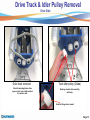
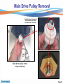
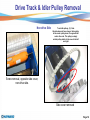
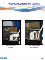
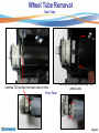
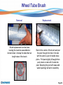
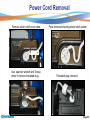
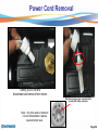
1
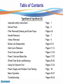
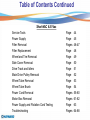
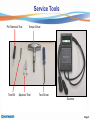
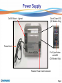
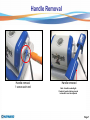
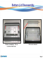
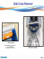
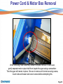
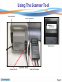
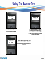
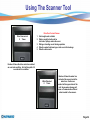
Robotic Cleaner Troubleshooting Guide Copyright 2010 Hayward Industries Inc. Table of Contents TigerShark & TigerShark QC Important safety instructions Service Tools Filter Removal/Cleaning and Drain Flaps Handle Removal Venturi Removal Bottom Lid Disassembly Side Cover Removal Drive Track and Idlers Power Cord and Motor Box Wheel Tube Brush and Bearings Using the Scanner Tool Power Supply and Flotation Cord Testing Basic Operation Troubleshooting Page 1 Page 2 Pages 4-6 Page 7 Page 8 Pages 9-10 Pages 11-12 Pages 13-16 Pages 17-27 Pages 28-30 Pages 31-34 Page 35 Pages 36-37 Pages 38-43 Table of Contents Continued SharkVAC & E-Vac Service Tools Power Supply Filter Removal Filter Replacement Wheel and Tire Removal Side Cover Removal Drive Track and Idlers Main Drive Pulley Removal Wheel Tube Removal Wheel Tube Brush Power Cord Removal Motor Box Removal Power Supply and Flotation Cord Testing Troubleshooting Page Page Pages Page Page Page Page Page Page Page Pages Pages Page Pages 44 45 46-47 48 49 50 51 52 53 54 55-60 61-62 63 64-68 Safety ! Page 1 Service Tools Pin Removal Tool Torx Bit Torque Driver Spanner Tool Torx Driver Scanner Page 2 Power Supply On/Off Switch - Lighted Quick Clean LED (QC Models Only) Power Cord Full Cycle Button and LED (QC Models Only) Flotation Power Cord Connector Page 3 Disassembly – Filter Removal Remove bottom lid by sliding LH and RH latch towards center. Bottom lid removed providing access to filter cartridge assembly Page 4 Filter Removal Note the drain flaps, one per side. Not required to remove for filter cleaning, but visually inspect when filter is removed. Filter cartridge removed Page 5 Filter Removal Note: Elements must be installed with support ribs facing outward Filter cartridge assembly Note: Elements can be cleaned by gently spraying with a garden hose. Be careful not to use high pressure or this may damage the element. Filter elements removed Spring cleanup filter elements. For temporary use in heavy spring cleaning. Page 6 Handle Removal Handle removal 1 screw each end Handle removed Note: Handle is watertight. If water is heard sloshing around in handle it must be replaced. Page 7 Venturi Removal Rotate CCW & lift out Removed, access to impeller Page 8 Bottom Lid Disassembly Bottom lid assembly. Pull up to remove inlet cover. Inlet cover removed Page 9 Bottom Lid Disassembly Inlet flaps, check for free movement. Inlet flaps removed for inspection. Page 10 Side Cover Removal Motor output shaft. Drive end. Motor assembly Power cord Bottom view with bottom lid and filter assembly removed. Power cord end Note: Use Torx bit and power driver for removal. 7 screws each end to remove for side plate removal, drive side. Power cord end, 7 screws. Page 11 Side Cover Removal Screw removal Note that ‘drive side’ or motor output side is side opposite of where power cord enters unit. Side cover removed Page 12 Drive Track & Idler Pulley Removal Drive Side Drive track removed Check for missing/broken drive cogs on inner loop of belt and also for cracks in belt. Track idler pulley (2/side) Bearings should rotate smoothly and freely. Note that flange faces inward. Page 13 Main Drive Pulley Removal Note drive ‘key’ in pulley and how it mates to the output shaft drive pin of the motor. Main drive pulley, motor output side only Page 14 Wheel Tube Removal Carefully pull wheel tube away from other side plate. Roller will slide off track. Both drive tubes removed. Page 15 Drive Track & Idler Pulley Removal Non-drive Side Track idler pulleys, (3). Note this side does not have a keyed drive pulley at the center pulley since it is opposite the motor drive end. This pulley is simply an idler pulley similar to the ones to the left and right. Screw removal, opposite side cover, non-drive side. Side cover removed Page 16 Power Cord & Motor Box Removal Remove strain relief cover plate. Plate removed showing strain relief system. Page 17 Power Cord & Motor Box Removal Use spanner wrench and Torque driver to remove threaded plug securing power cord into motor assembly. CCW removal. Threaded plug removed Page 18 Power Cord & Motor Box Removal Gently pull on cord to disconnect and remove from motor. Note that plug has taper on bottom side to mate with rubber seal taper. Note: Any time seal is removed it is recommended to replace special rubber seal. Page 19 Power Cord & Motor Box Removal Carefully insert pin removal tool into power cord connector. Push wires up into connector as far as possible. While holding connector firmly, depress button on pin removal tool to remove electrical connector pin from housing. Page 20 Power Cord & Motor Box Removal Power cord electrical pins removed from connector. Note that white wire goes on tab side of connector. Connector, seals and washers removed. Page 21 Power Cord & Motor Box Removal Connector must be installed with tab on connector placed in mating hole of motor assembly. The white wire must be inserted on the tab side of the connector. Note the order of the seals and washers. Remember to mate the taper of the seal and threaded plug. Use the Torque driver and spanner wrench to install and tighten the threaded plug. Tighten the threaded plug until you feel the Torque wrench click or slip. Page 22 Power Cord & Motor Box Removal Gently route power cord out from unit. Power cord removed. Page 23 Power Cord & Motor Box Removal Location of motor screws when side cover is not removed. It is possible to remove motor assembly without removal of side cover. However, the 7 side cover screws must be loosened on the motor drive side. Remove 4 motor assembly screws 2 from each end. Page 24 Power Cord & Motor Box Removal When removing motor assembly without complete removal of side cover, gently separate motor output shaft from keyed drive gear using a screwdriver. The drive gear will remain in place. Be sure to remove all 4 motor securing screws, 2 each side and loosen side cover screws before attempting this. Page 25 Power Cord & Motor Box Removal Rotate motor slightly to remove drive output shaft from side of unit, then lift out motor assembly. Page 26 Power Cord & Motor Box Removal Output shaft key on motor, mates with drive gear. Motor assembly removed. Note: The motor assembly is a sealed unit and cannot be serviced, only replaced. It does not contain oil and is water cooled. The impeller can be replaced. Impeller removal Page 27 Wheel Tube Bearings Remove wheel tube from machine Remove 2 small phillips screws securing roller bearing to tube Bearings should rotate smoothly and freely. Bearing assembly will slip off tube Page 28 Wheel Tube Brush Brush replacement can be done leaving the machine assembled or broken down. Unsnap the tabs, these run length wise of the brush. Page 29 Wheel Tube Brush Start in the center of the brush and put the post through the hole in the tab with the aid of a pair of needle nose pliers. Pull post slightly till taught then push down on tab until it locks into post. Spraying the post with soap and water sparingly will aid in assembly. Foam roller Page 30 Using The Scanner Tool Power switch on Scanner female end Initializing…………. Please wait Startup Screen Scanner male end Scanner Setup Power cord to cleaner Page 31 Using The Scanner Tool Motor ON Time 4 Hours Number of hours the unit has spent in the 4 hour cleaning cycle mode. Total Cycles Run 28 Cycles Power ON Time 12 Hours The combined total number of hours the unit has spent with the power switch on. Includes both hours accumulated in ‘Motor On Time’ and hours inactive after the cleaning cycle has been completed. The total number of times the power switch was turned on to run the unit. This will not necessarily represent the complete cleaning cycles run. Page 32 Using The Scanner Tool Out of Water 0 Times 1. 2. 3. 4. 5. 6. 7. Out of Water Causes Attempting to run the unit out of the water/pool. Air trapped in the filter after placing the unit in the water. Bench testing in manufacture or repair. Machine climbing too high above the waterline. Low voltage at power source. Low voltage from use of an extension cord. Worn or defective pump motor, drawing less than 1 amp at 24 volts. The number of times the unit has realized a low load on the pump motor. Pump Overcurrent 0 Times Pump Over Current Causes 1. Debris around the pump impeller. Remove impeller and inspect for hair or grass around pump shaft. 2. Defective pump motor. Motor should turn smoothly by hand with only a slight resistance from the shaft seals. Number of times the pump motor has realized an over load condition. Unit will stop after 3-5 seconds in this condition. Page 33 Using The Scanner Tool Drive Overcurrent 0 Times Drive Over Current Causes 1. Unit caught under a ladder 2. Debris caught in traction drive belt and or pulleys under side cover. 3. Riding or standing on unit during operation. 4. Defective wheel tube bearings or side cover idler bearings 5. Defective drive motor. Number of times the drive motor has realized an over load condition. Unit will stop after 3-5 seconds in this condition. Water Detected 0 Times Number of times the water has contacted the sensor inside the motor box. Continuous contact will stop operation of the unit. Severe water damage will cause a ‘Communication Failure’ when hooked to the scanner. Page 34 Testing Power Supply & Flotation Cord Check Power and Communication Connections Failure Communication Failure Causes 1. Damaged power supply, check for 21-25 volts DC 2. Water inside power connection to motor box, check seal at motor box and for breaks in flotation hose 3. Damaged flotation cord, check for ohms reading of .4 to .8 ohms Flotation cord test. Remove cord from motor box and check ohm’s reading between each pin and wire end. .4 to .8 ohm’s is acceptable. Circuit failure between power supply and and the PCB (printed circuit board) in the motor assembly box. DC voltage test on power supply 21 to 25 volts dc is acceptable. The power supply is not repairable and must be replaced if defective. Insert voltage probes in pin terminal 1 and 2 and turn on power supply to test. Page 35 Troubleshooting Startup • Machine will sequence between pump and drive motor for up to 1 minute. • During this time the microprocessor is sampling motors for proper electrical load. Mapping Sequence • At about 2 minutes the machine will begin mapping the immediate section of the pool. • Wall climbing will be every other floor pass and the time on the wall climb will be random. • The pattern is not permanently imbedded and will be reconfigured with each use of the cleaner. Wall Climbing • Once in the cleaning cycle the machine will typically perform a wall climb every other floor pass and vary the amount of time on the wall. • At random the machine will perform a free fall from the wall to aid in random navigation. • The startup of each 4 hour cycle may require up to 30 minutes as the machine measures the pool configuration before climbing the walls completely to the water line. Page 36 Troubleshooting In Process Mapping • As the unit encounters large changes in pool configuration it will revert to the mapping process for a few passes to adjust itself to the change in shape. • Mapping will take several passes and is undetectable from normal operation. Navigation • The unit navigates itself primarily by running in a diagonal direction at the water line. • This is the key to complete pool coverage. Shutdown • The machine will shut down after 4 hours for the standard TigerShark. • TigerShark QC will shutdown after 90 minutes if the Quick Clean LED is illuminated, or after 4 hours if “Full Cycle” is selected. • The power supply will continue to supply low voltage to the unit and the diagnostic memory will continue to record hours until the power switch is turned off. Page 37 Troubleshooting Will not climb walls Filter Too Dirty to Allow Proper Machine Performance • Pool condition is unacceptable for cleaner use. Sweep walls, vacuum pool, balance chemicals and algaecide to an acceptable swimming condition. Resume use of TigerShark for pool maintenance as often as required. • Increase frequency of TigerShark filter cleaning, especially during the initial use. Filter may have to be cleaned 30 minutes to 3 hours in the first few cycles until the pool is in an acceptable condition. • Algae on pool walls. Brush walls and chemically treat for algae. Increase frequency of TigerShark use and filter maintenance. • D.E. or sand filter leak. The primary pool filter may leak diatomaceous earth or fine sand that can overload the filter. Service and inspect the pool filter system, vacuum the pool and resume use of the TigerShark for pool maintenance. Page 38 Troubleshooting Will not climb walls Pool design or configuration • The pool bottom corner design may be too sharp. Some pool designs feature a sharp, 90 degree bottom corner. A guideline for the best machine performance is a corner radius similar in contour to a basketball. In a clean pool the machine symptom will be movement to the wall with repeated bumping and infrequent climbing, The PVC rollers can be replaced with foam rollers only if a dirty pool condition is ruled out. • Clean vinyl or tile pool surface is too slick. Replace the PVC rollers with foam rollers only if a dirty pool condition is ruled out. Machine problem • Broken impeller. Inspect and replace it if required. Inspect for tears that may allow objects to pass through and entangle or damage the impeller. • Defective pump motor can be identified by a slow or non-rotating impeller. Replace the motor box assembly. Page 39 Troubleshooting Will not climb walls Confusion on normal operation • The startup of each 4 hour cycle may require up to 30 minutes as the machine measures the pool configuration before climbing the walls completely to the water line. • During the 4 hour cycle the machine will randomly re-measure the pool configuration or release itself from the wall. The machine will not climb the walls during this 15-30 minute cycle. Climbs Too High, Falls off Wall at Waterline, Blows Air Bubbles Through the Exit Venturi • Above average traction in a clean pool. Install the Restrictor Plate Kit RCX11206 in the venturi. • Inspect bottom lid filter plate gasket and replace if torn or missing. • Set handle position at an angle, machine should never operate with the handle in the center or straight position. • Check water chemical balance. Page 40 Troubleshooting Runs only a few seconds or minutes • Make sure the machine is submerged in the water. An out of water detection within a few minutes will cause the machine to stop if not completely submerged. • Check electrical source for proper voltage. • If using an extension cord, test for proper voltage. An extension cord is not recommended. • Check for missing or broken impeller blades. • Check for pump impeller obstruction. • Check pump impeller for hard rotation and pump motor binding. Cord twisting • Alternate handle position with each use. • Be sure machine is not getting caught on obstructions in the pool such as raised drains, in floor cleaning heads, toys, etc. Page 41 Troubleshooting No movement but impeller turns • Drive motor pin or drive motor is broken possible due to overload during use. To avoid repeat failure, follow-up with the customer for obstructions in the pool such as a ladder. The Scanner will display a Drive Over Current signal if the machine has been caught on an obstruction. • Check for belt or roller obstruction • Check for broken impeller • Check for missing roller tube bearing screws, 2 per side. No movement and no pump discharge • Check with the scanner for communication failure, see scanner section to diagnose. • Check for impeller obstruction. • Check for broken blades. • Check electrical source for proper voltage range of 115-125v, including extension cord if used. Page 42 Troubleshooting Debris falls from unit when removed from pool • Filter overload, increase frequency of filter cleaning. • Large debris blocking intake. Remove large debris from pool before using machine. • Drain flaps out of place on bottom lid. Snap flaps back into place. Avoid dropping or throwing machine into the pool. Page 43 Service Tools Power Driver (not supplied) Pin Removal Tool Torx Drivers T-10 & T-25 (not supplied) Torx Bit T-20 (not supplied) Spanner Tool Belt Installation Tool Torque Driver Page 44 Power Supply On/Off Switch - Lighted Installation and Care Instructions Power Cord Flotation Power Cord Connector Page 45 Filter Removal Press Dome Button to lift Dome for filter removal. Lift to remove Filter Bucket Housing Filter cartridge removed Filter Bucket Housing Page 46 Filter Removal Open filter doors by pushing the tabs toward the outside and then pulling up. Note: Elements can be cleaned by gently spraying with a garden hose. Be careful not to use high pressure or this may damage the element. Lift filter cartridges out. Spring cleanup filter elements. For temporary use in heavy spring cleaning. Page 47 Filter Replacement Hold both cartridges toward center. Push down cover and press tab towards fan to lock cartridges in place. Make sure cover snaps in place. Page 48 Wheel and Tire Removal Remove wheel cap to access screw holding wheel on axel. Unscrew T25 screw Remove wheel from axel. Notice how wheel and axel mate. Page 49 Side Cover Removal Power cord Motor assembly Impeller Motor output shaft. Drive end. 4 T20 screws each side to remove for side plate removal. Top view with bottom lid and filter assembly removed. Drive side view with cover removed. Page 50 Drive Track & Idler Pulley Removal Drive Side Track idler pulleys Check for missing/broken drive cogs on inner loop of belt and also for cracks in belt. Bearings should rotate smoothly and freely. Note that flange faces inward. Page 51 Main Drive Pulley Removal Note drive ‘key’ in pulley and how it mates to the output shaft drive pin of the motor. Main drive pulley, motor output side only Page 52 Wheel Tube Removal Rear Tube Unscrew T20 screws from each side of roller. Front Tube Carefully pull wheel tube away from wheel axels. Page 53 Wheel Tube Brush Removal Brush replacement can be done leaving the machine assembled or broken down. Unsnap the tabs that run length wise of the brush. Replacement Start in the center of the brush and put the post through the hole in the tab with the aid of a pair of needle nose pliers. Pull post slightly till taught then push down on tab until it locks into post. Spraying the post with soap and water sparingly will aid in assembly. Page 54 Power Cord Removal Remove strain relief cover plate. Use spanner wrench and Torque driver to remove threaded plug. Plate removed showing strain relief system. Threaded plug removed Page 55 Power Cord Removal Gently pull on cord to disconnect and remove from motor. Note that plug has taper on bottom side to mate with rubber seal taper. Note: Any time seal is removed it is recommended to replace special rubber seal. Page 56 Power Cord Removal Push wires up into connector as far as possible. Carefully insert pin removal tool into power cord connector. While holding connector firmly, depress button on pin removal tool to remove electrical connector pin from housing. Page 57 Power Cord Removal Power cord electrical pins removed from connector. Note that white wire goes on tab side of connector. Connector, seals and washers removed. Page 58 Power Cord Removal Note the order of the seals and washers. Remember to mate the taper of the seal and threaded plug. Connector must be installed with tab on connector placed in mating hole of motor assembly. The white wire must be inserted on the tab side of the connector. Use the Torque driver and spanner wrench to install and tighten the threaded plug. Tighten the threaded plug until you feel the Torque wrench click or slip. Page 59 Power Cord Removal Gently route power cord out from unit. Power cord removed. Page 60 Motor Box Removal Remove 4 T20 screws securing motor to base. When removing motor assembly without complete removal of side cover, gently separate motor output shaft from keyed drive gear using a screwdriver. The drive gear will remain in place. Be sure to remove all 4 motor securing screws. Page 61 Motor Box Removal Rotate motor slightly to remove drive output shaft from side of unit, then lift out motor assembly. Note: The motor assembly is a sealed unit and cannot be serviced, only replaced. It does not contain oil and is water cooled. The impeller can be replaced. Output shaft key on motor, mates with drive gear. Impeller removal Page 62 Testing Power Supply & Flotation Cord Communication Failure Causes 1. Damaged power supply, check for 21-25 volts DC 2. Water inside power connection to motor box, check seal at motor box and for breaks in flotation hose 3. Damaged flotation cord, check for ohms reading of .4 to .8 ohms Flotation cord test. Remove cord from motor box and check ohm’s reading between each pin and wire end. .4 to .8 ohm’s is acceptable. Insert voltage probes in pin terminal 1 and 2 and turn on power supply to test. DC voltage test on power supply 21 to 25 volts dc is acceptable. The power supply is not repairable and must be replaced if defective. Page 63 Troubleshooting Startup • Machine will sequence between pump and drive motor for up to 1 minute. • During this time the microprocessor is sampling motors for proper electrical load. Mapping Sequence • At about 2 minutes the machine will begin mapping the immediate section of the pool. • The pattern is not permanently imbedded and will be reconfigured with each use of the cleaner. In Process Mapping • As the unit encounters large changes in pool configuration it will revert to the mapping process for a few passes to adjust itself to the change in shape. • Mapping will take several passes and is undetectable from normal operation. Page 64 Troubleshooting Navigation • The unit navigates itself primarily by running in a diagonal direction at the water line. • This is the key to complete pool coverage. Shutdown • The machine will shut down after 2 hours. • The power supply will continue to supply low voltage to the unit and the diagnostic memory will continue to record hours until the power switch is turned off. Cleaner flips upside down and continues to run • The machine should correct itself and flip upright. • Check for water in handle. Replace if necessary. • Replace motor. Page 65 Troubleshooting Runs only a few seconds or minutes • Make sure the machine is submerged in the water. An out of water detection within a few minutes will cause the machine to stop if not completely submerged. • Check electrical source for proper voltage. • If using an extension cord, test for proper voltage. An extension cord is not recommended. • Check for missing or broken impeller blades. • Check for pump impeller obstruction. • Check pump impeller for hard rotation and pump motor binding. Cord twisting • Be sure machine is not getting caught on obstructions in the pool such as raised drains, in floor cleaning heads, toys, etc. Page 66 Troubleshooting No movement but impeller turns • Drive motor pin or drive motor is broken possible due to overload during use. To avoid repeat failure, follow-up with the customer for obstructions in the pool such as a ladder. • Check for belt or roller obstruction • Check for broken impeller • Check for missing roller tube bearing screws, 2 per side. No movement and no pump discharge • Check for impeller obstruction. • Check for broken blades. • Check electrical source for proper voltage range of 115-125v, including extension cord if used. Page 67 Troubleshooting Debris falls from unit when removed from pool • Filter overload, increase frequency of filter cleaning. • Large debris blocking intake. Remove large debris from pool before using machine. • Drain flaps out of place on bottom lid. Snap flaps back into place. Avoid dropping or throwing machine into the pool. Page 68