1
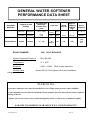
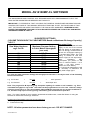
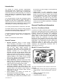
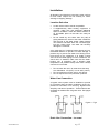
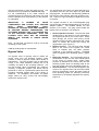
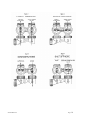
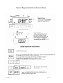
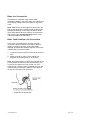
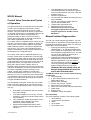
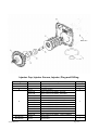
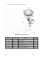
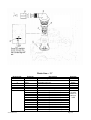
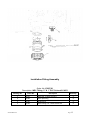
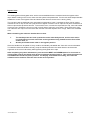
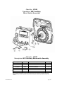
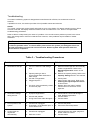
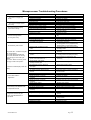
WATER SOFTENER
WITH MICROPROCESSOR
INSTALLATION & OPERATING
INSTRUCTIONS
Model :
Serial No :
AS14100MP-CL
………………………..
Manufacturer and Supplier of
FILTRATION & WATER TREATMENT PRODUCTS
for commercial, industrial and residential application
Telephone: (07) 3219 2233
Email: [email protected]
AS14100MP-CL
Facsimile: (07) 3219 2266
Website: www.ibcwater.com.au
Page 1
GENERAL WATER SOFTENER
PERFORMANCE DATA SHEET
Recommended
Capacity & Salt
Dosage
Automatic
Model No.
AS14100MP-CL
Maximum
Service Flow
Rate
Pipe Size
Resin
Volume
Approx.
Shipping
Weight
(kg)
Space
Required
Minimum
Maximum
Cont. / Peak
Inlet
Outlet
Drain
gram/kg
gram/kg
Flow
LPM
mm
mm
Litres
Per Kg
metres
3500/6
7000/24
71 / 100
25
BSP-F
20
100
233
1.00
0.70
2.2
WxDxH
BRINE CHAMBER:
350L POLY MOULDED
System Operating Pressure:
330- 690 kPa
Temperature:
4o x 43oC
Electrical:
240V—16VAC 50Hz 3 watts maximum
Control Valve:
fittings.
Series WS1-E1 with bypass valve and installation
WARNING
A pressure reduction valve must be installed in areas of high water pressure (above 690kPa)
A water hammer arrestor must be installed if water hammer prevails, between the softener and the
closing off device.
Caution: Do not use where water is microbiologically unsafe or with water of unknown quality.
FAILURE TO OBSERVE WARNINGS WILL VOID WARRANTY
AS14100MP-CL
Page 2
AS14100MP-CL
Page 3
BASIC INSTALLATION
OF
IBC TWO TANK WATER SOFTENER SYSTEM
FITTED WITH MODEL WS1 VALVE/EI CONTROL
Check the equipment upon arrival for damage or shortages and report same to our Office or Agent before
starting.
Position the Softener and Brine Tank on a firm foundation, preferably concrete, with sufficient space for
operation and maintenance.
STEP 1
Make sure the softener tank is empty and clean.
STEP 2
Install the distributor tube in the softener tank, check the height in relation to top of softener
tank. (Approximately 12mm above the top of the tank).
STEP 3
Place a plastic cap over the end of the distributor pipe. A clean rag or plastic bag will suffice if
plastic cap is not available - NO media must enter distributor pipe.
STEP 4
Place a wide mouth funnel in the mouth of the tank and FIRST load the No.6 gravel (16kg.)
and then the 100 litres of softening resin and fill with water to within 50mm of the top.
Note :- The resin must not be allowed to be spilled on the floor as it is very slippery and
dangerous to walk on.
STEP 5
Clean top of neck and threads of all traces of gravel and resin. Remove the plastic cap fitted
in Step 3 taking care not to raise the distributor pipe. NEVER shorten the length of the
distributor pipe.
STEP 6
Unpack control valve, check that tank ‘O’ ring is in place. Fit the top strainer into the
bottom of the valve if not already fitted. The strainer has a bayonet style connection end.
Assemble the control valve to softener tank, and screw down hand tight.
STEP 7
Connect inlet, outlet pipes and drain line to control valve as per Instruction Booklet.
STEP 8
Remove lid from brine tank, connect brine tube from elbow assembly on control valve, to
brine riser tube in brine tank. Then connect brine overflow drain line to waste trap.
STEP 9
Load the 2 bags of No.4 Gravel (40kg.) evenly around the bottom of the brine tank and level
off, making sure the slotted distributor pipe in the brine tank bottom is covered by the gravel.
STEP 10
Load ten bags of 25kg high purity water softener salt into brine tank and replace lid.
STEP 11
Refer to Instruction booklet for start up procedure (placing conditioner into Service")
NOTE: The INLET PIPE connection is on the right hand side as viewed
from the front of the valve. The top strainer must be fitted into underneath
the valve.
Table 3
MODEL
AS14100MP-CL
AS14100MP-CL
RESIN LITRES
BRINE TANK - SALT
LOADING KG
100
250
Page 4
WS1-MP VALVE
Top Strainer
The softener is shipped unassembled and it is necessary to assemble the
Strainer into the Valve (by Matching Up the Locating Lugs and Twisting To
Lock) prior to the loading of the resin and screwing on the valve to the
tank. Note Never Shorten the Riser Pipe installed inside the tank.
AS14100MP-CL
Page 5
WATER HARDNESS TEST METHOD
1.
Water to be tested should be taken from a tap after the water softener
2.
Measure 10ml of water into plastic bottle supplied (approximately 1/3 full)
3.
Add one Yes/No tablet to sample water, replace cap and shake until tablet
has completely dissolved.
(NOTE: do not handle Yes/No tablet with fingers)
4.
The final colour to be obtained for soft water is green. (Note: The shade of
green may vary.) If the colour turns red, the water is above 20 mg/l hardness,
therefore another regeneration is recommended. However if the raw water
is very high in hardness it may not be possible to achieve a reduction in
hardness below 20mg/l but the softener is still working correctly.
Consult IBC Water for further clarification.
5.
6.
Rinse plastic bottle after each test has been completed.
7.
When used as above, the tablets change the colour from green to red at a
hardness of approximately 20ppm based on a sample volume of 10mls.
Other hardness test kits are available for more accurate testing eg.
Hardness Tablets
Directions:
Take a 50ml sample of water in a screw capped bottle. Add one (1)
tablet to sample, shake or crush to disintegrate. Repeat until last trace
of reddish tinge disappears. The final colour is usually blue but with
some water a greyish coloured end point is obtained.
Using 50ml sample Hardness ppm = (number of tablets x 40) - 20
LR (BW) Tablets
Directions:
Take a 100ml sample of water in a screw capped bottle. Add one (1)
tablet to sample, shake or crush to disintegrate. Repeat until last trace
of reddish tinge disappears. The final colour is usually blue but with
some water a greyish coloured end point is obtained.
Using 100ml sample Hardness ppm = (number tablets x 2) – 1
Contact IBC Water if further details are required.
AS14100MP-CL
Page 6
MODEL AS14100MP-CL SOFTENER
THE MICROPROCESSOR CONTROL WILL REQUIRE BASIC DATA PROGRAMMING TO SUIT THE
RAW WATER HARDNESS AND DESIRED UNIT CAPACITY
IMPORTANT: IT IS ESSENTIAL THAT YOU READ THE GENERAL CONDITIONER INFORMATION AND
CONTROL SETTINGS OF THIS MANUAL BEFORE ATTEMPTING TO SET THE FUNCTIONS OF THIS
UNIT. THE DEALER OR AGENT CAN SUPPLY THE RAW WATER HARDNESS. HOWEVER DO NOT
EXCEED THE MAXIMUM THROUGH PUT IN CUBIC METERS BASED ON THE ACTUAL RAW WATER
HARDNESS FIGURE IN TABLE 2.
SUGGESTED SETTINGS
(VOLUME THROUGHPUT IN CUBIC METRES Based on Maximum Exchange Capacity )
TABLE 2
Important Note:
To provide uninterrupted soft water
Raw Water Hardness
Maximum Program Setting
supply to the end of the service
mg/L CaCO3
In Cubic Metres throughput
and just before a regeneration is
(see note)
due it is strongly recommended to
60
80
100
120
140
160
180
200
250
115.50
87.50
70.00
57.50
50.00
43.50
38.50
35.00
28.00
de-rate the throughput setting by
the average daily usage. Eg. If the
setting is elected at 70.0 then
deduct a figure of one days usage.
(Note:
Estimated
daily
consumption per person is 300
litres or 0.3Cubic Metres :- for 3
people = 0.9 cubic metres :deduct One Cubic Metre.)
For Commercial applications it will
be necessary to determine the
daily water usage figure.
For other raw water hardness multiply the throughput at 100 hard i.e.70.0 by the ratio of 100 divided by
the desired hardness.
e.g. for 75 hard
=
70x 100
=
93.3 input 92.5
75
e.g. for 150 hard
=
70x 100
=
46.66 input 46.5
150
3
Note: The program for M input will only accept the inputting of a whole or half a number. e.g. If the
3
calculated throughput is say 9.75m then what can be programmed in is 9.5 or 10.0. However, always
select the lower figure i.e. 9.5 in this example. Above 50M³ the program will only accept increments in
2.5 , therefore only input a lower figure eg. Calculation gives 93.3 therefore input 92.5.
Note :- The chart is based on low to medium total dissolved solids water ,consult IBC Water for using the
softener for waters above 250 mg/L hardness.
Programming Parameters to be input at commissioning:
1. Throughput in cubic metres from Table 2.
2. Current time of day.
NOTE: All other parameters have been factory pre-set – DO NOT CHANGE.
AS14100MP-CL
Page 7
CUSTOMER/ INSTALLER
PROGRAMING INSTRUCTIONS
The WS1-E1 has been factory programmed with the majority of the commands and parameters installed. It is
necessary on commissioning of the softener to program in the M3 throughput” and if desired another time of
day when regeneration is to proceed or accept the factory default of 2am and to set up the clock to register
the current time of day. The transformer plugs into the adaptor mounted on the back face of the front panel of
the valve
The procedure is as follows :
Plug in the transformer into the mains and turn on – valve will sequence to the service position.
Step 1I – To enter installer display press the NEXT
and ▲ buttons simultaneously for 5 seconds and
release. Display flashes.
Step 2I – Using the
keys input desired
volumetric throughput capacity (table 2 ) in cubic
meters ( Adjustable from 0.5 - 250.0). It is suggested
the value entered be equal to the actual volumetric
capacity minus a 1 day’s estimated water usage.
Press NEXT to go to Step 3I
Step 3I – Use or buttons to Set to “OFF”
Press NEXT to go to Step 4I.
.
Step 4I – Use or buttons to set the time of regen
‘hour’. Press NEXT to go to Step 5I. If the factory
default of 2am is to be changed.
Step 5I – Use or buttons to set the time of regen
‘minutes’. Press NEXT to exit installer display.
Setting Current Time of Day
Exit back to display screen which would normally show
3
‘remaining M ’. Note: When in the program mode. Step 1 to
5. If it is desired to go back one program step press ‘regen’
button to return back.
Push NEXT button until TIME of day screen is
displayed ie bar appears under TIME function . Press
and hold the OR arrow until a arrow appears
against SET and release the button and the hour
display flashes and then set the correct hour. Then
press the NEXT button. The minutes will flash. Press
the OR arrow until the correct minutes is
displayed. Note only press one ▲OR ▼button NOT
both together.
Press the NEXT button to return to the display screens.
If the NEXT button is not pressed hours or minutes will
flash for five minutes before returning to display
screen.
Then using the NEXT button select which screen you
wished displayed. Recommended to leave on
‘remaining-M3’.
AS14100MP-CL
Page 8
Power outage
When electric power is interrupted the microprocessor will hold all relevant information in memory except for
the current time of day.
Current time of day
When power is restored the display will show zeros and will again register when the current time of day is
reset. If power is lost during a regeneration cycle the valve will remain operational in the current cycle and will
recommence electrically in that cycle when power is restored.
In long power outages it is advisable to check that the system is not in a regeneration cycle that could be
discharging water to drain and in this instance it would be advisable to place the valve in bypass mode until
power is restored.
General
Note: When changing valve operational cycles the valve control will emit a number of whirring sounds.
Note :- The valve cannot be positioned into the regeneration mode without ELECTRIC Power.
Note:- It is very important that on commissioning the tank and valve be completely vented of air .
AS14100MP-CL
Page 9
MODEL AS14100MP WATER SOFTENER
WITH CONTROL VALVE SERIES MODEL WS1EI
AS14100MP-CL
Page 10
GENERAL WS1 CONTROL VALVE SPECIFICATONS
Inlet/Outlet Fittings
25mm BSP “F” PVC elbows
Cycles
Valve Material
Regeneration
5
Noryl (1) or equivalent
Down flow
FLOW RATES
Service @15psi/1 bar drop (includes bypass & meter)
102 lpm
Backwash @25psi/1.7 bar drop (includes bypass)
102 lpm
OPERATING PRESSURE
Minimum/Maximum
330-600 kpa (48-100 psi)
METER
Accuracy
Flow Rate Range
+- 5%
0.95-102lpm
Volume Range
Totaliser
0.500-250.0 m3
0.001-9,999,000 m3
DIMENSIONS & WEIGHT
Distributor Pilot
Drain Line
1.050” OD Pipe (3/4” NPS)
3/4” (20mm) Hose Tail
Brine Line
Mounting Base
Height from Top of Tank
3/8” OD Poly Tube
2 /12” – 8 NPSM
7 3/8” (187mm)
Weight
Distributor Pilot
ELECTRICAL SPECIFICATIONS
4.5lbs (2kg)
12mm Above Tank Top
AC Adaptor
Supply Voltage
Supply Frequency
Output Voltage
230V AC
50 Hz
12—16 V AC
Output Current
500 mA
CYCLES OF OPERATION
Range -times minutes
Factory Set
Backwash 1st (upflow)
Regenerate draw/slow rinse (downflow)
Backwash 2nd (upflow)
1-20
1-99
1-20 or OFF
12
85
OFF
Fast Rinse (downflow)
Regenerant Refill (in service with treated water)
Service (downflow)
1-20 or OFF
0.1 – 99.9
10
40.5
(Noryl is a trademark of General Electric)
AS14100MP-CL
Page 11
Table of Contents
Specifications …………………………………………………………… 10
Introduction ……………………………………………………………… 12
Special Features
General Conditioner Information …………………………………….. 12-13
How Your Conditioner Works
Model E1 Control Front Panel
Installation – important installation details….…………………….. 14-15
Bypass Valve …………………………………………………………… 15-16
Screen Display Information and Programming Instructions ….. 17-19
General Display Status
Regeneration and Error Display Status
Basic Button Function
Water Conditioner Regeneration ………………………………….…. 20
Automatic Regeneration
Manual Regeneration
Care of Your Water Conditioner ……………………………………… 20
General
Cleaning the Injector/Injector Screen
Maintaining the Drain Line
Brine Line and Brine Tank Overflow Connection ……..………….. 21
Placing Softener into Operation .………………………………….…. 22
Valve Manual …………………………………………………………….. 23-25
Replacement Parts …………………………………………………….... 26-38
Service Instructions………………………………………………………39-46
Troubleshooting ………………………………………………….……… 47-49
Alarms
Troubleshooting Procedures
Glossary of Terms …………………………………………………….…. 50
Safety
Caution
Warning
The plug-in transformer for this
equipment is rated for indoor use
only.
Never attempt o work on this control while
standing in or near water without
disconnecting electrical power to the
control.
AS14100MP-CL
Page 12
Introduction
The Model E1 Control provides sophisticated,
demand-based water conditioning by incorporating a
microprocessor and a water meter to electronically
monitor the amount of water used daily. The control is
factory programmed to regenerate when the volume
throughput setting is reached at a present delayed
time of 2am.
It is recommended to de-rate the throughput setting
by one days general usage to ensure soft water is
available on the day of regeneration. However in
instances where this is not desired the control can be
reprogrammed so that a regeneration can be initiated
immediately on reaching the throughput setting.
•
be lost due to a power outage, so reprogramming
is not necessary.
Guest Cycle. An extra regeneration can be
achieved at any time by pressing the REGEN
button on the front panel. It takes a few minutes
for the regeneration to start. The unit completes
the regeneration in about two hours. This feature
is beneficial when you expect to use more than
the normal amount of water; for example, guest
visits or an extra heavy laundry day. The manual
can be set for immediate regeneration of delayed
regeneration at 2am.
General Conditioner Information
The control provides efficient, trouble free, soft water.
The Series WS1-EI valve combines design simplicity
with glass reinforced NORYL* plastic construction to
provide an uncommonly reliable appliance.
If maintenance becomes necessary, the Model WS1EI water Conditioner System has the capability for
quick repairs.
NORYL is a trademark of GE Plastics.
Special Features
•
•
•
•
•
Memory Retention. During a power outage,
critical operating information in the control's
memory is stored in a special electronic device
called a NOVARAM. This information includes the
time of day, water usage amounts, all
programming data. When power is restored, the
information is returned to the microprocessor and
operation resumes as if an outage never
occurred. The time of day will be late by the
length of the power outage. Because most power
outages are less than one minute in duration, it
may be months or years before the time display
requires resetting. If an outage of one or more
hours occurs, the time of day should be reset but
no other reprogramming is necessary.
Design Reliability. Solid-state electronics assure
many years of trouble-free performance. The
metering system has only one moving part; a
rotating turbine that measures water usage.
Time and Capacity Display. During normal
conditioning operation, the correct time of day
and capacity can be accessed on the display. The
capacity value is the number of cubic metres of
water that the unit can condition before another
regeneration is needed.
Flow indicator. The display can access the
actual flow rate through the system.
Throughput and Capacity Setting. Once the
capacity setting is entered, the information cannot
AS14100MP-CL
How Your Conditioner Works
In general, your water conditioner works in the following manner. Hard water flows into the conditioner and
through the resin bed where calcium and magnesium
hardness minerals are exchange. The conditioned
water flows out of the resin bed into your plumbing
system. After a certain amount of hard water has
passed through the conditioner, the resin cannot
remove any more minerals. This resin state is called
exhaustion and indicates that the resin needs to be
regenerated. The regeneration process restores the
conditioner's ability to soften water. The control
monitors the amount of water that flows through the
conditioner and automatically calculates when to
regenerate the resin bed.
Model E1 Control Front Panel
Figure 1
The main components of the model E1 Control front
panel are:
• Main Display Screen with Cycle Time Remaining
• Display screen – set as ‘remaining M3’ or time of
day
• Display can indicate Rate of Flow
• Four-Digit Display
• Programming Push Buttons
Page 13
•
REGEN Push Button
•
Five-cycle operation provides for downflow conditioned water, upflow backwash, downflow brining
and slow rinse, downflow fast rinse, and refill of
the brine tank. Optional second backwash
available.
•
System operation cannot get out of phase or
sequence. The control always returns to a fixed
conditioned water position after regeneration.
•
Bypass untreated water is automatically available
during regeneration.
AS14100MP-CL
Page 14
Installation
All plumbing and electrical connections must conform
to local codes. Inspect the unit carefully for carrier
shortage or shipping damage.
Location Selection
•
•
•
Locate unit as close to a drain as possible
If supplementary water treating equipment is
required, make sure that adequate additional
space is available. Locate the cabinet softener in
an accessible place so that salt can easily be
added.
Do not install any unit closer than 3m (10ft) of
piping between the outlet of the water conditioner
and the inlet of the water heater. Water heaters
can transmit heat back down the cold water pipe
into the control valve. Hot water can severely
damage the controller.
A 3m total pipe run (including bends, elbows etc) is a
reasonable distance to prevent hot water damage. A
positive way to prevent hot water from flowing from a
heat source to the conditioner is to install a check
valve in the soft water piping from the conditioner. If a
check valve is installed, make sure that the waterheating unit is equipped with a properly rated
temperature and pressure safety relief valve. Always
conform to local codes.
•
•
•
Do not locate the unit in an area where the temp
ever falls below 1ºC (34ºF) or over 49ºC (120ºF).
Do not install the unit near acid or acid fumes.
Do not expose the unit to petroleum products.
Water Line Connection
A bypass valve system must be installed to provide
for occasions when the water conditioner must is bypassed for hard water or for servicing. Bypass offers
simplicity and ease of operation. These softeners are
equipped as standard with a bypass valve. See pages
14 and15
Figure 3 – Typical
Drain Line Connection – to sewer
AS14100MP-CL
Page 15
The ideal location for the unit is above and not more
than 6.1m (20ft) from the drain. For such installations,
using the appropriate adaptor fitting (supplied),
connect 20mm (3/4”) plastic tubing to the drain line
connection located on the top of the valve.
Important Installation Details
The control valve, fittings and/or bypass are designed
to accommodate minor plumbing misalignments but
are not designed to support the weight of the system
or the plumbing.
Do no use Vaseline, oils, other hydrocarbon lubricants
or spray silicone anywhere. A silicone lubricant may
be used on black o-rings but is not necessary. Avoid
any type of lubricants, including silicone, on the
clear lip seals.
Figure 5 - Air Gap Installation
If the unit is located more than 6.1m (20ft) from the
drain, use 25mm tubing for runs up to 12.0m. You
may elevate the line up to 1.8m providing the run
does not exceed 4.5m and the water pressure at the
conditioner is not less than 280kPa (40psi.) You may
elevate an additional 500mm for each additional
70kPa. (10psi) of water pressure.
When the drain line is elevated and empties into a
drain which is below the level of the control valve,
form a 170mm (7 inch ) loop at the drain end of the
line so that the bottom of the loop is level with the
drain line connection. This provides an adequate
siphon trap.
If the drain empties into an overhead sewer line, a
sink-type trap must be used.
Caution
Never connect the drain line into a drain,
sewer line or trap. Always allow an air gap
between the drain line and the wastewater
to prevent the possibility of sewage being
back-siphoned into the conditioner.
Not In Bypass
In Bypass
The nuts and caps are designed to be unscrewed or
tightened by hand or with the special plastic wrench.
Do not use a pipe wrench to tighten or loosen nuts or
caps. Do not place a screwdriver in the slots on caps
and/or tap with a hammer.
Do not use pipe dope or other sealant on threads.
Use teflon tape on threaded inlet, outlet and drain
fittings.Teflon tape is not necessary on the nut
connection or caps because of o-ring seals.
After completing any valve maintenance involving
the drive assembly of the drive camp assembly
and pistons, press and hold NEXT and REGEN
buttons for 3 seconds or unplug power source
jack from the printed circuit board (black wire)
and plug back in. This resets the electronics and
establishes the service piston position. The display
should flash all wording, then flash the software
version and then reset the valve to the service
position.
All plumbing should be done in accordance with local
plumbing codes. The pipe size for the drain line
should be a minimum of 20mm.
Solder joints near the drain must be done prior to
connecting the drain line flow control fitting. Leave at
least 150mm (6”) between the drain line control fitting
and solder joints when soldering pipes that are
connected on the drain line control fitting. Failure to
do this could cause interior damage to the drain line
flow control fitting.
When assembling the installation fitting package (inlet
and outlet), connect the fitting to the plumbing system
first and then attach the nut, split ring and o-ring.
Heat from soldering or solvent cements may damage
the nut, split ring and o-ring. Solder joints should be
cool and solvent cements should be set before
installing the nut, split ring or o-ring. Avoid getting
primer and solvent cement on any part of the o-rings,
bypass valve or control valve.
Position the softener within 1 ½ metres of a 10 amp
GPO. The transformer is connected into the plug
socket on the back of the valve control panel. Do not
AS14100MP-CL
Page 16
drop the transformer or have the cable too taut. The
transformer is only suitable for internal use only.
For full understanding of the water softener we
recommend that the instruction manual be fully read
before installation and commissioning of the softener
by undertaken.
The bypass body and rotors are glass filled Noryl (or
equivalent) and the nuts and caps are glass filled
polypropylene. All seals are self-lubricating EPDM to
help prevent valve seizing after long periods of nonuse. Internal o-rings can easily be replaced if service
is required.
IMPORTANT:
A
NUMBER
OF
VALVE
COMPONENTS ARE LOCKED INTO POSITION
WITH
EASILY
REMOVABLE
CLIPS.
ENSURE ALL LOCKING CLIPS ARE CORRECTLY
IN POSITION BEFORE PRESSURISING THE
SOFTENER. ENSURE THAT IT IS POINTED OUT
TO ALL RELEVANT PERSONNEL THAT THE
LOCKING CLIPS MUST NOT BE REMOVED
WHILST THE SYSTEM IS UNDER WATER
PRESSURE.
The bypass consists of two interchangeable plug
valves that are operated independently by red arrowshaped handles.
The handles identify the flow
direction of the water. The plug valves enable the
bypass valve to operate in four positions.
Note: All electrical connections must be connected
according to local codes.
Install grounding strap on metal plates.
Bypass Valve
The bypass valve is typically used to isolate the
control valve from the plumbing system’s water
pressure in order to perform control valve repairs or
maintenance. The WS1 bypass valve is particularly
unique in the water treatment industry due to its
versatility and state of the art design features. The
full flow bypass valve incorporates four positions,
including a diagnostic position that allows service
personnel to work on a pressurised system while still
providing untreated bypass water to the facility or
residence. Its completely non-metallic, all plastic
design allows for easy access and serviceability
without the need for tools.
AS14100MP-CL
1. Normal Operation Position: The inlet and outlet
handles point in the direction of flow indicated by
the engraved arrows on the control valve. Water
flows through the control valve during normal
operation and this position also allows the control
valve to isolate the media bed during the
regeneration cycle. (Figure 1)
2. Bypass Position: The inlet and outlet handles
point to the centre of the bypass, the control
valve is isolated from the water pressure
contained in the plumbing system. Untreated
water is supplied to the plumbing system. (Figure
2)
3. Diagnostic Position: The inlet handle points in
the direction of flow and the outlet handle points
to the centre of bypass valve, system water
pressure is allowed to the control valve and the
plumbing system while not allowing water to exit
from the control valve to the plumbing.(Figure 3)
4. Shut Off Position: The inlet handle points to the
centre of the bypass valve and the outlet handle
points in the direction of flow, the water is shut off
to the plumbing system (i.e. plumbing connection
somewhere in the building bypasses the system).
(Figure 4)
Page 17
AS14100MP-CL
Page 18
WS1EI
Screen Display Information
And
Programming Instructions
AS14100MP-CL
Page 19
General Operation
General Display
When the system is operating, one of four displays
may be shown. Pressing NEXT will alternate between
the displays shown below.
User 1
Shows volume remaining to regeneration.
User 3
Displays flow rate M3/hour.
User 4
Displays total flow in cubic metres since last reset.
Can be used to estimate average daily usage.
PRESS DOWN ARROW FOR 3 SECONDS TO
RESENT TO ZERO.
User 5
Shows current time.
Setting Time of Day
Push NEXT button until time of day screen is
displayed. Press and hold the
or arrow until the
correct hour is displayed.
Then press NEXT button.
The minutes will flash.
Press the
or
arrow until correct minute is
displayed.
Press the NEXT button to return to the display
screens. If the NEXT button is not pressed hours or
minutes will flash for five minutes before returning to
display screens.
AS14100MP-CL
Page 20
General Regeneration Error Screens Status
AS14100MP-CL
Page 21
Water Conditioner Regeneration
Your water conditioner regenerates for one of two
reasons:
• The control determines that the conditioner has
reached the throughput setting volume capacity.
• The REGEN button was pressed.
The injector is the component, which creates the
vacuum necessary to draw the brine into the water
conditioner. Clean the injector and the injector screen
once a year in order to maintain proper water
conditioning. Some locations may require more
frequent injector and screen servicing.
Complete the following steps to clean the injector and
the injector screen:
1. Unplug the wall mount transformer.
Automatic Regeneration
2. Shut off the water supply or put the bypass valve
into the bypass position.
The control makes regeneration decisions based on
the amount of water that has flowed through the
conditioner and the programmed throughput figure.
3. Depressurise the pipework by opening a tap in
the service line.
The factory setting for Time of Regeneration is 2:00
AM. You can change this time. Refer to the
Customer/Installer Programming Instructions
section in this manual for additional information.
4. Unscrew the injector cap (large top slotted cap)
and lift off. Loosen cap with special plastic wrench
or pliers if necessary. Attached to the injector cap
is a screen. Remove the screen and clean if
fouled.
Manual Regeneration
To force the control to perform a regeneration, press
the REGEN push button. This button is located on the
front of the control. When you press the REGEN
button, the control performs a full regeneration of the
conditioner. You can use this feature if you need a
large amount of conditioned water but the capacity
remaining is low.
Note: If you press this button once and release
immediately. The regeneration will occur at the
delayed time setting i.e. 2am. If an immediate
regeneration is required then hold in the button for 3
seconds.
The injector can be pried out with a small
screwdriver. The injector consists of a throat and
nozzle. Chemically clean the injector with
vinegar. The holes can be blown out with air.
Both pieces have small diameter holes that
control the flow rates of water to insure that the
proper concentration of regenerant is used.
Sharp objects, which can score the plastic,
should not be used to clean the injector. Scoring
the injector or increasing the diameter of the hole
could change the operating parameters of the
injector. Push the injector firmly in place, replace
the screen and hand tighten the injector cap.
5. Close off the tap in service line and reposition
bypass valve back into service position.
Care of Your Water Conditioner
Maintaining the Drain Line
General
The drain line discharges and brine during the
regeneration cycle. Typically, the line drains into a
sewer connection. The installer should plumb the
drain line according to local codes, leaving a one or
two inch air gap between the end of the drain line and
the drain opening.
Check the salt level in the salt storage tank regularly.
Always maintain the salt level above the water level
for a consistent salt dosage and proper water
conditioner operation. Don't allow the conditioner to
run out of salt before refilling. When refilled, the salt
storage tank contains enough salt to support
numerous resin bed regenerations. It is recommended
to utilise a high grade water softener salt like IBC
premium grade. Do not use a fine grade of salt. Have
the salt storage tank serviced once a year to remove
accumulated sediment that may impede brine draw.
Be sure that the drain line remains unrestricted so the
regeneration water and brine can flow freely to the
drain. Do not set objects on the drain line that could
crimp the line and restrict flow.
Cleaning the Injector/Injector Screen
AS14100MP-CL
Page 22
Brine Line Connection
The brine line comprises a pick up air check
assembly installed in the brine wall in the cabinet and
connected by tubing to the brine elbow on top of the
valve.
Note: Make sure that all fittings and connections are
tight so that premature checking does not take place.
Premature checking occurs when the ball in the air
check seals before all brine is drawn out of the brine
tank. Refer to the Troubleshooting section in this
manual for additional information.
Brine Tank Overflow Line Connection
In the event of a malfunction, the tank overflow
connection directs overflow to the drain instead of
spilling on the floor where it could cause water
damage. Complete the following steps to connect the
overflow fitting to the brine tank:
1. Locate the fitting overflow on the side of the brine
tank.
2. Attach a length of 1/2in (1.3cm) tubing (not
supplied) to the fitting and run to the drain.
Note: Do not elevate the overflow line higher than 3in
(7.6cm) below the bottom of the overflow fitting. Do
not tie into the drain line of the control unit. The
overflow line must be a direct, separate line from the
overflow fitting to the drain, sewer or tube. Allow an
air gap as in the drain line connection.
Overflow Line Connection
AS14100MP-CL
Page 23
12. Allow the salt to dissolve in the brine
compartment for at least 30 minutes.
Placing Softener into Operation
13. It is recommended to give a new softener a
complete regeneration before placing fully into
service.
Initial Start-Up
14. Press and hold the “regen” button until the display
starts to blink and go into the backwash mode.
1. Mains water turned off to unit or bypass valve in
shut off mode.
2. Connect transformer to power point and turn on.
3. Program controller as per “Customer/Install
Programming Instructions”.
4. Press the “Regen” button in and hold for 3 to 5
seconds.
5. The softener will advance to the backwash
position and start counting down.
6. Slowly open the inlet valve or the bypass valve
into the “Diagnostic Mode” approximately one
quarter of t a turn and allow the mineral tank to
slowly fill up with water.
Caution
If the water supply valve is opened too rapidly
or too far, resin may be lost. In the BACKWASH
position, you should hear air escaping slowly
from the drain line.
7. When all the air is purged from the tank (water
begins to flow steadily from the drain), slowly
open the main supply valve all the way. Allow the
water to run into the drain until the water appears
clear. Turn off the water supply and wait for a few
minutes to allow all trapped air to escape from the
tank. Then open the inlet valve/bypass inlet
slowly and allow the backwash to time down.
15. Allow to count down to the draw mode. When the
valve is in this mode and counting down check to
see that brine is being drawn out of the cabinet
into the valve. The brine draw is very slow and all
brine will be drawn out until the air check on the
brine riser tube shuts off. The system will then
remain in the draw cycle to slowly rinse (And
regenerate) the brine through the resin.
16. Allow the system to complete a full regeneration
and return to the service position. This will take a
few hours.
17. When the unit has returned to the service position
with the normal display then open the bypass
valve outlet valve slowly to enable water to enter
the treated water line ensure that the bypass
valve is correctly in “Normal Operation” position.
18. Open a tap in the treated water and allow to run
to drain for a few minutes. Then check the
harness of the water with the supplied test kit.
If not soft allow to run to drain for 5 minutes and
recheck the hardness.
Refer to “troubleshooting” section if the water is
still hard.
8. Press the “regen” button and allow valve to
position into the draw cycle. Once the valve is
positioned and display registering a time down
then again press “regen” and allow to advance to
rinse – Once again when display starts to count
down press “regen” button.
9. Display will register a small backwash time and
then move down to fill.
10. Allow to fill the brine compartment. Check that
water is slowly flowing into the brine well by lifting
up the brine well cap.
11. Allow to time out and note water level in brine
compartment. The compartment should have
been prior filled with salt. The valve will then go
back into the service mode.
AS14100MP-CL
Page 24
•
WS1EI Manual
•
•
Control Valve Function and Cycles
of Operation
•
1
This glass filled Noryl (or equivalent) fully automatic
control valve is designed as the primary control
center to direct and regulate all cycles of a water
softener. The control valve can be set to regenerate
on demand (consumption of a predetermined amount
of water) and/or as a time clock (passage of a
particular number of days). The control valve is
factory set to regenerate on demand consumption
with a delay regeneration set for 2am.
The control valve is compatible with a variety of resin
cleaners. The control valve is capable of routing the
flow of water in the necessary paths to regenerate
water treatment systems. The injector regulates the
flow of brine. The control valve regulates the flow
rates for backwashing, rinsing and the replenishing of
treated water into a regenerant tank.
The control valve uses no traditional fasteners (e.g.
screws); instead clips, threaded caps, nuts and snap
type latches are used. Caps and nuts only need to be
firmly hand tightened because radial seals are used.
Tools required to service the valve include one small
blade screw driver, one large blade screw driver,
pliers and a pair of hands. A plastic wrench is
available which eliminates the need for screwdrivers
and pliers. Disassembly for servicing takes much less
time than comparable products currently on the
market. Control valve installation is made easy
1
because the distributor tube can be cut 12.7mm ( /2“)
1
above to 12.7 mm ( /2“) below the top of tank thread.
The distributor tube is held in place by an o-ring seal
and the control valve also has a bayonet lock feature
for upper distributor baskets.
The AC adapter power pack comes with a 2.0 meter
power cord and is designed for use with the control
valve. The AC adapter power pack is for dry location
use only.
•
•
•
•
Solid state microprocessor with easy access
front panel settings.
Front panel display for time of day, volume
remaining, current flow rate and total volume
used (Totalizer).
Four methods to initiate regeneration; meter
immediate, meter delayed, time clock
delayed or pressure differential.
Optional double backwash feature offers
optimum regeneration cleaning ability and
efficiency.
AS14100MP-CL
•
•
•
Fully adjustable 6-cycle control delivers
controlled backwash, downflow brining/slow
rinse, second backwash, fast rinse, refill and
downflow service.
Downflow regeneration.
12-volt output AC Adapter provides safe and
easy installation.
Control valve design provides optimum
service and backwash rates.
Treated water regenerant refill.
Reliable and proven DC Drive.
General Factory set up is for M³
throughput regeneration with 2 AM
delayed regeneration and No second
Backwash.
Manual Initiated Regeneration
The user can initiate manual regeneration. The user
has the option to request the manual regeneration at
the delayed regeneration time of 2am or to have the
regeneration occur immediately:
1. Pressing and releasing immediately the
REGEN button. “ƒ” will flash towards regen
on the display and regeneration will occur at
2am the delayed regeneration time. The user
can cancel the request by pressing and
releasing the REGEN button.
2. Pressing and holding the REGEN button for
approximately 3 seconds will immediately
start the regeneration. The user cannot
cancel this request, except by resetting the
control by pressing NEXT and REGEN
buttons simultaneously for 3 seconds.
However this may totally clear all
the pre-programmed in functions
and is not recommended.
The WS1EI control valve consist of the following
components:
1. Drive Assembly
2. 2. Drive Cap Assembly, Main Piston and
Regenerant Piston.
3. Spacer Stack Assembly.
4. Injector Cap, Screen, Injector.\
5. Refill Flow Control Assembly.
6. Drain Line Flow Control and Fitting Assembly.
7. Water Meter.
8. Bypass Valve.
9. Installation Fitting Assemblies.
Drive Assembly
The drive assembly consists of the following parts:
• Drive Bracket.
• Printed Circuit (PC) Board.
• Motor
• Drive Gears
• Drive Gear Cover
Page 25
The drive bracket holds the PC board, the motor, the
drive gears and the drive gear cover in place.
The PC board receives and retains information,
displays the information, determines when to
regenerate and initiates regeneration. The display
show different types of information in the initial
system set up, installer display settings, diagnostics or
user display settings.
The PC board powers the motor. The PC board’s twoprong jack connects wires to the direct current (DC)
motor. The motor is held in place on the drive bracket
by a spring-loaded clip and a small bulge in the
plastic, which fits in one of the slots on the motor
housing. The motor turns drive gears that drive the
piston to cycle positions for backwashing,
regeneration, rinsing, refill or service. The motor is
fully reversible (turns both ways) and changes
direction of rotation to change the direction of piston
motion. The motor is easily replaced if necessary.
There are three drive gears held in place by the drive
gear cover. All three drive gears are the same size. A
reflective coating is applied to the gears. As the
centre drive gear turns a light shines on the coating
and a light sensing diode determines if a light pulse
was returned. The PC board counts the pulses and
determines when to stop driving the motor.
Drive Cap Assembly, Main Piston
and Regenerant Piston
The drive gears turn the main gear of the drive cap
assembly, which moves the piston. The screw-driven,
horizontally moving piston stops at specific positions
to direct the flow of water to backwash, regenerate,
rinse or refill. The PC board determines the position
of the piston by counting pulses produced when the
piston is moved. An optical sensor looking at one of
the reduction drive gears generates these pulses.
Each cycle position is defined by a number of pulses.
The counter is zeroed each time the valve goes to the
service position. The PC board finds the service
position by noting the increase in current delivered to
the motor when the mechanical stop at the service
position is reached. This method of controlling the
piston position allows for greater flexibility and
requires no switches or cams (U.S. Patent 6,444,127).
Spacer Stack Assembly
The spacer stack assembly provides the necessary
flow passage for water during the different cycles.
The all-plastic spacer stack assembly (U.S. Patent
6402944) is a one-piece design which allows the
stack to be removed using your fingers.
The exterior of the stack is sealed against the body
bore with self lubricating EPDM o-rings, while the
AS14100MP-CL
interior surface is sealed against the piston using
slippery self cleaning silicone lip seals. The lip seals
are clear in colour and have a special slippery coating
so that the piston does not need to be lubricated.
Injector Cap, Screen, Injector Plug
and Injector
The screen, injector and/or injector plug(s) are
installed under the injector cap in an easy to access
location on top of the valve. The injector cap contains
four slots so no water accumulates in the cap. The
injector cap is designed to be hand tightened.
Under the injector cap there is an easy to clean
removable screen to prevent fouling of the injector.
There are two holes under the injector cap labelled
“DN” and “UP”. The injector is in the “DN” hole and
the “Up” hole is plugged.
The injector lets water pass through the pathway. The
self-priming injector increases the velocity of the
water, creating a zone of negative pressure that
draws in the concentrated liquid regenerant sodium
chloride (brine). The regenerant blends with the
stream of water which passes through the media to
regenerate the resin bed.
The injector provides a consistent regenerant/water
mixture ratio over the entire operating pressure range
of the control valve. The injector provides good
performance in a variety of applications. The injector
fitted has been used to suit a wide range of operating
pressures. But requires a minimum of 330 kpa to
function correctly.
Injector Order Information
Injector order
Injector
Typical tank
number
colour
Diameter*
V3010-1B
Brown
7”
V3010-1D
Red
9”
*V3010-1E/F
White/Blue
10”
V3010-1G
Yellow
12”
V3010-1I
Orange
13”
V3010-1K
Light Green
14”
* May vary with Tank Resin Volume Check with
Factory
Refill Flow Control Assembly or
Refill Port Plug
The refill flow control assembly consists of a refill flow
elbow, refill flow control retainer assembly, refill flow
control, polytube insert and nut assembly. The refill
flow control retainer fits in the refill elbow. The refill
Page 26
flow control retainer houses the refill flow control
which controls the flow rate when the regenerant tank
is being refilled. The refill flow control is a flexible
washer-like part with a small orifice and a precision
moulded contour that delivers a steady 1.91pm (0.5
gpm) regenerant tank refill rate at varying inlet
pressures. Refill is accomplished with treated water.
The turbine is accurate to within ± 5% over a wide
operating flow rate range 0.95 lpm (0.25 gpm) up to
control valve maximums and has a very low pressure
drop. Water used for regeneration is not metered. If
the control valve is in regeneration mode (e.g. a
backwash cycle) and there is a water demand, that
water usage is not metered.
The refill flow control assembly is installed in an easy
to access refill elbow located on top of the control
valve. The refill flow control assembly is installed in
an easy to access refill elbow located on top of the
control valve. The refill flow control assembly is
attached to the control valve with a locking clip. The
locking clip allows the elbow to rotate 270 degrees so
the outlet can be orientated towards the regenerant
tank.
When facing the front of the control valve, the water
meter is positioned on the left-hand side of the control
valve. Allow sufficient clearance to clean and repair
the water meter without disconnecting the plumbing or
disassembling any other parts of the control valve.
The control valve has a standard refill elbow to which
a 3/8” flexible tube can be connected. The supplied
Tube Insert must be used.
Drain Line Flow Control and Fitting
Assembly
The drain line flow control assembly includes a drain
line flow control and a fitting. The drain line flow
control allows proper media bed expansion by
regulating the flow rate to the drain. The drain line
flow control is a flexible washer-like part with an
orifice and a precision moulded contour. The flow
rates are within ± 10% over the pressure range of 1.4
bar (20 psi) to 8.6 bar (125 psi).
The drain line flow control and fitting are located on
top of the control valve and replaceable without the
use of special tools.
The drain line flow control can be installed in the
standard ¾” drain line elbow, which accommodates
5/8” polytube or pipe 20mm threaded drain line
connections. The optional nut and polytube insert for
the drain line elbow is designed for use with flexible
polytube only. The drain line elbow can be rotated
180 degrees so the outlet can be orientated to the
nearest drain. This softener is supplied with a 20mm
push on hose elbow.
Water Meter Hall Effect Explanation
3
Some semiconductor materials exhibit a phenomenon in
the presence of a magnetic field that is adaptable to
sensing devices. When a current is passed through one
pair of wires attached to a semiconductor will develop a
voltage proportional to the magnetic field present and the
current in the other pair of wires. Holding the exciting
current constant and moving a permanent magnet near the
semiconductor, produces a voltage output proportional to
the movement of the magnet. Hall effect devices provide a
high speed response, excellent temperature stability, and
no physical contact.
Installation Fitting Assemblies
The installation fittings are used to connect the
bypass to the plumbing system. Standard fittings
supplied are a 25mm BSP Female PVC elbow
assembly.
Both elbow fittings have a unique drill out feature to
allow a ¼” NPT connection to the inlet and/or outlet
which can be used for a RO feed, test ports, pressure
tap ports, etc.
Water Meter or Meter Plug
The water meter is installed on the outlet side of the
control valve. The water meter uses a turbine to
measure cubic metres of treated water. The turbine
rotates with the flow of water and reports its rate of
3
rotation through Hall effect circuitry to the printed
circuit (PC) board. This rotation permits the PC board
to record the total volume of treated water and the
flow rate. The small centrally located magnet is
shielded from water, which substantially reduces ironfouling problems with the turbine.
AS14100MP-CL
Page 27
SPARE PARTS
AND
SERVICING INSTRUCTIONS
AS14100MP-CL
Page 28
WS1E1 Front Cover and Drive Assembly
Drawing No.
Order No.
Description
Quantity
1
V3175EI-01
WS1EI Front Cover Assembly
1
2
V3107-01
WS1 Motor
1
3
V3106-01
WS1 Drive Bracket & Spring Clip
1
4
V3408E1
WS1.5 PC Board EI
1
5
V3110
WS1 Drive Gear 12x36
3
6
V3109
WS1 Drive Gear Cover
1
V3002EI
WS1EI Drive ASY
*
V3186-01
WS1 AC ADAPTER CORD ONLY
1
Not Shown
* Drawing number parts 2 through 6 may be purchased as a complete assembly, part V3002EI.
AS14100MP-CL
Page 29
WE1EI Drive Cap Assembly, Downflow Piston, Regenerant Piston and
Spacer Stack Assembly
Drawing No.
Order No.
Description
Quantity
1
V3005
WS1Spacer Stack Assembly
1
2
V3004
Drive Cap ASY
1
3
V3178
WS1 Drive Back Plate
1
4
V3011*
WS1 Piston Downflow ASY
1
5
V3174
WS1 Regenerant Piston
1
6
V3135
O-ring 228
1
7
V3180
O-ring 337
1
8
V3105
O-ring 215 (Distributor Tube)
1
Not Shown
V3001
WS1 Body ASY Downflow
1
*V3011 is labelled with DN.
AS14100MP-CL
Page 30
Injector Cap, Injector Screen, Injector, Plug and O-Ring
Drawing No.
1
2
3
5
Not Shown
Not Shown
AS14100MP-CL
Order No.
V3176
V3152
V3177
V3010-1A
V3010-1B
V3010-1C
V3010-1D
V3010-1E
V3010-1F
V3010-1G
V3010-1H
V3010-1I
V3010-1J
V3010-1K
V3170
V3171
Description
Injector Cap
O-ring 135
Injector Screen
WS1 INJECTOR ASSY - BLACK
WS1 INJECTOR ASSY - BROWN
WS1 INJECTOR ASSY - VIOLET
WS1 INJECTOR ASSY - RED
WS1 INJECTOR ASSY - WHITE
WS1 INJECTOR ASSY - BLUE
WS1 INJECTOR ASSY - YELLOW
WS1 INJECTOR ASSY - GREEN
WS1 INJECTOR ASSY - ORANGE
WS1 INJECTOR ASSY - LIGHT BLUE
WS1 INJECTOR ASSY - LIGHT GREEN
O-ring 011
O-ring 013
Quantity
1
1
1
1
*
*
Page 31
•
The injector plug has one 011 (lower) and 013 (upper) o-ring.
Refill Flow Control Assembly
Drawing No.
Order No.
Description
2
H4615
Elbow Locking Clip
1
3
JCP-P-6
Polytube insert 3/8”
1
4
JCPG-6PBLK
Nut 3/8”
1
5
H4613
Elbow Cap 3/8”
1
6
V3163
O-ring 019
1
7
V3165-01*
WS1 RFC Retainer ASY
1
8
V3182
WSC RFC
1
Not Shown
H4650
Elbow ½” with nut and insert
* Assembly includes V3182 WS1 RFC.
AS14100MP-CL
Quantity
Option
Page 32
Drain Line – ¾”
Drawing No.
1
2
3
4
5
6
7
AS14100MP-CL
Order No.
H4615
PKP10TS8BULK
V3192
V3158-01
V3163
V3159-01
V3162-007
V3162-010
V3162-013
V3162-017
V3162-022
V3162-027
V3162-032
V3162-042
V3162-053
V3162-065
V3162-075
V3162-090
Description
Elbow Locking Clip
Polytube insert 5/8
WS1 Nut ¾ Drain Elbow
WS1 Drain Elbow ¾ Male
O-ring 019
WS1 DLFC Retainer ASy
WS1 DLFC 0.7 gpm for ¾ 2.6 lpm
WS1 DLFC 1.0 gpm for ¾ 3.8 lpm
WS1 DLFC 1.3 gpm for ¾ 4.9 lpm
WS1 DLFC 1.7 gpm for ¾ 6.5 lpm
WS1 DLFC 2.2 gpm for ¾ 8.3 lpm
WS1 DLFC 2.7 gpm for ¾ 10.2 lpm
WS1 DLFC 3.2 gpm for ¾ 12.1 lpm
WS1 DLFC 4.2 gpm for ¾ 16 lpm
WS1 DLFC 5.3 gpm for ¾ 20 lpm
WS1 DLFC 6.5 gpm for ¾ 24.7 lpm
WS1 DLFC 7.5 gpm for ¾ 28.5 lpm
WS1 DLFC 9.0 gpm for ¾ 34.2 lpm
Quantity
1
Option
Option
1
1
1
One DLFC
must be
used if ¾
fitting is
used
Page 33
V3162-100
WS1 DLFC 10.0 gpm for ¾ 38 lpm
Softeners are supplied with a 20mm Push ON Hose Connection as standard the illustrated Nut and 5/8”
Tube Insert are only supplied as an option.
Water Meter and meter Plug
Drawing No.
Order No.
Description
Quantity
1
V3151
WS1 Nut 1: QC
1
2
V3003*
WS1 Meter ASY
1
3
V3118-01
WS1 Turbine ASY
1
4
V3105
O-ring 215
1
* Order number V3003 includes V3118-01 WS1 Turbine Assy and V3105 O-ring 215.
AS14100MP-CL
Page 34
Installation Fitting Assembly
Order No: V3007-01
Description: WS1 Fitting ¾” & 1” PVC Solvent 90۫ ASY
Drawing No.
AS14100MP-CL
Order No.
Description
Quantity
1
V3151
WS1 Nut 1” Quick Connect
2
2
V3150
WS1 Split Ring
2
3
V3105
O-Ring 215
2
4
V3189
WS1 Fitting ¾ & 1 PVC Solvent 90
2
Page 35
Bypass Valve
Drawing No.
AS14100MP-CL
Order No.
Description
Quantity
1
V3151
WS1 Nut 1” Quick Connect
2
2
V3150
WS1 Split Ring
2
3
V3105
O-ring 215
2
4
V3145
WS1 Bypass 1” Rotor
2
5
V3146
WS1 Bypass Cap
2
6
V3147
WS1 Bypass Handle
2
7
V3148
WS1 Bypass Rotor Seal Retainer
2
8
V3152
O-ring 135
2
9
V3155
O-ring 112
2
Page 36
10
V3156
O-ring 214
2
Flow Diagrams – Service and Backwash
flow diagram…service
AS14100MP-CL
Page 37
flow diagram…backwash
Flow Diagram – Downflow
AS14100MP-CL
Page 38
flow diagram…downflow brine
Flow Diagrams – Rinse and Fill
AS14100MP-CL
Page 39
flow diagram…rinse
flow diagram…fill
WS1 Wrench
(Order No. V3193-01)
AS14100MP-CL
Page 40
Although no tools are necessary to assemble or disassemble the valve, the WS1 wrench (shown in various
positions on the valve) may be purchased to aid in assembly or disassembly.
Service Instructions
AS14100MP-CL
Page 41
Drive Assembly
Remove the valve cover to access the drive assembly.
Disconnect the power source plug (black wire) from the PC board prior to disconnecting the motor or water
meter plugs from the PC board. The power source plug connects to the four-pin jack. The motor plug connects
to the two-pin jack on the left-hand side of the PC board. The water meter plug (gray wire) connects to the
three-pin jack on the far right-hand side of the PC board.
The PC board can be removed separately from the drive bracket but it is not recommended. Do not attempt to
remove the display panel from the PC board. Handle the board by the edges. To remove the PC board from
the drive bracket, unplug the power, water meter and motor plugs from the PC board. Lift the middle latch
along the top of the drive bracket while pulling outward on the top of the PC board. The drive bracket has two
plastic pins that fit into the holes on the lower edge of the PC board. Once the PC board is tilted about 45°
from the drive bracket it can be lifted off of these pins. To reinstall the PC board, position the lower edge of the
PC board so that the holes in the PC board line up with the plastic pins. Push the top of the PC board towards
the valve until it snaps under the middle latch, weave the power and water meter wires into the holders and
reconnect the motor, water meter and power plugs.
The drive bracket must be removed to access the drive cap assembly and pistons or the drive gear cover. It is
not necessary to remove the PC board from the drive bracket to remove the drive bracket. To remove the
drive bracket start by removing the plugs for the power source and the water meter. Un weave the wires from
the side holders. Two tabs on the top of the drive back plate hold the drive bracket in place. Simultaneously lift
the two tabs and gently ease the top of the drive bracket forward. The lower edge of the drive bracket has two
notches that rest on the drive back plate. Lift up and outward on the drive bracket to disengage the notches.
To reassemble, seat the bottom of the drive bracket so the notches are engaged at the bottom of the drive
back plate. Push the top of the drive bracket toward the two latches. The drive bracket may have to be lifted
slightly to let the threaded piston rod pass through the hole in the drive bracket. Maintain a slight engaging
force on top of the drive bracket while deflecting the bracket slightly to the left by pressing on the side of the
upper right corner. This helps the drive gears mesh with the drive cap assembly. The drive bracket is properly
seated when it snaps under the latches on the drive back plate. If resistance is felt before latching, then
notches are not fully engaged, the piston rod is not in hold, the wires are jammed between the drive bracket
and drive back plate, or the gear is not engaging the drive cap assembly.
To inspect the drive gears, the drive gear cover needs to be removed. Before trying to remove the gear cover,
the drive bracket must be removed from the drive back plate. (Refer to the instructions above regarding
removing the drive bracket from the drive back plate. The drive gear cover can be removed from the drive
bracket without removing the motor or the PC board.) The drive gear cover is held in place on the drive
bracket by three clips. The largest of the three clips is always orientated to the bottom of the drive bracket.
With the PC board facing up, push in and down on the large clip on the drive gear cover. Handle the cover and
the gears carefully so that the gears do not fall off of the pegs in the cover.
Replace broken or damaged drive gears. Do not lubricate any of the gears. Avoid getting any foreign matter
on the reflective coating because dirt or oils may interfere with pulse counting.
The drive gear cover only fits on one way, with the large clip orientated towards the bottom. If all three clips
are outside of the gear shroud on the drive bracket the drive gear cover slips easily into place.
The drive bracket does not need to be removed from the drive plate if the motor needs to be removed. To
remove the motor, disconnect the power and motor plugs from the jacks on the PC board. Move the spring clip
loop to the right and hold. Rotate the motor at least a ¼ turn in either direction so the wires are vertical (up &
down) before gently pulling on the wire connectors to remove the motor. Pulling directly on the wires without
rotating the motor may break the wires off the motor.
Replace the motor if necessary. Do not lubricate the motor or the gears. To reinstall the motor, move the
spring clip loop to the right and hold. Gently turn the motor while inserting so that the gear on the motor
meshes with the gears under the drive gear cover. Release the spring clip loop and continue to rotate the
motor until the wires are horizontal and the motor housing engages the small plastic bulge inside the drive
AS14100MP-CL
Page 42
bracket motor retainer. Reconnect the motor plug to the two-pronged jack on the lower left hand side of the PC
board. If the motor will not easily engage with the drive gears when reinstalling, lift and slightly rotate the motor
before reinserting. Reconnect the power plug.
Replace the valve cover. After completing any valve maintenance, press and hold NEXT and REGEN buttons
for 3 seconds or unplug power source jack (black wire) at the circuit board and plug back in. This resets the
electronics and establishes the service piston position. The display should flash all wording, then flash the soft
ware version and then rest the valve to the service position.
Drive Cap Assembly, Main Piston and Regenerant Piston
The drive assembly must be removed to access the drive cap assembly. The drive cap assembly must be
removed to access the piston(s). The drive cap assembly is threaded into the control valve body and seals
with an o-ring. To remove the drive cap assembly use the special plastic wrench or insert a ¼” to ½” flat blade
screwdriver into one of the slots around the top 2” of the drive cap assembly so it engages the notches
moulded into the drive back plate around the top 2” of the piston cavity. The notches are visible through the
holes. Lever the screwdriver so the drive cap assembly turns counter clockwise. Once loosened, unscrew the
drive cap assembly by hand and pull straight out.
The drive cap assembly contains the drive cap, the main drive gear, drive cap spline, piston rod and various other parts that should not be
dissembled in the field. The only replaceable part on the drive cap assembly is the o-ring. Attached to the drive cap assembly is the main piston
(downflow) and if a regenerant is used, a regenerant piston.
The regenerant piston (the small diameter one behind the main piston) is removed from the main piston by
pressing sideways and unsnapping it from its latch. Chemically clean in vinegar, or replace the regenerant
piston if needed. To remove the main downflow or upflow piston fully extend the piston rod and then unsnap
AS14100MP-CL
Page 43
the main piston from its latch by pressing on the side with the number. Chemically clean in vinegar, or replace
the main piston.
Reattach the main piston to the drive cap assembly. Reattach the regenerant piston to the main piston. Do not
lubricate the piston rod, main piston or regenerant piston. Lubricant will adversely affect the clear lip seals.
Reinsert the drive cap assembly and piston into the spacer stack assembly and hand tighten the drive cap
assembly. Continue to tighten the drive cap assembly using the optional wrench or a screwdriver as a ratchet
until the black o-ring on the spacer stack assembly is no longer visible through the drain port. Excessive force
can break the notches moulded into the drive back plate. Make certain that the main drive gear still turns
freely. The exact position of the piston is not important as long as the main drive gear turns freely.
Reattach the drive assembly to the control valve and connect all plugs. After completing any valve
maintenance, press and hold NEXT and REGEN buttons for 3 seconds or unplug power source jack (black
wire) and plug back in. This resets the electronics and establishes the service piston position. The display
should flash all wording, then flash the software version and then reset the valve to the service position.
Spacer Stack Assembly
To access the spacer stack assembly remove the drive assembly, drive cap assembly and piston. The spacer
stack assembly can be removed easily without tools by using thumb and forefinger. Inspect the black o-rings
and clear lip seals for wear or damage. Replace the entire stack if necessary. Do not disassemble the stack.
The spacer stack assembly may be chemically cleaned with vinegar or wiped with a soft cloth.
The spacer stack assembly can be pushed in to the control valve body bore by hand. Since the spacer stack
assembly can be compressed it is easier to use a blunt object (15.9mm (5/8”) to 28.6 mm (1-1/8”) in diameter)
to push the centre of the assembly into the control valve body. The assembly is properly seated when at least
four threads are exposed (approximately 15.89 mm (5/8”). Do not force the spacer stack assembly in. The
control valve body bore interior can be lubricated with silicone to allow for easy insertion of the entire stack. Do
not use silicone or any other type of lubricant on the clear lip seals or the piston.
Reattach the drive cap assembly and piston(s) and the drive assembly.
IMPORTANT NOTE:After completing any valve maintenance, press and hold NEXT and REGEN buttons for 3 seconds or
unplug power source jack (black wire) at the circuit board and plug back in. This resets the electronics
and establishes the service piston position. The display should flash all wording, then flash the
software version and then reset the valve to the service position.
Injector Cap, Screen, Injector Plug and Injector
Unscrew the injector cap and lift off. Loosen cap with special wrench or pliers if necessary. Attached to the
injector cap is a screen. Remove the screen and clean if fouled.
The injector can be pried out with a small screwdriver. The injector consists of a throat and a nozzle.
Chemically clean the injector with vinegar. The holes can be blown out with air. Both pieces have small
diameter holes that control the flow rates of water to insure that the proper concentration of regenerant is used.
Sharp objects, which can score the plastic, should not be used to clean the injector. Scoring the injector or
increasing the diameter of the hole could change the operating parameters of the injector. Push the injector
firmly in place, replace the screen and hand tighten the injector cap.
Two holes are label “DN” and “UP”. Check for compliance. See Compliance table
AS14100MP-CL
Page 44
Compliance Table
Application
WS1EI Downflow Softener or
Regenerating Filter
Injector and/or
Plug(s)
Injector in “DN” hole.
Main
Piston
Regenerant
Piston
Stack
Body
V3011
V3174
V3005
V3001
Refill Flow Control Assembly or Refill Port Plug
To clean or replace the refill flow control, pull out the elbow-locking clip and then pull straight up on the elbow.
Replace the elbow locking clip in the slot so that it is not misplaced. Twist to remove the white flow control
retainer. The flow control can be removed by prying upward through the side slots of the retainer with a small
flat blade screwdriver.
Chemically clean the flow control or the white flow control retainer using vinegar. Do not use a wire brush. If
necessary, replace the flow control, o-ring on the flow control retainer, or the o-ring on the elbow.
Reseat the flow control so the rounded end is visible in the flow control. Reseat the white flow control retainer
by pushing the retainer into the elbow until the o-ring seats. Remove locking clip, push down on elbow to
reseat and insert locking clip.
Do not use Vaseline, oils, or other unacceptable lubricants on o-rings. A silicone lubricant may be used on the
o-ring on the elbow or the white retainer.
Water Meter or Meter Plug
The water meter assembly is connected to the PC board by a cable. If the entire water meter assembly is to be
replaced, remove the control valve cover and disconnect the power source and water meter plugs from the PC
board. Unlatch the drive assembly and lean it forward. Unthread the water meter wire from the side of the
drive assembly and through the drive back plate. To reinstall, rethread the water meter wire through the drive
back plate and the side of the drive assembly. Reattach the drive assembly and the water meter and power
plugs.
If no water meter wire is visible, then a plug is installed, not a water meter.
The water meter cable does not need to be removed from the PC board if the water meter is only being
inspected and cleaned. To remove the water meter assembly, unscrew the meter cap on the left side of the
control valve. Pliers may be used to unscrew the nut if necessary.
With the nut removed, a slot at the top of the water meter is visible. Twist a flat blade screwdriver in the slot
between the control valve body and the meter. When the meter is part way out it is easy to remove the water
meter from the housing. Once the water meter is removed from the control valve body, gently pull forward on
the turbine to remove it from the shaft.
Do not use a wire brush to clean the turbine. Wipe with a clean cloth or chemically clean in vinegar. The
turbine can be immersed in the vinegar. Do not immerse electronics. If the turbine is scored or damaged or
the bearings on the turbine are worn, replace the turbine.
Do not lubricate the turbine shaft. The turbine shaft bearings are pre-lubricated. Do not use Vaseline, oils, or
other unacceptable lubricants on the o-ring. A silicone lubricant may be used on the black o-ring.
Snap the turbine on the shaft and reinsert the water meter into the side slot. Hand tighten the nut. Do not use a
pipe wrench to tighten nut.
AS14100MP-CL
Page 45
Bypass Valve
The working parts of the bypass valve are the rotor assemblies that are contained under the bypass valve
caps. Before working on the rotors, make sure the system is depressurized. Turn the red arrow shaped handles
towards the centre of the bypass valve and back several times to ensure rotor is turning freely.
The nuts and caps are designed to be unscrewed or tightened by hand. if necessary a pliers can be used to
unscrew the nut or cap. Do not use a pipe wrench to tighten or loosen nuts or caps. Do not place screwdriver in
slots on caps and/or tap with a hammer. To access the rotor, unscrew the cap and lift the cap, rotor and handle
out as one unit. Twisting the unit as you pull it out will help to remove it more easily. There are three o-rings:
one under the rotor cap, one on the rotor stem and the rotor seal. Replace worn o-rings. Clean rotor. Reinstall
rotor.
When reinstalling the red arrow handles be sure that:
1.
2.
The handle pointer are lined up with the control valve body arrows, and the rotor seal oring and retainer on both rotors face to the right when being viewed from the front of the
control valve; or
Arrows point toward each other in the bypass position.
Since the handles can be pulled off, they could be accidentally reinstalled 180° from their correct orientation.
To install the red arrow handles correctly, keep the handles pointed in the same direction as the arrows
engraved on the control valve body while tightening the bypass valve caps.
After completing any valve maintenance, press and hold NEXT and REGEN buttons for 3 seconds or
unplug power source jack (black wire) at the circuit board and plug back in. This resets the electronics
and establishes the service piston position. The display should flash all wording, then flash the
software version and then reset the valve to the service position.
AS14100MP-CL
Page 46
Order No.: V3009
Description: WS1 Auxiliary
Micro Switch Assembly
iliary
Micro Switch Assembly
Order No.: V3009
Description: WS1 Auxiliary Microswitch Assembly
Drawing No.
Order No.
Description
Quantity
1
V3301
WS1 MICROSWITCH
1
2
V3302
WS1 MOLEX CONNECTOR
1
Not Shown
V3303
WS1 MOLEX TERMINAL
3
3
V3304
WS1 SCREWS 4/40 X 5/8
2
4
V3305
WS1 RETAINING RING SS ¼
1
5
V3306
WS1 WASHER ID 0.257 OD 0.640
1
Slip the washer and retaining ring on to the end of the piston rod. Attach the microswitch to the drive
bracket using the screws. Attach the connector to the microswitch. Attach the terminals to wires and
connect.
AS14100MP-CL
Page 47
INJECTOR PERFORMANCE CURVES
AS14100MP-CL
Page 48
AS14100MP-CL
Page 49
Troubleshooting
Your water conditioning system is designed and manufactured for efficient, low maintenance service.
However,
if problems do occur, this section provides a list of possible causes and solutions.
Alarms
The control continuously monitors itself and sends an error to the display if it detects something wrong. When
the error is sensed, the display shows the letters Err with a number from 1 to 4. Refer to microprocessor
troubleshooting procedures.
Refer to table 3 to help identify the cause of a problem. You can solve some problems yourself, such as low
salt in the storage tank or a blown household fuse. However, some problems require installer or dealer
assistance.
Caution
Service procedures that require the water pressure to be removed from the system are marked with
a ! after the possible cause. To remove water pressure from the system, put the bypass valve into
the shut off position and open the service line valve. Restore system water pressure when the
service work is completed.
Table 3 – Troubleshooting Procedures
Problem
Cause
Solution
1. Hard water at the tap.
a. Low or no salt in the salt storage
tank.
a. Refill the salt storage tank and manually
initiate a regeneration. Refer to the
Manual Regeneration section in this
manual.
b. Reduce the capacity setting. Refer to the
Capacity Setting section in this manual.
b. Capacity setting to low to
accommodate water hardness or
water usage.
c. Unit did not regenerate.
d. Plugged injector. !
e. Air check valve prematurely closed,
in brine riser pipe.
2. Hard water leakage
during service.
a. Improper Regeneration.
b. Internal seal problem.
c. O-ring around riser tube damaged. !
c. Check power.
d. Clean injector and screen. Refer to the
Cleaning the Injector/Injector Screen
in this manual.
e. Replace brine riser pipe if needed.
Check brine line connection for air
tightness.
a. Check that the correct salt dosage is
used. Repeat regeneration.
b. Contact dealer.
c. Contact dealer.
3. Loss of power to the
system.
a. Transformer unplugged.
b. Fuse blown, circuit breaker open, or
circuit switched off.
a. Connect the power.
b. Correct the electrical problem.
4. Control does not
regenerate
AS14100MP-CL
automatically.
a. Transformer unplugged.
a. Plug transformer into outlet; plug transformer cable into
control.
Page
50
b. Contact dealer.
b. Defective control.
AS14100MP-CL
Page 51
Table 3 – Troubleshooting Procedures
6. Control does not draw
brine.
- cont…
a. Low water pressure
b. Restricted drain line.
c. Injector or injector screen plugged. !
d. Injector defective. !
e. Valve general malfunction
f. Air check prematurely closed in
brine tank
a. Increase water pressure.
b. Remove restriction.
c. Clean injector and screen, Refer to the
Cleaning the Injector/Injector Screen
section in this manual.
d. Replace injector. Contact dealer.
e. Contact dealer
f. Replace or repair air check if needed.
Check brine line connections.
7. Intermittent or irregular
brine draw.
a. Low water pressure.
b. Defective injector. !
a. Increase water pressure.
b. Replace both injector and injector cap.
Contact dealer.
8. Brine tank overflow.
a. Air leak in brine line to air check.
a. Check all connections in brine line for
leaks.
b. Contact dealer.
b. Refill program setting incorrect.
9. System using more or
less salt than estimated.
a. Inaccurate program setting of brine
refill.
b. Air check system incorrect.
a. Contact dealer.
c.
c.
Defective brine refill operation
control
b. Contact dealer.
Contact dealer.
10. Control backwashes at
excessively low or high
rate.
a. Incorrect backwash controller.
b. Foreign matter affecting controller
operation. !
a. Contact dealer.
b. Remove backwash controller. Clean &
replace.
11. Flowing or dripping water
at drain line after
regeneration.
a. Internal valve malfunction.
a. Contact dealer.
AS14100MP-CL
Page 52
Microprocessor Troubleshooting Procedures
Problem
1. Timer does not display time
of day.
2.
Timer does not display correct
time of day.
3. No softening/filtering display
when water is flowing.
Possible Cause
Solution
a. AC Adapter unplugged
b. No electric power at outlet
c. Defective AC adapter
d. Defective PC board
a. Switched outlet
b. Power Outage
c. Defective PC board
a. Bypass valve in bypass position
b. Meter connection disconnected
c. Restricted/stalled meter turbine
a. Connect power
b. Repair outlet or use working outlet
c. Replace AC adapter
d. Replace PC board
a. Use uninterrupted outlet
b. Reset time of day
c. Replace PC board
a. Put bypass valve in service position
b. Connect meter to PC board
c. Remove meter and check for rotation
or foreign material
d. Replace meter
e. Replace PC board
a. Reset control valve to correct time of
day
b. Reset to correct time of day
c. Reset regeneration time
d. Check control valve set-up procedure
regeneration time option.
a. Press NEXT and REGEN for 3 seconds
or unplug power source jack (black wire)
and plug back in to reset control valve.
b. Check piston and spacer stack assembly
for foreign matter
d. Defective meter
e. Defective PC board
a. power outages
4. Control valve regenerates
at wrong time of day.
b. Time of day not set correctly
c. Time of regeneration incorrect
d. Control valve set at “on O”
(immediate regeneration)
a. Control valve has just been serviced
5. Err followed by code number
b. Foreign matter is lodged in control
valve
Error Code 1001 – Unable to recognize
start of regeneration
Error Code 1002-Unexpected stall
Error Code 1003-Motor ran too long,
timed out trying to reach next cycle
position
Error 1004 – Motor ran too long, timed
out trying to reach home position
If other Error Codes display contact the
factory.
6. Control valve stalled in
regeneration
7. Control valve does not regenerate
automatically when REGEN button
is depressed and held
8. Control valve does not
Regenerate automatically but
does when REGEN button is
depressed
c. high drive forces on piston
c. Replace piston(s) & spacer stack
assembly
d. Control valve piston not in home
position
c. Press NEXT and RGEN for 3 seconds
or unplug power source jack (black wire)
and plug back in to reset control valve
e. Check motor and wiring. Replace motor if
necessary
e. Motor not inserted fully to engage
pinion, motor wires broken or
disconnected, motor failure
f. Drive gear label dirty or damaged,
missing or broken gear
g. Drive bracket incorrectly aligned to
back plate
g. Reseat drive bracket properly
h. PC board is damaged or defective
i. PC board incorrectly aligned to drive
bracket.
h. Replace PC board
i. Ensure PC board is correctly snapped on
to drive bracket.
a. Motor not operating
b. No electric power at outlet
c. Broken drive gear or drive cap
assembly
d. Defective PC board
e. Broken drive gear or drive cap
assembly
f. Broken piston retainer
g. Broken main or regenerant piston
a. AC adapter unplugged
b. No electric power at outlet
c. Broken drive gear or drive cap
assembly
d. Defective PC board
a. Bypass valve in bypass position
a. Replace motor
b. Repair outlet or use working outlet
c. Replace AC adapter
b. Meter connection disconnected
c. Restricted/stalled meter turbine
d. Defective meter
e. Defective PC board
f. Set-up error
AS14100MP-CL
f. Replace or clean drive gear
d. Replace PC board
e. Replace drive gear or drive cap assembly
f. Replace piston retainer
g. Replace main or regenerant piston
a. Connect AC adapter
b. Repair outlet or use working outlet
c. Replace drive gear or drive cap assembly
d. Replace PC board
a. Put bypass valve in normal operation
position.
b. Connect meter to PC board
c. Remove meter and check for rotation or
foreign matter
d. Replace meter
e. Replace PC board
f. Check control valve set-up procedure
Page 53
9. Time of day flashes on and off
a. Power has been out more than two hours,
the AC adapter was unplugged and then
plugged back into the wall outlet, the AC
adapter plug was unplugged and then
plugged back into the board or the NEXT
and REGEN buttons were pressed to reset
the valve.
a. Reset the time of day
Glossary of Terms
Alarms
Hardness
Display errors alert you to operating conditions
requiring attention. The display shows the type of
error. Refer to the Alarms section in this manual
for additional information.
A common quality of water containing dissolved
calcium, magnesium and other elements. Water
hardness is usually expressed milligrams per litre
as calcium carbonate equivalent.
Backwash
Manual Regeneration
An upward flow of water, which expands the resin
bed to remove foreign particles.
Forces the control to regenerate by pressing the
REGEN button.
Brine
Regeneration
The salt solution which regenerates the
conditioner’s resin bed.
Includes the backwash, brine draw, and fresh water
rinse steps necessary to prepare the resin bed for
conditioning after exhaustion.
Brine Draw
Regeneration Indicator
The process of drawing the brine solution from the
salt storage tank into the resin tank.
Fast Rinse (Purge)
A flow of water through the resin bed which propels
any remaining brine solution out of the resin tank to
the drain.
AS14100MP-CL
The display arrow which indicates the regeneration
cycle status.
Resin Bed
The supply of synthetic organic exchange material
used in water conditioners. This material is subject
to degradation and will need to be renewed. Resin
replacement normally varies between 3 to 7 years.
Page 54