1
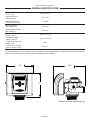
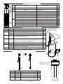
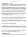
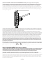
INSTALLATION, OPERATING AND SERVICE MANUAL ELECTRONIC WATER SOFTENER WITH THE X-FACTOR CONTROL VALVE PROGRAMMED FOR PRE-FILL BRINING OPTION 7-LXC-50 7-LXC-75 7-LXC-100 7-LX-75 7-LX-100 7-LX-150 7-LX-200 7-LX-300 Congratulations on purchasing your new Lancaster Water Softener. This unit is designed to give you many years of trouble free service. When installed in accordance with the following instructions and if given reasonable care, clear-soft water will be the result. For servicing and future inspection purposes, please file this booklet with your important documents. In the event that you need assistance for servicing your water softener, please first contact the professional contractor who installed the system. PAGE 1 TABLE OF CONTENTS Job Specifications ......................................................................................................................... Pre-Installation Review . ................................................................................................................ General Installation and Service Warnings ................................................................................... Bypass Valve Operation ................................................................................................................ Installation Instructions, Diagrams ................................................................................................ Placing Softener into Service ........................................................................................................ General Operation ......................................................................................................................... Set Time of Day ............................................................................................................................. Adjust Hardness, Days Between Regenerations or Time of Regeneration . ................................. Low Battery.................................................................................................................................... Contact Screen Programming ....................................................................................................... Specifications ................................................................................................................................ Parts Diagrams . ............................................................................................................................ Service Instructions ....................................................................................................................... Troubleshooting . ........................................................................................................................... JOB SPECIFICATIONS MODEL NO. INSTALLATION DATE SERIAL NUMBER INSTALLER NAME PHONE ADDRESS WATER TEST AT TIME OF INSTALLATION Hardness CaCo3 (gpg) Other: Iron (ppm) pH SIZING INFORMATION All Water is Softened Except: Rear Hose Bib Other Front Hose Bib Kitchen Cold Toilets All Cold The average family uses 50 gallons per person daily for all water uses in the home. Daily Water Usage (Gallons/Person) x Family Size (Number of people in family) = Total Gallons Per Day x Grains Per Gallon of hardness (Note: Add 4 grains per gallon of hardness for each ppm iron for total compensated hardness) = Total Grains per Day PAGE 2 2 3 3 4 5, 6 7 7 8 8, 9 9 9 10-13 14-21 22-24 25-28 PRE-INSTALLATION REVIEW GENERAL INSTALLATION AND SERVICE WARNINGS WATER QUALITY: If sand or sediment is present in the water supply, a sediment filter should be installed ahead of the water softener. Your water softener has been designed to adequately reduce hardness from levels up to 100 grains per gallon. Ferrous bicarbonate iron levels up to 0.5 ppm can also be reduced. This is iron that is dissolved in water and not visible to the eye in a freshly drawn sample. After standing in contact with air, the ferrous iron will become oxidized to the ferric state and start to precipitate as a reddish brown floc. It can be seen and may cause discolored water. Air must not come in contact with water until after it has passed through the water softener. In some cases, additional treatment equipment may be needed to treat water having special characteristics, such as: ferric hydroxide iron, iron bacteria, low pH, tastes and odors, etc. Consult your dealer if you have any questions. This water softener is not to be used for treating water that is microbiologically unsafe or of unknown quality without adequate disinfection before or after treatment. The control valve, fitting and/or bypass are designed to accommodate minor plumbing misalignments but are not designed to support the weight of a system or the plumbing. WATER PRESSURE: A minimum of 20 pounds of water pressure (psi) is required for regeneration. Maximum 100 psi. CAUTION: the softener cannot be subject to a vacuum due to loss of pressure (such as a water main break or submersible well pump check valve failure). WATER TEMPERATURE: The range of water temperature is 35°F to 100°F. DO NOT install any water softener with less than 10 feet of piping between its outlet and the inlet of a water heater. AMBIENT TEMPERATURE: DO NOT locate softener where it or its connections (including the drain and overflow lines) will ever be subject to room temperatures under 33°F. ELECTRICITY: An uninterrupted 120 volt 60Hz source is required. Make sure electrical source is not on a timer or switch. All electrical connections must be connected according to local codes. The plug-in transformer is for dry locations only. Surge protection is recommended with all electrical connections. DRAIN: All plumbing should be done in accordance with local plumbing codes. The distance between the drain and the water softener should be as short as possible. The pipe size for the drain line should be a minimum of 1/2” (inside diameter of pipe). SOFTENING: It is recommended that the softener be installed to soften both the hot and cold water supply. A separate hard water faucet may be plumbed for drinking purposes if desired. Outside faucets should be left on hard water. Do not use Vaseline, oils, other hydrocarbon lubricants or spray silicone anywhere. A silicone lubricant may be used on black o-rings but is not necessary. Avoid any type of lubricants, including silicone, on the clear lip seals. The nuts and caps are designed to be unscrewed or tightened by hand or with the special plastic wrench (V3193). If necessary, pliers can be used to unscrew the nut or cap. Do not use a pipe wrench to tighten or loosen nuts or caps. Do not place a screw driver in the slots on caps and/or tap with a hammer. Do not use pipe dope or other sealants on threads. Use Teflon tape on the threaded inlet, outlet and drain fittings. Teflon tape is not necessary on the nut connection or caps because of o-rings seals. After completing any valve maintenance involving the drive assembly or the drive cap assembly and pistons, unplug power source jack from the printed circuit board (black wire) and plug back in or press and hold NEXT and REGEN buttons for 3 seconds. This resets the electronics and establishes the service piston position. The display should flash the software version and then reset the valve to the service position. Solder joints near the drain must be done prior to connecting the drain line flow control fitting. Leave at least 6” between the drain line control fitting and solder joints when soldering pipes that are connected on the drain line control fitting. Failure to do this could cause interior damage to the drain line flow control fitting. When assembling the installation fitting package (inlet and outlet), connect the fitting to the plumbing system first and then attach the nut, split ring and o-ring. Heat from soldering or solvent cements may damage the nut, split ring or o-ring. Solder joints should be cool and solvent cements should be set before installing the nut, split ring and o-ring. Avoid getting primer and solvent cement on any part of the o-ring, split rings, bypass valve or control valve. Install grounding strap on metal pipes. This water softener is not to be used for treating water that is microbiologically unsafe or of unknown quality without adequate disinfection before or after treatment. BYPASS: A bypass valve (optional accessory) should be installed so that water will be available if it should be necessary to shut off the pressure in order to service the softener. PAGE 3 BYPASS VALVE The bypass valve is typically used to isolate the control valve from the plumbing system’s water pressure in order to perform control valve repairs or maintenance. The X-Factor bypass valve is particularly unique in the water treatment industry due to its versatility and state of the art design features. The 1” full flow bypass valve incorporates four positions, including a diagnostic position that allows service personal to work on a pressurized system while still providing untreated bypassed water to the facility or residence. Its completely non-metallic, all-plastic design allows for easy access and serviceability without the need for tools. The bypass body and rotors are glass filled Noryl® (or equivalent) and the nuts and caps are glass filled polypropylene. All seals are self-lubricating EPDM to help prevent valve seizing after long periods of non-use. Internal o-rings can easily be replaced if service is required. The bypass consists of two interchangeable plug valves that are operated independently by red arrow-shaped handles. The handles identify the flow direction of the water. The plug valves enable the bypass valve to operate in four positions. OPERATION: 1. Normal Operation Position: The inlet and outlet handles point in the direction of flow indicated by the engraved arrows on the control valve. Water flows through the control valve during normal operation and this position also allows the control valve to isolate the media bed during the regeneration cycle. (see figure 1) 2. Bypass Position: The inlet and outlet handles point to the center of the bypass, the control valve is isolated from the water pressure contained in the plumbing system. Untreated water is supplied to the plumbing system. (see figure 2) figure 1 figure 2 figure 3 figure 4 3. Diagnostic Position: The inlet handle points in the direction of flow and the outlet handle points to the center of bypass valve, system water pressure is allowed to the control valve and the plumbing system while not allowing water to exit from the control valve to the plumbing. (see figure 3) 4. Shut Off Position: The inlet handle points to the center of the bypass valve and the outlet handle points in the direction of flow, the water is shut off to the plumbing system. If water is available on the outlet side of the softener it is an indication of water bypass around the system (i.e. a plumbing connection somewhere in the building bypasses the system). (see figure 4) The working parts of the bypass valve are the rotor assemblies that are contained under the bypass valve caps. Before working on the rotors, make sure the system is depressurized. Turn the red arrow shaped handles towards the center of the bypass valve and back several times to ensure rotor is turning freely. The nuts and caps are designed to be unscrewed or tightened by hand. If necessary a pliers or the service spanner wrench can be used to unscrew the nut or cap. Do not use a pipe wrench to tighten or loosen nuts or caps. Do not place screwdriver in slots on caps and/or tap with a hammer. Refer to page 19 for bypass valve parts diagram and service spanner wrench information. To access the rotor, unscrew the cap and lift the cap, rotor and handle out as one unit. Twisting the unit as you pull it out will help to remove it more easily. There are three o-rings: one under the rotor cap, one on the rotor stem and the rotor seal. Replace worn o-rings. Clean rotor. Reinstall rotor. When reinstalling the red arrow handles be sure that: 1. The handle pointers are lined up with the control valve body arrows, and the rotor seal o-ring and retainer on both rotors face to the right when being viewed from the front of the control valve; or 2. Arrows point toward each other in the bypass position. Since the handles can be pulled off, they could be accidentally reinstalled 180° from their correct orientation. To install the red arrow handles correctly, keep the handles pointed in the same direction as the arrows engraved on the control valve body while tightening the bypass valve caps. PAGE 4 INSTALLATION INSTRUCTIONS (All electrical & plumbing should be done in accordance to all local codes) BRINE LINE FITTING CONNECTIONS POLYTUBE DRAIN LINE FITTING CONNECTION USING 5/8" POLY TUBE PAGE 5 W O N y bu to k lic .c o .d o m C w w POLYTUBE ! 6. The brine refill flow control assembly is installed in an easy to access refill elbow located on top of the control valve. The refill flow control assembly is attached to the control valve with a locking clip. The locking clip allows the elbow to rotate 270 degrees so the outlet can be oriented towards the brine tank. 7. Connect the brine line polytubing found with the brine tank to the brine connection on the control valve. The control valve has a standard refill elbow to which a 3/8” flexible tube can be connected, see below. Press the polytube into the brine elbow fitting. Make sure the floor is clean beneath the brine tank and that it is level and smooth. 8. A 1/2” (inside diameter, not provided) gravity drain line should be connected to the overflow fitting on the side of the brine tank. This overflow is in case of a malfunction in the brine shut off. If the unit is installed where water may flow in the event of an overflow and cause water damage, connect a length of flexible tubing and run to a drain below CH A N G F-X(Do the level of the overflow. Enot connect the tubing to PD the drain line on the control valve. Do not run tubing above overflow height at any point.) w 1. Place the softener where you want to install it, making sure it is on a clean, level and firm base. 2. Do all necessary plumbing (inlet to inlet, outlet to outlet, and drain line to drain). The control valve, fittings and/or bypass are designed to accommodate minor plumbing misalignments but are not designed to support the weight of a system or the plumbing. 3. When assembling the installation fitting package (inlet and outlet), connect the fitting to the plumbing system first and then attach the nut, split ring and o-ring. Heat from soldering or solvent cements may damage the nut, split ring or o-ring. Solder joint should be cool and solvent cements should be set before installing the nut, split ring and o-ring. Avoid getting primer and solvent cement on any part of the o-rings, split rings, bypass valve or control valve. 4. A jumper ground wire should be installed between the inlet and outlet pipe whenever the metallic continuity of a water distribution piping system is interrupted. Install grounding strap on metal pipes. 5. The drain connection may be made using either 5/8” polytube (see below) or a 3/4” female adapter. The polytube insert is shipped attached to the drain line elbow’s locking clip. Press the insert into the drain line tubing (tubing not provided). Loosen the nut of the drain line elbow. Press the 5/8” polytube with insert into the drain line elbow until it seats on the back of the fitting. Tighten the nut. If soldering, joints near the drain must be done prior to connecting the drain line flow control fitting. Leave at least 6” between the drain line control fitting and solder joints when soldering pipes that are connected on the drain line control fitting. Failure to do this could cause interior damage to the drain line flow control fitting. Never insert a drain line into a drain, sewer line, or trap. Always allow an air gap between the drain line and the wastewater to prevent the possibility of sewage being back-siphoned into the softener. c u-tr a c k H F-XC A N GE H F-XC A N GE W O y N c u-tr a c k to bu COLD BYPASS PLUMBING RECOMMENDED IF OPTIONAL BP2000 BYPASS VALVE IS NOT USED. HOT A SIX FOOT LENGTH OF 3/8" O.D. BRINE LINE POLYTUBE SUPPLIED WITH BRINE TANK. lic k TO OUTSIDE TAP .d o LOCATE WATER SOFTENER CLOSE TO A DRAIN. AVOID OVERHEAD DRAIN LINES IF POSSIBLE TO PREVENT BACK PRESSURE ON BRINE INJECTOR. IF OVERHEAD DRAIN LINE IS USED AND EXCEEDS 5 FEET ABOVE CONNECTION ON CONTROL VALVE OR IF DRAIN LINE EXCEEDS 20 FEET IN LENGTH, DRAIN LINE PIPE SIZE SHOULD BE MINIMUM 3/4". DRAIN LINE AIR GAP ADAPTER LOCATE WATER SOFTENER AS CLOSE AS POSSIBLE TO BRINE TANK. WATER HEATER CITY WATER INSTALLATION WATER METER BRINE TANK TO DRAIN FROM WATER MAIN WATER SOFTENER OVERFLOW GRAVITY DRAIN - ONLY USED IN CASE OF MALFUNCTION IN THE BRINE SHUTOFF. DO NOT CONNECT TO CONTROL VALVE DRAIN LINE. IF UNIT IS INSTALLED WHERE OVERFLOW COULD CAUSE WATER DAMAGE, CONNECT TUBING AND RUN TO FLOOR DRAIN. DO NOT RUN TUBING ABOVE OVERFLOW HEIGHT. MINIMUM 10 FEET BETWEEN WATER SOFTENER OUTLET AND WATER HEATER INLET TO OUTSIDE TAP COLD BYPASS PLUMBING RECOMMENDED IF OPTIONAL BP2000 BYPASS VALVE IS NOT USED. HOT A SIX FOOT LENGTH OF 3/8" O.D. BRINE LINE POLYTUBE SUPPLIED WITH BRINE TANK. LOCATE WATER SOFTENER AS CLOSE AS POSSIBLE TO BRINE TANK. WATER HEATER LOCATE WATER SOFTENER CLOSE TO A DRAIN. AVOID OVERHEAD DRAIN LINES IF POSSIBLE TO PREVENT BACK PRESSURE ON BRINE INJECTOR. IF OVERHEAD DRAIN LINE IS USED AND EXCEEDS 5 FEET ABOVE CONNECTION ON CONTROL VALVE OR IF DRAIN LINE EXCEEDS 20 FEET IN LENGTH, DRAIN LINE PIPE SIZE SHOULD BE MINIMUM 3/4". DRAIN LINE AIR GAP ADAPTER WELL WATER INSTALLATION TO DRAIN PRESSURE TANK FROM WELL PUMP BRINE TANK WATER SOFTENER OVERFLOW GRAVITY DRAIN - ONLY USED IN CASE OF MALFUNCTION IN THE BRINE SHUTOFF. DO NOT CONNECT TO CONTROL VALVE DRAIN LINE. IF UNIT IS INSTALLED WHERE OVERFLOW COULD CAUSE WATER DAMAGE, CONNECT TUBING AND RUN TO FLOOR DRAIN. DO NOT RUN TUBING ABOVE OVERFLOW HEIGHT. PAGE 6 m w .c o m o .d o .c w w w w w C lic k to bu MINIMUM 10 FEET BETWEEN WATER SOFTENER OUTLET AND WATER HEATER INLET C y N O W ! PD ! PD c u-tr a c k PLACING SOFTENER INTO SERVICE Do not add salt to the brine tank yet. Do not plug the transformer into the receptacle yet. Make sure inlet and outlet valves are to their closed positions. If using optional bypass, place in bypass position. Turn on main water supply. Open a cold water faucet. This will clear the line of any debris (solder, pipe dope, etc.) that may be in the line. Let water run at faucet for a couple minutes, or until clear. Turn off faucet. Manually add 1 ½ gallons of water to the brine tank. Now plug the transformer into a 120 volt receptacle (be certain the receptacle is uninterrupted). Within 5 seconds the control display and buttons will illuminate and the time of day screen will appear. • Press and hold the • Wait until display reads FILL and numbers start counting down. • Momentarily press REGEN again. Valve is now in the SOFTENING position. • Momentarily press REGEN again. Valve is now in the BACKWASH position. (NA for model 7-LXC-50, -100) • Momentarily press REGEN again. Valve is now in the REGENERANT DRAW position. • Momentarily press REGEN again. Valve is now in the second BACKWASH position. (NA for model 7-LXC-50, -100) REGEN button for approximately 5 seconds until the motor starts. If using optional bypass SLOWLY turn bypass valve to DIAGNOSTIC position (See figure 3 on page 4) or slowly open inlet valve to allow water to slowly enter Softener. again. Display will read RINSE. Open the outlet valve of the softener, or if using optional bypass place to NORMAL OPERATION MODE (see figure 1 on page 4). Allow control to finish the RINSE cycle. Allow the control to automatically advance to the SOFTENING position. Now load the brine tank with salt. Solar Salt is recommended. The brine tank salt level should be checked every couple of weeks to determine salt usage. Keeping the brine tank salt level at least 1/2 full is recommended. When water is flowing steadily to drain without the presence of air, momentarily press REGEN SANITIZING: Use 2 oz. of 5 ¼% unscented household chlorine bleach for each cubic foot of resin. Pour bleach directly into the 4” diameter white brine well located inside the brine tank. Press and hold the REGEN for 5 - 6 seconds until the motor starts running. Allow system to complete the regeneration automatically. Check for other local and state codes which may also specify sanitation methods. Note: The first step of the regeneration process is to fill the brine tank with the proper amount of water. The brine tank will only have a very slight amount of water in it after the regeneration cycles are completed. GENERAL OPERATION Note: As an energy saving feature, the control will automatically turn off all SOLID BLUE or SOLID GREEN display illumination and keypad illumination after about 5 minutes of the last keypad button push. Any further keypad touch will cause the re-illumination of the display and keypad, and re-activate keypad control. User Displays When the system is in normal service mode, one of up to five available User Displays will be shown. Pressing NEXT will alternate between the following displays: • Current time of day • Treated water flow rate • Service contact name and phone number (if entered) • Remaining Capacity of treated water available • Remaining days to regeneration (if Day Override is programmed) Pressing the button while in the Capacity Remaining or Days Remaining displays will decrease the capacity remaining in ten gallon increments or the days remaining in one day increments. To clear the Service Call reminder, press the and buttons simultaneously while the number and banner text screen is displayed. If the system has called for a regeneration that will occur at the preset time of regeneration, the words REGEN TODAY will alternate with the header on the display. Utilizing the control valve’s built-in water meter, a water drop flashes on the display when water is being treated (i.e. water is flowing through the system). PAGE 7 Contact Screen NEXT NEXT NEXT Drop will flash while water is being treated. NEXT SET TIME OF DAY Current time of day needs to be entered during initial installation, and adjusted when daylight saving time begins or ends. If an extended power outage occurs and depletes the on-board non-rechargeable coin cell battery, when power resumes the time of day should be reset and battery replaced. STEP 1 STEP 1 – Press STEP 2 STEP 2 - Current Time (hour): Set the hour of the day using after 12. Press NEXT to go to Step 3. STEP 3 STEP 3 - Current Time (minutes): Set the minutes of the day using NEXT to exit Set Time of Day. Press REGEN to return to previous step. CLOCK or buttons. AM/PM toggles or buttons. Press RETURN TO NORMAL MODE ADJUST HARDNESS, DAYS BETWEEN REGENERATIONS, OR TIME OF REGENERATION STEP 1 STEP 1 - Press STEP 2 STEP 2 – Hardness: Set the amount of hardness in grains of hardness as calcium carbonate per gallon using the or buttons. The default is 20 with value ranges from 1 to 150 in 1 grain increments. Note: The grains per gallon can be increased if soluble iron needs to be reduced. Press NEXT to go to step 3. Press REGEN to exit Installer Display Settings. STEP 3 STEP 3 – Day Override: Set the maximum number of days between regenerations. If value set to “OFF”, regeneration initiation is based solely on volume used. If value is set as a number (allowable range from 1 to 28) a regeneration initiation will be called for on that day even if sufficient volume of water were not used to call for a regeneration. Set Day Override using or buttons: • number of days between regeneration (1 to 28); or • “OFF”. Press STEP 4 NEXT NEXT and simultaneously for 3 seconds to access Installer Display Settings. to go to step 4. Press REGEN to return to previous step. STEP 4 – Next Regeneration Time (hour): Set the hour of day for regeneration using or buttons. AM/PM toggles after 12. The default time is 2:00 AM. Press NEXT to go to Step 5. Press REGEN to return to previous step. PAGE 8 STEP 5 STEP 5 – Next Regeneration Time (minutes): Set the minutes of day for regeneration using or buttons. Press NEXT to return to normal operation. Press REGEN to return to previous step. RETURN TO NORMAL MODE LOW BATTERY A non-rechargeable coin cell battery is located on the circuit board, used only to maintain the time of day during power outages (all other information will be stored in memory no matter how long the power outage). The screen displays LOW BATTERY when the battery needs to be replaced. The screen will remain illuminated solid blue when LOW BATTERY is displayed. Initially LOW BATTERY display will alternate with the User display, finally displaying only LOW BATTERY. User displays are still accessible by pressing NEXT . CONTACT SCREEN PROGRAMMING STEP 1 STEP 1 - Press Settings. NEXT and STEP 2 - Press NEXT to go to step 3. STEP 3 - Press NEXT to go to step 4. simultaneously for 3 seconds to access Installer Display STEP 2 STEP 3 STEP 4 From Step 4, while hour is flashing, press and hold both the change phone number and banner text. Phone Number - Set phone number using the or to the next digit. Press REGEN to return to previous digit. CLOCK and arrow. Press button to NEXT to forward Banner Text - Set the banner text up to a maximum of 44 characters. Use the or to select letters of the alphabet, numbers, ampersand (&), or a space in the banner text. Press NEXT to forward to the next character or to exit the Installer Display Settings. PAGE 9 X FACTOR SERIES GENERAL SPECIFICATIONS 1” Control Valve Size; W” x L” x H” Inlet/Outlet Fitting Options; inches 9.3 x 10.5 x 7.0 3/4 to 1.25 Drain Pipe NPT (OD Poly Tube) Size; inches 3/4 (5/8) Working Pressure; Min to Max (PSI) 20 to 100 Water Operating Temp; Min to Max (°F) 35 to 100 AC Adaptor Input; Voltage - Hertz 120V AC - 60 Hz AC Adaptor Output; Voltage - Current 12V AC - 500 mA 3 Volt Lithium Coin Cell Battery; type 2032 PC Board Relay Terminal Block DC Output; Voltage 12V DC ** ** Relay Specifications: 12V DC Relay with a coil resistance not less than 80 ohms. If mounting the relay under the control valve cover, check for proper mounting location dimensions on the backplate. 8.50 9.3 215.9 10.15 257.9 10.5 3.39 86.1 173.9 7.337.0 186.1 General Notes for estimating only. PAGE 10 X FACTOR SERIES LX SPECIFICATIONS MODEL NUMBER 7-LX-75 7-LX-100 7-LX-150 7-LX-200 7-LX-300 Service Flow (GPM) at 15 PSI Pressure Drop 13 17 16 18 19 8 x 44 10 x 40 10 x 54 12 x 48 14 x 65 0.75 1 1.5 2 3 15 x 17 x 36 15 x 17 x 36 15 x 17 x 36 18 x 40 24 Dia x 50 Brine Tank Capacity; Lbs NaCl 275 275 275 450 900 Drain Line Flow Control; GPM 1.0 1.7 1.7 2.7 4.2 Brine Line (Re-Fill)Flow Control; GPM 0.5 0.5 0.5 0.5 0.5 1C - Violet 1E - White 1E - White 1F - Blue 1H - Green Resin Tank Size; Diameter x Height (inches) Resin; Cu. Ft. Brine Tank Size; (inches) Injector; color X FACTOR SERIES LXC SPECIFICATIONS MODEL NUMBER 7-LXC-50 (PACKED BED) 7-LXC-75 7-LXC-100 (PACKED BED) Service Flow (GPM) at 15 PSI Pressure Drop 14 18 17 9 x 18 10 x 35 10 x 35 0.5 0.75 1 Cabinet Size (including top cover); W” x L” x H” 13.5 x 22.5 x 27.25 13.5 x 22.5 x 44 13.5 x 22.5 x 44 Cabinet Capacity (with grid); Lbs NaCl 75 225 225 Drain Line Flow Control; GPM 0.7 1.7 1.7 Brine Line (Re-Fill) Flow Control; GPM 0.5 0.5 0.5 1D - Red 1E - White 1E - White Resin Tank Size; Diameter x Height (inches) Resin; Cu. Ft. Injector; color PAGE 11 X FACTOR SERIES LX SPECIFICATIONS MODEL NUMBER 7-LX-75 7-LX-100 7-LX-150 7-LX-200 7-LX-300 1st: Fill; Lbs NaCl 6.0 8.0 12.0 16.0 24.0 2nd: Softening; Minutes (Regenerant Production) 60 60 60 60 60 3rd: Backwash; Minutes 10 10 10 10 10 4th: Regenerant Draw DN; Minutes (Draw & Slow Rinse) 50 50 50 50 50 5th: Backwash; Minutes 10 10 10 10 10 6th: Rinse; Minutes (Fast Rinse) 5 5 5 5 5 7th: End - - - - - CYCLES* (Downflow Regenerant, Prefill) GRAINS CAPACITY Low 12,750 17,000 25,500 34,000 51,000 Medium* 18,000 24,000 36,000 48,000 72,000 High 24,000 32,000 48,000 64,000 96,000 LBS NaCl Per Regeneration Low 3.4 4.5 6.75 9.0 13.5 Medium* 6.0 8.0 12.0 16.0 24.0 High 11.3 15.0 22.5 30.0 45.0 (Re-) FILL Minutes Low 2.3 3.0 4.5 6.0 9.0 Medium* 4.0 5.3 8.0 10.7 16.0 High 7.5 10.0 15.0 20.0 30.0 Low 38.4/39.6/40.4 60.8/62.5/63.8 61.5/63.3/64.5 94.5/96.3/98.0 142.5/145.5/148.0 Medium* 39.3/40.5/41.3 61.9/63.7/64.9 63.3/65.0/66.3 96.8/98.6/100.3 146.0/149.0/151.5 High 41.0/42.3/43.0 64.3/66.0/67.3 66.8/68.5/69.8 101.5/103.3/105.0 153.0/156.0/158.5 Low 97.1 96.5 97.6 97.3 97.3 Medium* 97.9 97.5 98.3 98.0 98.0 High 98.3 98.0 98.6 98.4 98.4 GALLONS¹ WATER TO DRAIN at 40/50/60 PSI Inlet Pressure WATER² USAGE % Efficiency at 10 GRAINS per GALLON and 40 PSI Inlet Pressure * Factory Setting. 1 Gallons to Drain = (Backwash Min. x DLFC Gal./Min.) + (Fast Rinse Min. x DLFC Gal./Min.) + (Regenerant Draw DN Min. x Slow Rinse Gal./Min.) + (LBS. NaCl x 1 Gal./3 LBS. NaCl) Note: Slow Rinse Gal./Min. is obtained from injector charts for each color injector at various pressures. Gallons Treated 2 Water Usage % Efficiency = X 100 Gallons Treated + Gallons to Drain PAGE 12 X FACTOR SERIES LXC SPECIFICATIONS 7-LXC-50 (PACKED BED) 7-LXC-75 7-LXC-100 (PACKED BED) 1st: Fill; Lbs NaCl 4.0 6.0 8.0 2nd: Softening; Minutes (Regenerant Production) 60 60 60 3rd: Backwash; Minutes NA 10 NA 4th: Regenerant Draw DN; Minutes (Draw & Slow Rinse) 50 50 50 5th: Backwash; Minutes NA 10 NA 6th: Rinse; Minutes (Fast Rinse) 5 5 5 7th: End - - - MODEL NUMBER CYCLES* (Downflow Regenerant, Prefill) GRAINS CAPACITY Low 8,500 12,750 17,000 Medium* 12,000 18,000 24,000 High 16,000 24,000 32,000 3.4 4.5 LBS NaCl Per Regeneration Low 2.3 Medium* 4.0 6.0 8.0 High 7.5 11.3 15.0 (Re-) FILL Minutes Low 1.5 2.3 3.0 Medium* 2.7 4.0 5.3 High 5.0 7.5 10.0 Low 18.5/20.0/21.3 60.4/62.1/63.4 26.8/28.5/29.8 Medium* 19.0/20.6/21.8 61.2/63.0/64.2 27.9/29.7/30.9 High 20.3/21.8/23.0 63.1/64.8/66.1 30.3/32.0/33.3 Low 97.9 95.5 98.4 Medium* 98.4 96.7 98.9 High 98.8 97.4 99.1 GALLONS¹ WATER TO DRAIN at 40/50/60 PSI Inlet Pressure WATER² USAGE % Efficiency at 10 GRAINS per GALLON and 40 PSI Inlet Pressure * Factory Setting. 1 Gallons to Drain = (Backwash Min. x DLFC Gal./Min.) + (Fast Rinse Min. x DLFC Gal./Min.) + (Regenerant Draw DN Min. x Slow Rinse Gal./Min.) + (LBS. NaCl x 1 Gal./3 LBS. NaCl) Note: Slow Rinse Gal./Min. is obtained from injector charts for each color injector at various pressures. Gallons Treated 2 Water Usage % Efficiency = X 100 Gallons Treated + Gallons to Drain PAGE 13 SOFTENER ASSEMBLY Dwg. No. 1 2 1 3 4 5 Order No. Description LXCV1 (detailed components shown in this manual) Metered Control Valve 2 D1203 FG844VT, D1130-12 Ft. (cut for 44 in.), R-DIP1050 3,4,5 1 Top Distributor 1 Tank, Pipe, Connector, Assy for Model 7-LX-75 1 FG1040VT, D1130-12 Ft. (cut for 40 in.), R-DIP1050 Tank, Pipe, Connector, Assy for Model 7-LX-100 1 FG1054VT, D1130-12 Ft. (cut for 54 in.), R-DIP1050 Tank, Pipe, Connector, Assy for Model 7-LX-150 1 FG1248VT, D1130-12 Ft. (cut for 48 in.), R-DIP1050 Tank, Pipe, Connector, Assy for Model 7-LX-200 1 FG1465VT, D1130-12 Ft. (cut for 65 in.), R-DIP1050 Tank, Pipe, Connector, Assy for Model 7-LX-300 1 6 6 Qty A4074 (3/4 Cu. Ft. = 39 LBS) Ion Exchange Resin for Model 7-LX-75 1 A4074 (1 Cu. Ft. = 52 LBS) Ion Exchange Resin for Model 7-LX-100 1 A4074 (1 1/2 Cu. Ft. = 78 LBS) Ion Exchange Resin for Model 7-LX-150 1 A4074 (2 Cu. Ft. = 104 LBS) Ion Exchange Resin for Model 7-LX-200 1 A4074 (3 Cu. Ft. = 156 LBS) Ion Exchange Resin for Model 7-LX-300 1 BRINE TANK ASSEMBLY Order No. 1 G2162 24x50 Brine Tank with Cover for Model 7-LX-300 1 H1031 4x28 Slotted Brine Well for Model 7-LX-75, -100, -150, -200 1 H1042 4x46 Slotted Brine Well for Model 7-LX-300 1 6 H7016 4 inch Brine Well Cap for Model 7-LX-75, -100, -150, -200 (Top Cap Only for Model 7-LX-300) 2 5 (1) 4 2 3 Description L56-50A 24 x 50 Brine Tank Assy. Dwg. No. Qty 3/8” Brine Valve Assembly (using 1/2”x24” long air check assy for Model 7-LX-75, -100, -150, -200) (using 1/2”x43” long air check assy for Model 7-LX-300) 1 4 4740 5 H1018 Two Piece Overflow Set 1 1640N Nylon Screw (only for Model 7-LX-300) 1 6785N Nylon Nut (only for Model 7-LX-300) 1 H1023 3/8”O.D.x6 Ft. Poly Tubing 1 6 7 3 1 2 4740 BRINE VALVE ASSEMBLY 1 3 2 • • • •• •• • • • • • • • •• • • • • • • • • • • • • • •• • • • • • • • •• • • • • • • • • 3 J7952 15 x 17 x 36 Brine Tank Assy. 4 Dwg No. Order No. Description 1 H4600 3/8” Safety Brine Valve 1 2 10151 Pin 1 3 H4640-9.5 Float Assembly 1 4 H4500-48 Air Check Assembly (uncut length) see brine tank assy for cut length PAGE 14 Qty 1 7 X-FACTOR FRONT COVER AND DRIVE ASSEMBLY Drawing No. 1 2 3 4 5 6 Order No. V3692-02LW V3107-01 V3106-01 V3757LP-BOARD V3110 V3109 When replacing the battery, align positives and push down to fully seat. Description LP Front Cover Assembly Motor Drive Bracket & Spring Clip PC Board Drive Gear 12x36 Drive Gear Cover Correct Battery Orientation Quantity 1 1 1 1 3 1 Battery replacement is 3 volt lithium coin cell type 2032. Battery Fully Seated 4 AC Adapter (Not shown) Order No. V3186 Supply Voltage 120V AC Supply Frequency 60 Hz Output Voltage 12V AC Output Current 500 mA 1 5 6 2 3 After completing any valve maintenance involving the drive assembly or the drive cap assembly and pistons, unplug power source jack from the printed circuit board (black wire) and plug back in or press and hold NEXT and REGEN buttons for 3 seconds. This resets the electronics and establishes the service piston position. The display should flash the software version and then reset the valve to the service position. Refer to page 22 for detailed service instructions. PAGE 15 DRIVE CAP ASSEMBLY, DOWNFLOW PISTON, REGENERANT PISTON AND SPACER STACK ASSEMBLY Drawing No. Order No. Description 1 V3005 Spacer Stack Assembly 1 2 V3004 Drive Cap Assy 1 3 V3178LP Back Plate 1 4 V3011 Piston Downflow Assy 1 5 V3174 Regenerant Piston 1 6 V3135 O-ring 228 1 7 V3180 O-ring 337 1 8 V3105 O-ring 215 (Distributor Tube) 1 Not Shown V3001 Body Assy Downflow 1 After completing any valve maintenance involving the drive assembly or the drive cap assembly and pistons, unplug power source jack from the printed circuit board (black wire) and plug back in or press and hold NEXT and REGEN buttons for 3 seconds. This resets the electronics and establishes the service piston position. The display should flash the software version and then reset the valve to the service position. Refer to page 23 and 24 for detailed service instructions. Qty Do not use Vaseline, oils, other hydrocarbon lubricants or spray silicone anywhere. A silicone lubricant may be used on black o-rings but is not necessary. Avoid any type of lubricants, including silicone, on the clear lip seals. 3 2 1 5 4 7 6 8 INJECTOR CAP, INJECTOR SCREEN, INJECTOR, PLUG AND O-RING Drawing No. 1 2 3 4 1 2 3 5 5 4 Not Shown Not Shown Order No. V3176 V3152 V3177-01 V3010-1Z V3010-1A V3010-1B V3010-1C V3010-1D V3010-1E V3010-1F V3010-1G V3010-1H V3010-1I V3010-1J V3010-1K V3170 V3171 Description INJECTOR CAP O-RING 135 INJECTOR SCREEN CAGE INJECTOR ASSY Z PLUG INJECTOR ASSY A BLACK INJECTOR ASSY B BROWN INJECTOR ASSY C VIOLET INJECTOR ASSY D RED INJECTOR ASSY E WHITE INJECTOR ASSY F BLUE INJECTOR ASSY G YELLOW INJECTOR ASSY H GREEN INJECTOR ASSY I ORANGE INJECTOR ASSY J LIGHT BLUE INJECTOR ASSY K LIGHT GREEN O-RING 011 O-RING 013 Qty 1 1 1 1 1 * * * The injector plug and the injector each contain one 011 (lower) and 013 (upper) o-ring. See Specification page 11 for correct injector per model number. The nut and caps are designed to be unscrewed or tightened by hand or with the service spanner wrench (see page 19). If necessary a pliers can be used to unscrew the nut or cap. Do not use a pipe wrench to tighten or loosen nuts or caps. Do not place a screwdriver in slots on caps and/or tap with a hammer. Refer to page 24 for detailed service instructions. PAGE 16 7 V4144-01 Elbow 3/8 Liquifit Asy w/RFC Not Shown V3552 WS1 Brine Elbow Asy w/RFC Not Shown H4650 Elbow ½” with nut and insert *Assembly includes V3182 WS1 (0.5 gpm) RFC. REFILL FLOW CONTROL ASSEMBLY 6 2 Drawing No. Order No. Description 1 H4615 Elbow Locking Clip 2 H4628 Elbow 3/8” Liquifit 3 V3163 O-ring 019 4 V3165-01* RFC Retainer Assy (0.5 gpm) 5 V3182 RFC 6 V4144-01 Elbow 3/8 Liquifit Assy w/RFC *Assembly includes V3182 RFC. Qty 1 1 1 1 1 1 3 4 5 Refer to page 23 for detailed service instructions. 1 WATER METER Drawing No. Order No. Description Qty 1 V3151 Nut 1” QC 1 2 V3003* Meter Assy 1 3 V3118-01 Turbine Assy 1 4 V3105 0-ring 215 1 *Order number V3003 includes V3118-01 Turbine Assy and V3105 O-ring 215. THIS WATER METER SHOULD NOT BE USED AS THE PRIMARY MONITORING DEVICE FOR CRITICAL OR HEALTH EFFECT APPLICATIONS. The nut and caps are designed to be unscrewed or tightened by hand or with the service spanner wrench (see page 19). If necessary a pliers can be used to unscrew the nut or cap. Do not use a pipe wrench to tighten or loosen nuts or caps. Do not place a screwdriver in slots on caps and/or tap with a hammer. Refer to page 24 for detailed service instructions. PAGE 17 DRAIN LINE - 3/4” Dwg No. 1 2 3 4* 5 6* Order No. Description Qty H4615 Elbow Locking Clip 1 V3194 Polytube insert 5/8 Option V3192 Nut ¾ Drain Elbow Option V3158 Drain Elbow ¾ Male 1 V3163 O-ring 019 1 V3159 DLFC Retainer Assy 1 V3162-007 DLFC 0.7 gpm for ¾ V3162-010 DLFC 1.0 gpm for ¾ One V3162-013 DLFC 1.3 gpm for ¾ DLFC V3162-017 DLFC 1.7 gpm for ¾ must V3162-022 DLFC 2.2 gpm for ¾ be V3162-027 DLFC 2.7 gpm for ¾ V3162-032 DLFC 3.2 gpm for ¾ 7 used V3162-042 DLFC 4.2 gpm for ¾ if ¾ V3162-053 DLFC 5.3 gpm for ¾ fitting V3162-065 DLFC 6.5 gpm for ¾ is V3162-075 DLFC 7.5 gpm for ¾ used V3162-090 DLFC 9.0 gpm for ¾ V3162-100 DLFC 10.0 gpm for ¾ *4 and 6 can be ordered as a complete assembly V3331 Drain Elbow and Retainer Assy 4 Water Flow Proper DLFC orientation directs water flow towards the washer face with rounded edge. Refer to specification page 11 for correct DLFC size per model. Do not use pipe dope or other sealants on threads. Teflon tape must be used on threads of 3/4” NPT connection (unless using 5/8” polytubing). Do not use Vaseline, oils, other hydrocarbon lubricants or spray silicone anywhere. A silicone lubricant may be used on black o-rings but is not necessary. INSTALLATION FITTING ASSEMBLIES Order No: V3007 (Standard) Description: Fitting 1” PVC Male NPT Elbow Assembly Drawing No. Order No. 1 V3151 Nut 1” Quick Connect 2 2 V3150 Split Ring 2 3 V3105 O-Ring 215 2 V3149 Fitting 1 PVC Male NPT Elbow 2 4 Description Order No. V3191-01 (Optional) Description: Fitting Vertical Adapter Assembly Drawing No. 1 2 3 4 Quantity Order No. V3151 V3150 V3105 V3191 Description Quantity Nut 1” Quick Connect Split Ring O-Ring 215 Vertical Adapter 2 2 2 2 2 4 3 1 Do not use pipe dope or other sealants on threads. Teflon tape must be used on threads of 1” NPT connection. Teflon tape is not necessary on the nut connection nor caps because of o-ring seals. The nut and caps are designed to be unscrewed or tightened by hand or with the service spanner wrench (see page 19). If necessary a pliers can be used to unscrew the nut or cap. Do not use a pipe wrench to tighten or loosen nuts or caps. Do not place a screwdriver in slots on caps and/or tap with a hammer. Do not use Vaseline, oils, other hydrocarbon lubricants or spray silicone anywhere. A silicone lubricant may be used on black o-rings but is not necessary. PAGE 18 BYPASS VALVE (Order No. BP2000) Drawing No. 1 2 3 4 5 Order No. V3151 V3150 V3105 V3145 V3146 6 7 8 9 10 V3147 V3148 V3152 V3155 V3156 Description Nut 1” Quick Connect Split Ring O-Ring 215 Bypass 1” Rotor Bypass Cap Qty 2 2 2 2 2 Bypass Handle Bypass Rotor Seal Retainer O-ring 135 O-ring 112 O-ring 214 2 2 2 2 2 Refer to page 4 for detailed operation and service instructions. SERVICE SPANNER WRENCH (Order No. V3193) Although no tools are necessary to assemble or disassemble the valve, the wrench (shown in various positions on the valve) may be purchased to aid in assembly or disassembly. Loosens Injector And Bypass Caps Loosens Drive Cap PAGE 19 OPTIONAL INSTALLATION FITTING ASSEMBLIES Order No: V3007-01 Description: Fitting ¾” & 1” PVC Solvent 90° Assembly Drawing No. Order No. 1 V3151 2 Quantity Drawing No. Order No. Nut 1” Quick Connect 2 V3150 Split Ring 2 1 V3151 Nut 1” Quick Connect 2 3 V3105 O-Ring 215 2 2 V3150 Split Ring 2 4 V3188 Fitting 1 Brass Sweat Assembly 2 3 V3105 O-Ring 215 2 Fitting ¾ Brass Sweat 2 Quantity Drawing No. Order No. Nut 1” Quick Connect 2 1 V3151 V3150 Split Ring 2 2 3 V3105 O-Ring 215 2 4 V3189 Fitting ¾&1 PVC Solvent 90 2 Description Order No: V3007-03 Description: Fitting ¾” Brass Sweat Assembly Order No: V3007-02 Description: Fitting 1” Brass Sweat Assembly Description 4 Do not install in California. V3188-01 Quantity Do not install in California. Description 1 1/4 NPT Order No: V3007-04* Description: Fitting 1” Plastic Male NPT Assembly Drawing No. Order No. 1 V3151 2 1 BSPT V3150 3 V3105 4 V3164 Quantity Drawing No. Order No. Nut 1” Quick Connect 2 1 V3151 Nut 1” Quick Connect 2 Split Ring 2 2 V3150 Split Ring 2 O-Ring 215 2 3 V3105 O-Ring 215 2 Fitting 1" Plastic Male NPT 2 4 V3317 Fitting 1-¼" Plastic Male NPT 2 Description Order No. V3007-07* Description: Fitting 1¼” & 1½” PVC Solvent Assembly Order No: V3007-05 Description: Fitting 1-¼” Plastic Male NPT Assembly Description Drawing No. Quantity Order No. 1 Units: Inch X / XX X ? ± 0.5 ? .X ? ± 0.2 ? DATE Volume= in 3 C Clack Corporation V3150 Split Ring C R 4462 DURAFORM LANE, WINDSOR, WI 53598 TELEPHONE NO. 1-608-846-3010 BY: D.A.K. DATE: 12/1/05 1:2 exploded-(artwork) SCALE: V3105 O-Ring 215 4 V3352 Fitting 1¼”&1½” PVC Solvent MODEL: CHANGE WS1F1_1-2&Sol1_1-4_0707 LTR 2 2 WS1 ADAPTER 1 1/2 & 1 1/4 SOLVENT ASSEMBLY TITLE: 3 CONFIG: DATE REV. DWG: DWG #: SHEET: 1 OF 1 2 WS1F1_1-2&Sol1_1-4_0707 CHANGE 2 4 4 4 Quantity V3151 Nut 1” Quick Connect 2 ± 1/64" ± .01" ± .005" .XX .XXX MAT.: LTR Description 1 1 1 1 1/4 NPT 2 2 2 3 3 3 1 NPT 1 BSPT Order No: V3007-09* Description: Fitting 1¼” & 1½” Brass Sweat Assembly Drawing No. Order No. Description Quantity 1 V3151 Nut 1” Quick Connect 2 2 V3150 Split Ring 2 3 V3105 O-Ring 215 2 4 V3375 Fitting 1¼" & 1½" Brass Sweat 2 1 Order No. V3007-12 Description: Fitting 3/4" Brass SharkBite Assembly Drawing No. 1 2 3 4 Order No. V3151 V3150 V3105 V3628 1 2 Quantity Nut 1" Quick Connect Split Ring O-Ring 215 Ftg 3/4 Brass SharkBite 2 2 2 2 Drawing No. 1 2 3 4 Order No. V3151 V3150 V3105 V3629 Description Quantity Nut 1" Quick Connect Split Ring O-Ring 215 Ftg 1" Brass SharkBite 2 2 2 2 1 NPT 4 3 3 Description Order No. V3007-13* Description: Fitting 1" Brass SharkBite Assembly 4 1 2 2 3 1 1/2 Sweat *Must be special ordered. Minimum quantity of 24 PAGE 20 4 PART #: CABINET SOFTENER ASSEMBLY Dwg No. Order No. 1 2 Description G2728HP G2723 Qty Cabinet, Top Cover & Salt Cover for Model 7-LXC-50 1 Cabinet, Top Cover & Salt Cover for Model 7-LXC-75, -100 1 LXCV1 (detailed components shown in this manual) Metered Control Valve 1 3 D1203 Top Distributor 1 4 H1023 3/8”O.D.x3Ft. Poly Tubing 1 Tank, Pipe, Connector, Assy for Model 7-LXC-50 1 1 A4074 (1/2 Cu. Ft. = 26 LBS) Ion Exchange Resin for Model 7-LXC-50 1 A4074 (3/4 Cu. Ft. = 39 LBS) Ion Exchange Resin for Model 7-LXC-75 1 A4074 (1 Cu. Ft. = 52 LBS) Ion Exchange Resin for Model 7-LXC-100 1 H1090-02 Salt Grid for Model 7-LXC-50 1 H1090-03 Salt Grid for Model 7-LXC-75, -100 1 4x28 Slotted Brine Well (cut to 14” length for Model 7-LXC-50) 1 3/8” Brine Valve Assy for Cabinet (using 1/2”x14” Long Air Check Assy for Model 7-LXC-50) (using 1/2”x29” Long Air Check Assy for Model 7-LXC-75, -100) 1 4 in. Brine Well Cap for Cabinet 1 10 H1031 11 4740 12 H F-XC A N GE H7016 PD H F-XC A N GE W O N y bu to k lic c u-tr a c k w 2 3 12 4 11 10 5 6 7 8 1 9 PAGE 21 .d o m m .c o .d o w w w w w C lic k to bu y N O W ! PD ! 9 .c o 8 FG1035VT, D1130-12 Ft. (cut for 35 in.), R-DIP1050 Tank, Pipe, Connector, Assy for Model 7-LXC-75, -100 C 5,6,7 FG918VT, D1130-12 Ft. (cut for 18 in.), R-DIP1050 c u-tr a c k SERVICE INSTRUCTIONS DRIVE ASSEMBLY (refer to pages 15 & 16 for diagrams): Remove the valve cover to access the drive assembly. Disconnect the power source plug (black wire) from the PC board prior to disconnecting the motor or water meter plugs from the PC board. The power source plug connects to the four-pin jack. The motor plug connects to the two-pin jack on the left-hand side of the PC board. The water meter plug (gray wire) connects to the three-pin jack on the far right-hand side of the PC board. The PC board can be removed separately from the drive bracket but it is not recommended. Do not attempt to remove the display panel from the PC board. Handle the board by the edges. To remove the PC board from the drive bracket, unplug the power, water meter and motor plugs from the PC board. Lift the middle latch along the top of the drive bracket while pulling outward on the top of the PC board. The drive bracket has two plastic pins that fit into the holes on the lower edge of the PC board. Once the PC board is tilted about 45° from the drive bracket it can be lifted off of these pins. To reinstall the PC board, position the lower edge of the PC board so that the holes in the PC board line up with the plastic pins. Push the top of the PC board towards the valve until it snaps under the middle latch, weave the power and water meter wires into the holders and reconnect the motor, water meter and power plugs. The drive bracket must be removed to access the drive cap assembly and pistons or the drive gear cover. It is not necessary to remove the PC board from the drive bracket to remove the drive bracket. To remove the drive bracket start by removing the plugs for the power source and the water meter. Unweave the wires from the side holders. Two tabs on the top of the drive back plate hold the drive bracket in place. Simultaneously lift the two tabs and gently ease the top of the drive bracket forward. The lower edge of the drive bracket has two notches that rest on the drive back plate. Lift up and outward on the drive bracket to disengage the notches. To reassemble, seat the bottom of the drive bracket so the notches are engaged at the bottom of the drive back plate. Push the top of the drive bracket toward the two latches. The drive bracket may have to be lifted slightly to let the threaded piston rod pass through the hole in the drive bracket. Maintain a slight engaging force on top of the drive bracket while deflecting the bracket slightly to the left by pressing on the side of the upper right corner. This helps the drive gears mesh with the drive cap assembly. The drive bracket is properly seated when it snaps under the latches on the drive back plate. If resistance is felt before latching, then notches are not fully engaged, the piston rod is not in hole, the wires are jammed between the drive bracket and drive back plate, or the gear is not engaging the drive cap assembly. To inspect the drive gears, the drive gear cover needs to be removed. Before trying to remove the gear cover, the drive bracket must be removed from the drive back plate. (Refer to the instructions above regarding removing the drive bracket from the drive back plate. The drive gear cover can be removed from the drive bracket without removing the motor or the PC board.) The drive gear cover is held in place on the drive bracket by three clips. The largest of the three clips is always orientated to the bottom of the drive bracket. With the PC board facing up, push in and down on the large clip on the drive gear cover. Handle the cover and the gears carefully so that the gears do not fall off the pegs in the cover. Replace broken or damaged drive gears. Do not lubricate any of the gears. Avoid getting any foreign matter on the reflective coating because dirt or oils may interfere with pulse counting. The drive gear cover only fits on one way, with the large clip orientated towards the bottom. If all three clips are outside of the gear shroud on the drive bracket the drive gear cover slips easily into place. The drive bracket does not need to be removed from the drive plate if the motor needs to be removed. To remove the motor, disconnect the power and motor plugs from the jacks on the PC board. Move the spring clip loop to the right and hold. Rotate the motor at least a ¼ turn in either direction so the wires are vertical (up & down) before gently pulling on the wire connectors to remove the motor. Pulling directly on the wires without rotating the motor may break the wires off the motor. Replace the motor if necessary. Do not lubricate the motor or the gears. To reinstall the motor, move the spring clip loop to the right and hold. Gently turn the motor while inserting so that the gear on the motor meshes with the gears under the drive gear cover. Release the spring clip loop and continue to rotate the motor until the wires are horizontal and the motor housing engages the small plastic bulge inside the drive bracket motor retainer. Reconnect the motor plug to the two-pronged jack on the lower left side of the PC board. If the motor will not easily engage with the drive gears when reinstalling, lift and slightly rotate the motor before reinserting. Reconnect the power plug. Replace the valve cover. After completing any valve maintenance involving the drive assembly or the drive cap assembly and pistons, unplug power source jack from the printed circuit board (black wire) and plug back in or press and hold NEXT and REGEN buttons for 3 seconds. This resets the electronics and establishes the service piston position. The display should flash the software version and then reset the valve to the service position. PAGE 22 DRIVE CAP ASSEMBLY, MAIN PISTON AND REGENERANT PISTON (refer to pages 15 &16 for diagrams): The drive assembly must be removed to access the drive cap assembly. The drive cap assembly must be removed to access the piston(s). The drive cap assembly is threaded into the control valve body and seals with an o-ring. To remove the drive cap assembly use the special plastic service spanner wrench (see page 19) or insert a ¼” to ½” flat blade screwdriver into one of the slots around the top 2” of the drive cap assembly so it engages the notches molded into the drive back plate around the top 2” of the piston cavity. See figure below. The notches are visible through the holes. Lever the screwdriver so the drive cap assembly turns counter clockwise. Once loosened unscrew the drive cap assembly by hand and pull straight out. The drive cap assembly contains the drive cap, the main drive gear, drive cap spline, piston rod and various other parts that should not be dissembled in the field. The only replaceable part on the drive cap assembly is the o-ring. Attached to the drive cap assembly is the main piston and a regenerant piston. The regenerant piston (the small diameter one behind the main piston) is removed from the main piston by pressing sideways and unsnapping it from its latch. Chemically clean in dilute sodium bisulfite or vinegar, or replace the regenerant piston if needed. To remove the main piston fully extend the piston rod and then unsnap the main piston from its latch by pressing on the side with the number. Chemically clean in dilute sodium bisulfite or vinegar, or replace the main piston. Reattach the main piston to the drive cap assembly. Reattach the regenerant piston (if needed) to the main piston. Reinsert the drive cap assembly and piston into the spacer stack assembly and hand tighten the drive cap assembly. Continue to tighten the drive cap assembly using a screwdriver as a ratchet until the black o-ring on the spacer stack assembly is no longer visible through the drain port. Excessive force can break the notches molded into the drive back plate. Make certain that the main drive gear still turns freely. The exact position of the piston is not important as long as the main drive gear turns freely. Reattach the drive assembly to the control valve and connect all plugs. After completing any valve maintenance involving the drive assembly or the drive cap assembly and pistons, unplug power source jack from the printed circuit board (black wire) and plug back in or press and hold NEXT and REGEN buttons for 3 seconds. This resets the electronics and establishes the service piston position. The display should flash the software version and then reset the valve to the service position. REFILL FLOW CONTROL ASSEMBLY (refer to page 17 for diagrams): To clean or replace the refill flow control, pull out the elbow-locking clip and then pull straight up on the elbow. Replace the elbow locking clip in the slot so that it is not misplaced. Twist to remove the white flow control retainer. The flow control can be removed by prying upward through the side slots of the retainer with a small flat blade screwdriver. Chemically clean the flow control or the white flow control retainer using dilute sodium bisulfite or vinegar. Do not use a wire brush. If necessary, replace the flow control, o-ring on the flow control retainer, or the o-ring on the elbow. Reset the flow control so the rounded end is visible in the flow control. Reset the white flow control retainer by pushing the retainer into the elbow until the o-ring seats. Remove locking clip, push down on elbow to reset and insert locking clip. Do not use Vaseline, oils, or other unacceptable lubricants on o-rings. A silicone lubricant may be used on the o-ring on the elbow or the white retainer. PAGE 23 SPACER STACK ASSEMBLY (refer to pages 15&16 for diagrams): To access the spacer stack assembly remove the drive assembly, drive cap assembly and piston. The spacer stack assembly can be removed easily without tools by using thumb and forefinger. Inspect the black o-rings and clear lip seals for wear or damage. Replace the entire stack if necessary. Do not disassemble the stack. The spacer stack assembly may be chemically cleaned (dilute sodium bisulfite or vinegar) or wiped with a soft cloth. The spacer stack assembly can be pushed into the control valve body bore by hand. Since the spacer stack assembly can be compressed it is easier to use a blunt object (5/8” to 1-1/8” in diameter) to push the center of the assembly into the control valve body. The assembly is properly seated when at least four threads are exposed (approximately 5/8”). Do not force the spacer stack assembly in. The control valve body bore interior can be lubricated with silicone to allow for easy insertion of the entire stack. Reattach the drive cap assembly and piston(s) and the drive assembly. After completing any valve maintenance involving the drive assembly or the drive cap assembly and pistons, unplug power source jack from the printed circuit board (black wire) and plug back in or press and hold for 3 seconds. NEXT and REGEN buttons This resets the electronics and establishes the service piston position. The display should flash the software version and then reset the valve to the service position. INJECTOR CAP, SCREEN, INJECTOR PLUG AND INJECTOR (refer to page 16 for diagram): Unscrew the injector cap and lift off. Loosen cap with special plastic service spanner wrench (see page 19) or pliers if necessary. Attached to the injector cap is a screen. Remove the screen and clean if fouled. The plug and/or injector can be pried out with a small screwdriver. The plug can be wiped clean. If the plug leaks replace the entire plug. The injector consists of a throat and a nozzle. Chemically clean the injector with vinegar or sodium bisulfite. The holes can be blown out with air. Both pieces have small diameter holes that control the flow rates of water to insure that the proper concentration of regenerant is used. Sharp objects, which can score the plastic, should not be used to clean the injector. Scoring the injector or increasing the diameter of the hole could change the operating parameters of the injector. Push the plug in the hole marked “UP” and the injector the hole marked “DN”. Replace the screen and hand tighten the injector cap. WATER METER (refer to pages 15,16 & 17 for diagrams): The water meter assembly is connected to the PC board by a wire. If the entire water meter assembly is to be replaced, remove the control valve cover and disconnect the power source and water meter plugs from the PC board. Unlatch the drive assembly and lean it forward. Unthread the water meter wire from the side of the drive assembly and through the drive back plate. To reinstall, rethread the water meter wire through the drive back plate and the side of the drive assembly. Reattach the drive assembly and the water meter and power plugs. THIS WATER METER SHOULD NOT BE USED AS THE PRIMARY MONITORING DEVICE FOR CRITICAL OR HEALTH EFFECT APPLICATIONS. If no water meter wire is visible, then a plug is installed, not a water meter. The water meter wire does not need to be removed from the PC board if the water meter is only being inspected and cleaned. To remove the water meter assembly, unscrew the meter cap on the left side of the control valve. Pliers may be used to unscrew the nut if necessary. With the nut removed, a slot at the top of the water meter is visible. Twist a flat blade screwdriver in the slot between the control valve body and the meter. When the meter is part way out it is easy to remove the water meter from the housing. Once the water meter is removed from the control valve body, gently pull forward on the turbine to remove it from the shaft. Do not use a wire brush to clean the turbine. Wipe with a clean cloth or chemically clean in dilute sodium bisulfite or vinegar. The turbine can be immersed in the chemical. Do not immerse electronics. If the turbine is scored or damaged or the bearings on the turbine are worn, replace the turbine. Do not lubricate the turbine shaft. The turbine shaft bearings are prelubricated. Do not use Vaseline, oils, or other unacceptable lubricants on the o-ring. A silicone lubricant may be used on the black o-ring. Snap the turbine on the shaft and reinsert the water meter into the side slot. Hand tighten the nut. Do not use a pipe wrench to tighten nut. PAGE 24 TROUBLESHOOTING Problem 1. No Display on PC Board 2. PC Board does not display correct time of day 3. Display does not indicate that water is flowing. Refer to user instructions for how the display indicates water is flowing 4. Control valve regenerates at wrong time of day Possible Cause Solution a. No power at electric outlet a. Repair outlet or use working outlet b. Control valve Power Adapter not plugged into outlet or power cord end not connected to PC board connection b. Plug Power Adapter into outlet or connect power cord end to PC Board connection c. Improper power supply c. Verify proper voltage is being delivered to PC Board d. Defective Power Adapter d. Replace Power Adapter e. Defective PC Board e. Replace PC Board a. Power Adapter plugged into electric outlet controlled by light switch a. Use uninterrupted outlet b. Tripped breaker switch and/or tripped GFI b. Reset breaker switch and/ or GFI switch c. Power outage c. Reset time of day. If PC Board has battery back up present the battery may be depleted. See Front Cover and Drive Assembly drawing for instructions. d. Defective PC Board d. Replace PC Board a. Bypass valve in bypass position a. Turn bypass handles to place bypass in service position b. Meter is not connected to meter connection on PC Board b. Connect meter to three pin connection labeled METER on PC Board c. Restricted/ stalled meter turbine c. Remove meter and check for rotation or foreign material d. Meter wire not installed securely into three d. Verify meter cable wires are installed pin connector securely into three pin connector labeled METER e. Defective meter e. Replace meter f. Defective PC Board f. Replace PC Board a. Power outage a. Reset time of day. If PC Board has battery back up present the battery may be depleted. See Front Cover and Drive Assembly drawing for instructions. b. Time of day not set correctly b. Reset to correct time of day c. Time of regeneration set incorrectly c. Reset regeneration time d. Control valve set at immediate regeneration d. Check programming setting and reset to DELAYED (for a delayed regen time) e. Control valve set at (delayed + immediate) e. Check programming setting and reset to DELAYED (for a delayed regen time) a. Power outage a. Reset time of day. If PC Board has battery back up present the battery may be depleted. See Front Cover and Drive Assembly drawing for instructions. a. Broken drive gear or drive cap assembly a. Replace drive gear or drive cap assembly b. Broken Piston Rod b. Replace piston rod c. Defective PC Board c. Replace PC Board a. Bypass valve in bypass position a. Turn bypass handles to place bypass in service position b. Meter is not connected to meter connection on PC Board b. Connect meter to three pin connection labeled METER on PC Board c. Restricted/ stalled meter turbine c. Remove meter and check for rotation or foreign material d. Incorrect programming d. Check for programming error 5. Time of day flashes on and off 6. Control valve does not regenerate automatically when the REGEN button is depressed 7. Control valve does not regenerate automatically but does when the REGEN button is depressed and held. e. Meter wire not installed securely into three e. Verify meter cable wires are installed pin connector securely into three pin connector labeled METER f. Defective meter f. Replace meter g. Defective PC Board g. Replace PC Board PAGE 25 Problem 8. Hard or untreated water is being delivered Possible Cause a. Fully close bypass valve or replace b. Media is exhausted due to high water usage b. Check program settings or diagnostics for abnormal water usage c. Meter not registering c. Remove meter and check for rotation or foreign material d. Water quality fluctuation d. Test water and adjust program values accordingly e. No regenerant or low level of regenerant in regenerant tank e. Add proper regenerant to tank f. Control fails to draw in regenerant f. Refer to Trouble Shooting Guide number 12 g. Insufficient regenerant level in regenerant tank g. Check refill setting in programming. Check refill flow control for restrictions or debris and clean or replace h. Damaged seal/stack assembly h. Replace seal/stack assembly i. Control valve body type and piston type mix matched i. Verify proper control valve body type and piston type match j. Fouled media bed j. Replace media bed a. Improper refill setting a. Check refill setting b. Improper program settings b. Check program setting to make sure they are specific to the water quality and application needs c. Control valve regenerates frequently c. Check for leaking fixtures that may be exhausting capacity or system is undersized a. Low incoming water pressure a. Check pressure – must remain at minimum of 20 psi. If possible, increase pump switch cut-in to 25 psi. b. Incorrect injector size b. Replace injector with correct size for the application c. Restricted drain line c. Check drain line for restrictions or debris and clean a. Improper program settings a. Check refill setting b. Plugged injector b. Remove injector and clean or replace c. Drive cap assembly not tightened in properly c. Re-tighten the drive cap assembly d. Damaged seal/ stack assembly d. Replace seal/ stack e. Restricted or kinked drain line e. Check drain line for restrictions or debris and or un-kink drain line f. Plugged backwash flow controller f. Remove backwash flow controller and clean or replace g. Missing refill flow controller g. Replace refill flow controller a. Injector is plugged a. Remove injector and clean or replace b. Faulty regenerant piston b. Replace regenerant piston c. Regenerant line connection leak c. Inspect regenerant line for air leak d. Drain line restriction or debris cause excess back pressure d. Inspect drain line and clean to correct restriction e. Drain line too long or too high e. Shorten length and or height f. Low incoming water pressure f. Check pressure – must remain at minimum of 20 psi. If possible, increase pump switch cut-in to 25 psi. a. Power outage during regeneration a. Upon power being restored control will finish the remaining regeneration time. Reset time of day b. Damaged seal/ stack assembly b. Replace seal/ stack assembly c. Piston assembly failure c. Replace piston assembly d. Drive cap assembly not tightened in properly d. Re-tighten the drive cap assembly 9. Control valve uses too much regenerant 10. Residual regenerant being delivered to service 11. Excessive water in regenerant tank 12. Control valve fails to draw in regenerant 13. Water running to drain Solution a. Bypass valve is open or faulty PAGE 26 Problem 14. Error – 101 = Control unable to sense motor movement Possible Cause a. Disconnect power, make sure motor is fully engaged, check for broken wires, make sure two pin connector on motor is connected to the two pin connection on the PC Board labeled MOTOR. Press NEXT and REGEN buttons for 3 seconds to resynchronize software with piston position or disconnect power supply from PC Board for 5 seconds and then reconnect. b. PC Board not properly snapped into drive bracket b. Properly snap PC Board into drive bracket and then Press NEXT and REGEN buttons for 3 seconds to resynchronize software with piston position or disconnect power supply from PC Board for 5 seconds and then reconnect. c. Missing reduction gears c. Replace missing gears a. Foreign material is lodged in control valve a. Open up control valve and pull out piston assembly and seal/ stack assembly for inspection. Press NEXT and REGEN buttons for 3 seconds to resynchronize software with piston position or disconnect power supply from PC Board for 5 seconds and then reconnect. b. Mechanical binding b. Check piston and seal/ stack assembly, check reduction gears, check drive bracket and main drive gear interface. Press NEXT and REGEN buttons for 3 seconds to resynchronize software with piston position or disconnect power supply from PC Board for 5 seconds and then reconnect. c. Main drive gear too tight c. Loosen main drive gear. Press NEXT and REGEN buttons for 3 seconds to resynchronize software with piston position or disconnect power supply from PC Board for 5 seconds and then reconnect. d. Improper voltage being delivered to PC Board d. Verify that proper voltage is being supplied. Press NEXT and REGEN buttons for 3 seconds to resynchronize software with piston position or disconnect power supply from PC Board for 5 seconds and then reconnect. a. Motor failure during a regeneration a. Check motor connections then Press NEXT and REGEN buttons for 3 seconds to resynchronize software with piston position or disconnect power supply from PC Board for 5 seconds and then reconnect. b. Foreign matter built up on piston and stack assemblies creating friction and drag enough to time out motor b. Replace piston and stack assemblies. Press NEXT and REGEN buttons for 3 seconds to resynchronize software with piston position or disconnect power supply from PC Board for 5 seconds and then reconnect. c. Drive bracket not snapped in properly and out enough that reduction gears and drive gear do not interface c. Snap drive bracket in properly then Press NEXT and REGEN buttons for 3 seconds to resynchronize software with piston position or disconnect power supply from PC Board for 5 seconds and then reconnect. 15. Error – 102 = Control valve motor ran too short and was unable to find the next cycle position and stalled 16. Error – 103 = Control valve motor ran too long and was unable to find the next cycle position Solution a. Motor not inserted full to engage pinion, motor wires broken or disconnected PAGE 27 Problem 17. Error – 104 = Control valve motor ran too long and timed out trying to reach home position Possible Cause a. Drive bracket not snapped in properly and out enough that reduction gears and drive gear do not interface Solution a. Snap drive bracket in properly then Press NEXT and REGEN buttons for 3 seconds to resynchronize software with piston position or disconnect power supply from PC Board for 5 seconds and then reconnect. a. Control valve programmed for ALT A or a. Press NEXT and REGEN buttons for B, nHbP, SEPS, or AUX MAV with out 3 seconds to resynchronize software having a MAV or NHBP valve attached to with piston position or disconnect operate that function power supply from PC Board for 5 seconds and then reconnect. Then reprogram valve to proper setting 18. Error -106 = MAV/ SEPS/ NHBP/ AUX MAV valve motor ran too long and unable to find the proper park position b. MAV/ NHBP motor wire not connected to PC Board b. Connect MAV/ NHBP motor to PC Board two pin connection labeled MAV MTR. Press NEXT and REGEN buttons for 3 seconds to resynchronize software with piston position or disconnect power supply from PC Board for 5 seconds and then reconnect. c. MAV/ NHBP motor not fully engaged with reduction gears c. Properly insert motor into casing, do not force into casing. Press NEXT and REGEN buttons for 3 seconds to resynchronize software with piston position or disconnect power supply from PC Board for 5 seconds and then reconnect. d. Foreign matter built up on piston and stack assemblies creating friction and drag enough to time out motor d. Replace piston and stack assemblies. Press NEXT and REGEN buttons for 3 seconds to resynchronize software with piston position or disconnect power supply from PC Board for 5 seconds and then reconnect. a. Foreign material is lodged in MAV/ NHBP valve a. Open up MAV/ NHBP valve and check piston and seal/ stack assembly for foreign material. Press NEXT and REGEN buttons for 3 seconds to resynchronize software with piston position or disconnect power supply from PC Board for 5 seconds and then reconnect. b. Mechanical binding b. Check piston and seal/ stack assembly, check reduction gears, drive gear interface, and check MAV/ NHBP black drive pinion on motor for being jammed into motor body. Press NEXT and REGEN buttons for 3 seconds to resynchronize software with piston position or disconnect power supply from PC Board for 5 seconds and then reconnect. Motorized Alternating Valve = MAV Separate Source = SEPS No Hard Water Bypass = NHBP Auxiliary MAV = AUX MAV 19. Error – 107 = MAV/ SEPS/ NHBP/ AUX MAV valve motor ran too short (stalled) while looking for proper park position Motorized Alternating Valve = MAV Separate Source = SEPS No Hard Water Bypass = NHBP Auxiliary MAV = AUX MAV PAGE 28 NOTES PAGE 29 A DIVISION OF C-B TOOL CO. 1340 MANHEIM PIKE ● LANCASTER PA 17601-3196 ● TEL:717-397-3521 ● FAX: 717-392-0266 www.lancasterwatertreatment.com ● E-mail: [email protected] 12/15 PAGE 30