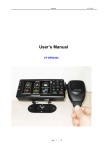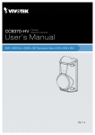
1
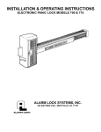
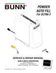
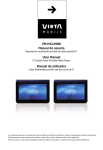
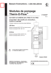
PROART DUAL AM/FMwww.altronics.com.au
TUNER WITH RS232
OPERATING INSTRUCTIONS
VIDEO DOOR INTERCOM
S 9406A Base Station and Camera System
S 9407 Additional Base Station
S 9409A Additional Camera Unit
Manufactured in China for Altronic Distributors Pty Ltd
Revised 17/10/12
VIDEO DOOR INTERCOM SYSTEM
Table Of Contents
Product overview and disclaimer
3
Product features and description of parts
4
Installation instructions
5
Cabling and wiring instructions and diagrams
6-8
Adding base stations and extra outdoor camera
6-8
Door strike connection
7
Operating instructions – door bell, intercom, menu
9
Setting time and date
9
Photo slideshow settings
10
Picture adjustment
11
USB device selection
11
Viewing visitor snapshots
12
Calendar and file management
12
Photo slideshow menu
13
Music and movie menus
13-14
Troubleshooting
14
Specifications and warranty
15
Page 2
VIDEO DOOR INTERCOM SYSTEM
Notice: Read the following instructions carefully before use.
• When you use the system for the first time, you must press the call button on the outdoor camera first, otherwise
the indoor monitor can not detect the outdoor camera.
• If the cabling configuration is incorrect it may damage the doorphone. Please read this manual carefully
• The indoor base station must be kept away from rain, moisture.
• Don’t dismantle the product. There are no user servicable parts inside. For repair, return to your place of purchase.
Included in the box (S 9406A full system):
• Indoor base station
• Outdoor camera
• Mounting bracket
• Mounting hardware
• Power supply
• 4-wire cable (20m)
NOTE: If you have purchased the S 9407 additional base station, an outdoor camera is not included.
If you have purchased S 9409A additional outdoor camera, the base station and power supply are not included. SD
Card and/or USB Memory stick are essential to the unit’s operation but are not included.
Overview
An ultra modern and stylish video intercom system featuring a colour 7” (18cm) TFT LCD screen. The all-weather
diecast aluminium door station features an LED for night time illumination. The hands-free LCD base unit monitor
enables intercom with the person at the door station, surveillance and activation of door release solenoids.
The indoor base station is also equipped with mini USB and SD card slots. These slots are used to connect storage
media devices that can be used to record photos of your visitors when they press the doorbell or call button. These
devices may also be used to playback music, videos or photo slideshows. For ease of use and effective operation, it is
recommended that an SD Card remain inserted at all times in the primary base station and any additional base station monitors. The unit has a mini USB A-type socket. To use a USB stick or a hard drive unit on which to store images
and music and movies, you need to purchase an appropriate adapter.(Refer to page 15)
The system may be expanded to include four LCD screens and two outdoor camera units for use in homes or offices
with more than one entrance. A call at a door station can be answered from any of the LCD monitor base stations.
For instructions on how to add extra base station video monitors (S 9409A) and outdoor cameras (S 9407), refer to
page 5.
Features
• Photo snapshot of visitors stored on SD Card or USB Memory Stick
• Adjustable brightness, contrast, colour and volume.
• Calendar and clock.
• Easy to install yourself.
• Movie playback.
• Music playback.
• Photo slideshows.
Page 3
VIDEO DOOR INTERCOM SYSTEM
Figure 1. Base Station
1. Screen: Used for displaying an image of your visitors, playback of movies and photo slideshows.
2. Up Button: Used to scroll through files on SD Card or USB.
3. Menu Button: Press this button to enter menu setting. In sub-menus press this button to exit.
4. Left Button: When playing from USB or SD card this reduces the volume.
5. Unlock Button: Press this button to operate the optional door strike to let your visitors in.
6. Speaker Button: Chime “Ding Dong” sound.
7. Player/Pause Button: Press to pause playback, to resume to normal playback press again.
8. Right Button: When playing from the USB or SD card this increases the volume.
9. Monitor Button: When a visitor presses the call button on the outdoor camera, press this button to speak to the visitor. In standby mode, press this button and the screen will display the picture outside the door for a few seconds and
store the image in the Monitor memory. Press and hold for 3 seconds to turn the monitor off or on.
10. Down Button: Used to scroll through files on SD Card or USB.
11. SD card slot: Insert SD card to store photos and files or play the files (photo, music, video).
12. USB slot: Insert USB memory stick to store photos and files or play the files (photos, music, video)
Adapters P1891 and P1932 required.
Note: The arrow buttons (numbered 2, 4, 8, and 10 on the base station monitor) act like cursor keys to navigate through and/or alter
the various functions and settings within each of the main menu options. This is in addition to allowing a user to scroll through a photo
or music or movie file directory on storage media. SD Card and/or USB Memory Stick are essential for S 9406A operation
(Not included).
Figure 2. Outdoor Camera
1. Loudspeaker: Allows you to communicate with
visitors.
1
2. Infra-red LED: Provides night time illumination
over a short distance.
2
3. Camera: Relays live video to the indoor base
station
3
4. Call button: Press to sound indoor chime and
activate indoor base station.
4
5. Microphone: Allows visitors to communicate
with you.
5
Page 4
VIDEO DOOR INTERCOM SYSTEM
Figure 3. Base Station Installation
Figure 4. Camera Installation
Installation
1. Determine the mounting locations for both outdoor camera and base station using the diagrams above. To ensure
people are within view when the camera is mounted, bear in mind the camera’s viewing angle. The typical wall
mounting height is 1450mm. Ensure you are satisfied with the viewing position of the camera and base station
before drilling any holes in your wall.
2. At the selected base station mounting location, attach the mounting bracket to the wall securely using the template
and hardware provided. In the centre of the bracket, drill a hole for the electrical and camera signal wiring.
3. Connect the wiring between the base station and camera as per diagrams.
4. Slide the base station against the mounting bracket until the hooks on the bracket secure the unit in place.
5. Switch on AC power to the unit.
6. Insert SD Card or USB Memory Stick (use P1891 and P1932) into appropriate slot. Without either of these storage
media connected, the device cannot function. i.e. store and retrieve photos.
Important mounting guidelines: Do not install the monitor and camera units where they will be exposed to dirt, moisture, excessive humidity, temperature (+40°C) or constant direct sunlight. Do not select a location where it will be
exposed to vibration. Select a location close to an AC power outlet where it is easy to view the screen and operate the
monitor.
Page 5
VIDEO DOOR INTERCOM SYSTEM
Figure 5. Connections between camera, base station, power and door strike.
Door Strike
(available separately)
Figure 6. Rear connection panel on base station.
Outdoor Camera
Figure 7. Connecting a second base station
Outdoor Camera
To Second
Base Station
Page 6
VIDEO DOOR INTERCOM SYSTEM
Cabling Requirements
Follow figures 5 and 6 when connecting the base station, camera and door strike. Before operation, double check that
all connections are correct. Incorrect wiring can damage the base station and camera.
Adding A Second Base Station
To add another base station monitor (S 9409A), simply use the 4-wire cable supplied with the additional base
station(s) to connect the new video monitor in parallel with the existing primary monitor.
Carefully insert the additional 4-wire cable terminals on top of the terminals already fitted into the primary base station rear connection panel (see Fig 7). The same colour wire goes into the same terminal connection, as per the guide
printed on the rear panel.
When the door bell is rung, BOTH video monitors chime and BOTH show the camera image of the caller at the door.
By pressing the ‘MONITOR’ button on either base station, the resident inside can speak to the visitor. To avoid audio
feedback, keep the base stations well separated. You will also need to connect the power adapter supplied with the
additional base station as per Fig 6. You can add up to THREE (3) additional base stations in this manner.
Adding A Second Outdoor Camera
To add another outdoor camera unit (S 9407), simply connect the 4-wire cable supplied with the accessory to existing
base station, as per Figure 6. Carefully insert the terminals from the extra 4-wire cable on top of the other terminals,
matching the wire colours to each terminal connection. Then join the camera to the base station by connecting their
cables. Only ONE (1) additional outdoor camera can be added to the primary base station in this manner, and only
ONE additional unit can be included in any multipl base station system. See figures 8 and 9.
Adding Both Outdoor Camera And Base Station
To add another base station monitor AND another outdoor camera, follow the procedure outlined above. However, it
might make sense to connect the wire and terminals from the extra camera to the second base station, since this
monitor should be located closer to the second entry, especially if you also install another optional door strike to the
second camera unit.
If the call button is pushed on door camera 2, the chimes will sound on BOTH base stations and the caller’s image will
be displayed on BOTH monitors. By pressing the ‘MONITOR’ button on either base station, the resident inside can
speak to the visitor. See figures 8 and 9.
WARNING: It is important to ensure that terminals from one connection point do NOT touch the terminals from the
adjacent connection points with different coloured wires on the base station rear panel, as this may short circuit the
system and lead to a malfunction.
NOTE: When purchasing additional outdoor cameras or base stations for your system, you must buy the S 9407 and S
9409A products. You cannot expand the system using elements of S 9406A. This is because S 9406A is a primary system and is coded as such. Additional cameras and base stations are coded to be slaves.
Optional Door Strike Connection
This unit will operate with a variety of door strikes. A switched 12V DC output is provided via the camera. These door
strikes are designed to have power momentarily applied to them. When the unlock button is pressed 12V will be
momentarily applied to the strike for 4-7 seconds allowing the visitor to enter the door. Once power is removed from
the strike, it reverts to the locked position. In the event of a power failure, the strike will remain locked.
Page 7
VIDEO DOOR INTERCOM SYSTEM
Figure 8. Connecting multiple base stations and cameras.
S 9406 PRIMARY SYSTEM
4 Wire
Outdoor
Camera
4 Wire
4 Wire
2 Wire
Door Strike
(available
separately)
S 9407 Indoor Monitor
S 9407 Indoor Monitor
Indoor Monitor
Power
15V DC
Power
15V DC
Power
15V DC
NOTE: A maximum of 4 base stations
and 2 cameras total.
4 Wire
4 Wire
Each base station monitor should be
placed in different rooms or offices.
When a visitor calls at either outdoor
camera, all monitors will chime and
display the visitors image.
S 9409
Outdoor
Camera
2 Wire
Door Strike
(available
separately)
S 9407 Indoor Monitor
Power
15V DC
Figure 9. Connecting multiple cameras to a single base station.
4 Wire
4 Wire
S 9409
Outdoor
Camera
2 Wire
Outdoor
Camera
2 Wire
Indoor Monitor
Door Strike
(available
separately)
Page 8
Door Strike
(available
separately)
Power
15V DC
VIDEO DOOR INTERCOM SYSTEM
Using The Doorbell
When someone presses the outdoor camera call button, their image is displayed automatically on the screen, and a
photo is taken and stored. To answer and talk to the person outside press
momentarily. This establishes two way,
hands free communication.
The screen will automatically switch off after 55 seconds. To cancel the conversation, press
To open the door press
(note: only available if door strike is fitted).
If you do not want to answer or when you are not in, the screen will close automatically after 20 seconds.
To display the street although no-one has pressed the outdoor camera call button, press
matically cancel after 55 seconds.
. The screen will auto-
Menu Settings
When a visitor presses the CALL button, or when the MONITOR button is pressed on the base station monitor panel, it
is possible to alter colour LCD screen settings by simply pressing the MENU button. You can tab through different
screen settings to be adjusted by pressing the MENU button again, and again, and using the left or right arrow buttons
to change the setting. The available settings in order are: Volume, Brightness, Contrast, and Colour. A yellow bar will
appear on screen and show the adjustment as you press the left or right ARROW buttons to a setting that suits your
needs.
Note: Adjusting settings from this menu is not the same as doing so from the SETTINGS menu, in that the changes
made here will not effect the settings that control the main menu screen's appearance, music, photo, and video playback. Changing settings in the manner described below only effect how the LCD monitor and audio speaker operate
when the call button is pressed.
Volume Adjust: This feature enables you to adjust the volume. The volume variable is 0-16. Press the
or
key to increase or decrease the volume.
Brightness Adjustment: This feature enables you to adjust the LCD screen brightness. The brightness variable is -7 to
9. Press the
or
keys to increase or decrease the brightness.
Contrast Adjustment: This feature enables you to adjust the contrast between light and dark parts of the LCD screen,
The contrast variable is -7 to 9. Use the
or
key to increase or decrease the contrast.
Colour Adjustment: This feature enables you to adjust the colour gradually. The colour variable is -7 to 9. Press the
or
key to adjust the colour.
Setting Time and Date
Page 9
VIDEO DOOR INTERCOM SYSTEM
Main Menu Operation
Settings
Note: Adjustments to various parameters made under the Settings menu will only effect music, photo
and video playback and the appearance of the main menu and standby screen. See page 9 for
instructions on how to adjust volume, brightness, contrast and colour parameters for the monitor
during an actual call at the door
Page 10
VIDEO DOOR INTERCOM SYSTEM
Device
Note:
If there is no SD Card or USB Memory Stick inserted into the device, this feature will not work.
Page 11
VIDEO DOOR INTERCOM SYSTEM
Monitor Function - Viewing visitor snapshots.
When someone rings the bell or presses the monitor key, it will store a snapshot photo automatically.
The photos are stored in the monitor folder.
Note: If no files are on the USB stick or SD card and invalid operation message will display.
Calendar
FILES - Search storage media directories
Note: If no files are on the USB stick or SD card and invalid operation message will display.
Page 12
VIDEO DOOR INTERCOM SYSTEM
PHOTO
Play Photo Slideshow
Play Photo Slideshow
key to rotate image
Note: If no files are on the USB stick or SD card and invalid operation message will display.
MUSIC
Play Music
Play Music
Note: If no files are on the USB stick or SD card and invalid operation message will display.
Page 13
VIDEO DOOR INTERCOM SYSTEM
MOVIEPlay Movie
Play Video
Note: If no files are on the USB stick or SD card and invalid operation message will display.
Troubleshooting
The monitor will not switch on:
Ensure the monitor is correctly plugged in to the power. Make sure the adaptor plug is properly pushed into the power
outlet.
The monitor is switched on but no image is displayed:
Check the wire connections between the camera and the monitor. Adjust brightness and contrast in the MENU.
Poor picture quality:
Adjust brightness and contrast in the MENU. Make sure there is no direct light preventing you from seeing the monitor
image. Check the orientation of the camera (no back lighting etc.).
Door chime volume too low:
Adjust the volume in the MENU
Door strike does not work:
Check the connections between the door strike and the camera. Refer to the door strike instructions.
Check the door strike is suitable for 12V 0.5A switching output. The door strike must only open when voltage is
applied, other configurations (such as door strikes which are constantly powered) are not suitable. If this is not the
case you must change the door strike to an Altronics S 5385 or S 5387.
Interference on the line:
The base station may be picking up interference from other electronic devices located around it. Move the base station or the other electronic devices to another location.
No audio between camera and base station:
Ensure the microphone on the camera is not obstructed.
Check audio connection between camera and base station.
Page 14
VIDEO DOOR INTERCOM SYSTEM
Specifications
Indoor base station (LCD monitor)
Supply voltage: ......................................................................................................................15V 1.0A Ripple <80mVp-p
Current consumption: .......................................................................................................................... 520mA + 100mA
Operating temperature: ............................................................................................................................-10°V - +50°C
Operating humidity: ..........................................................................................................................................85% MAX
Signal output: ....................................................................................................Built in stereo speakers (1 watts x 2ch)
Screen size: ................................................................................................................................................7” (diagonal)
Card type: ........................................................................................................................................SD/MMC/USB mini
Movie/photo files: ..........................................................JPEG, MP3/WMA, VOB, MPEG1, AVI, XVID, DIVX4.x, DIVX5.X
Colour configuration: ......................................................................................................................................RGB.delta
Video system: ..................................................................................................................................................PAL/NTSC
External dimensions: ......................................................................................................197(L) x 187 (W) x 20 (H) mm
Outdoor camera
Current consumption: ........................................................................................................................................<300mA
Camera angle: ..........................................................................................................................................................≈50°
LED illumination: ........................................................................................................................................................Yes
Operating temperature:..............................................................................................................................-20°C to 50°C
External dimensions:..........................................................................................................122(L) x 73 (W) x 44 (H) mm
Optional accessories
S 9407 Additional base station
S 9409A Additional outdoor camera
S 5385 or S 5387 Optional door strike
DA0320 SD Card 4Gb (Larger capacity cards available)
D 0400A USB 2.0 Memory stick 4Gb (Larger capacity sticks available)
P 1891 USB A Male to USB Mini adaptor cable 1 metre
P 1932 USB A Female-Female adaptor
Note:
Both P 1891 and P 1932 are required for connection of USB Memory stick or HDD
Page 15
VIDEO DOOR INTERCOM SYSTEM
Altronic Distributors warrants this product for one year from date of purchase from Altronics or its resellers
to the consumer. If this item is part of an installation or another product, please contact the installer or
supplier for your warranty.
During the warranty period, we undertake to repair or replace your product at no charge if found to be
defective due to a manufacturing fault. The warranty excludes damage by misuse or incorrect installation
(i.e. failure to install and operate device according to specifications in the supplied instruction manual),
neglect, shipping accident, or no fault found, nor by use in a way or manner not intended by the supplier.
For repair or service please contact your PLACE OF PURCHASE.
If this item was purchased directly from Altronics please make a warranty claim by:
1. FOR MAIL ORDER CUSTOMERS (includes school and trade orders),
a) Ringing us on 1300 797 007 and quoting your tax invoice number.
b) Upon contacting Altronics, we will issue an R.A. (Return Authorisation).
As Altronics have a number of service agents throughout Australia,
a copy of the R.A. will be emailed, faxed or mailed to you with full instructions
of how and where to send the goods. The freight for shipping goods back to
Altronics for all repairs is at the customers expense.
c) A copy of the R.A. form, (or at the very minimum, the R.A. number) must
accompany the goods to effect the repair.
d) Altronics will pay the return freight to the customer where the warranty claim
has been accepted.
e) Please quote the R.A. number in any correspondence to us.
2. FOR OVER THE COUNTER PURCHASES to make a warranty claim,
please return the goods to us in any of our stores, with a copy of your
proof of purchase (tax invoice).
a) Upon leaving the goods at one of our stores, an R.A. number
will be issued to you.
b) Once repaired, you will be contacted, advising that the goods are ready to be
collected from the store.
It is at Altronics discretion as to whether the goods will be repaired or replaced (whilst under warranty);
and as to whether identical goods will be used to replace the item due to changes of models / products.
Note: Under no circumstances should you attempt to repair the device yourself or via a non-authorised
Altronics service centre, as this will invalidate the warranty!
Our goods come with guarantees that cannot be excluded under the Australian Consumer Law. You are
entitled to a replacement or refund for a major failure and for compensation for any other reasonably
foreseeable loss or damage. You are also entitled to have the goods repaired or replaced if the goods fail
to be of acceptable quality and the failure does not amount to a major failure.
NOT FIELD SERVICEABLE.
Distributed by Altronic Distributors Pty. Ltd. Perth. Western Australia.
Phone: 1300 780 999 Fax: 1300 790 999 Internet: www.altronics.com.au
Page 16