1
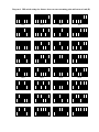
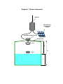
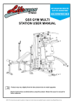
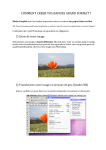
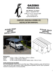
AQUAGAUGETM Ultrasonic Liquid Level Sensor
Installation and Operating Instructions.
______________________________________________________
1. Locate a suitable mounting point in the centre of the top of the tank and
ensure that there is an opening at least 50mm in diameter to
accommodate the sensor housing.
2. Measure the distance between the proposed mounting point and the
bottom of the tank, i.e. distance H in diagram 2.
3. Set the corresponding 6 DIP switches shown in figure 1 and diagram 1 to
the height, H, of the tank.
4. Mount the sensor on the tank such that the face of the ultrasonic element
is parallel to the surface of the liquid in the tank.
5. Connect the 4-pin plug on the cable from the sensor case to the socket
on the bottom of the M2M unit.
Operating Limitations
The normal detecting range, D, of the ultrasonic sensor is 30 to 350 cm. The
range 0-30 cm is a dead-band and above about 350 cm the signal is often too
weak to be measured. The resolution of the sensor is 1cm.
The distance, D, measured by the sensor is automatically subtracted from the
height of the tank, H, to give the depth, L, of liquid that is relayed to the M2M
unit, i.e. L = H – D
If distance D is read as more than H then a reading of 9999 cm will be
returned for L.
Erratic or false readings can be caused by echoes from the side of the tank,
contamination on the sensor face, extraneous acoustic signals, foam and
turbulence on the surface of the liquid. The calculated distance to the liquid
surface is based on the speed of sound in dry air at 25oC. The true speed of
sound Vair, can vary with temperature Tc according to the following equation:
o
Vair = 331.5+ (0.6⋅ TC ) m/s . Over the range 0-50 C the maximum error is less
than 10%. Variation in atmospheric humidity has a much smaller effect;
however if a relatively volatile liquid is to be measured then the speed of
sound can vary considerably if the tank is saturated with liquid vapour.
DIP
switches
Figure 1.
Diagram 1. DIP switch settings for distance between sensor mounting point and bottom of tank (H)
50cm
55cm
60cm
65cm
70cm
75cm
80cm
85cm
90cm
95cm
100cm
105cm
110cm
115cm
120cm
125cm
130cm
135cm
140cm
145cm
150cm
155cm
160cm
165cm
170cm
175cm
180cm
185cm
190cm
195cm
200cm
205cm
210cm
215cm
220cm
225cm
230cm
235cm
240cm
245cm
250cm
255cm
260cm
265cm
270cm
275cm
280cm
285cm
290cm
295cm
300cm
305cm
310cm
315cm
320cm
325cm
330cm
335cm
340cm
345cm
350cm
355cm
360cm
365cm
Diagram 2. System components
M2M unit
Solar panel for
rechargeable
battery
Ultrasonic distance sensor
Storage tank
Pulse
D
H
Echo
L