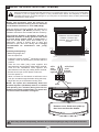
1
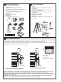
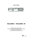
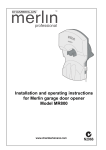
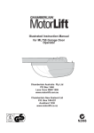
www.chamberlaindiy.com.au
MLR500/MLR750
Rolling Garage Door Opener
Installation and Operating Instructions
Owners Copy: Please keep these instructions for future reference
This manual contains IMPORTANT SAFETY information
DO NOT PROCEED WITH THE INSTALLATION BEFORE READING THOROUGHLY
START BY READING THESE IMPORTANT SAFETY INSTRUCTIONS
WARNING
• Failure to comply with the following instructions may result in serious personal injury or property damage.
• Read and follow all instructions carefully.
• The garage door opener is designed and tested to offer safe service provided it is installed and
operated in strict accordance with the instructions in this manual.
These safety alert symbols mean WARNING : A possible risk to personal safety or
property damage exists.
Keep garage door balanced. Do not let the
garage door opener compensate for a
binding or sticking garage door. Sticking,
binding or unbalanced doors must be
repaired before installing this opener.
The opener must not be used on a wicket
door (door within a door).
The Protector SystemTM must be used for
all installations where the closing force
as measured on the bottom of the door is
over 400N (40kgf). Excessive force will
interfere with the proper operation of the
safety reverse system or damage the
garage door.
Do not wear rings, watches or loose
clothing while installing or servicing a
garage door opener.
Frequently examine the door installation,
in particular cable, springs and mountings
for signs of wear, damage or imbalance. Do
not use if repair or adjustment is needed
since springs and hardware are under
extreme tension and a fault can cause
serious personal injury.
After installation, ensure that the parts of
the door do not extend over public
footpaths or roads.
Install the wireless wall control (or any
additional wall control) in a location where
the garage door is visible, at a height of
at least 1.5m and out of the reach of
children. Do not allow children to operate
push button(s) or transmitter(s). Serious
personal injury from a closing garage door
may result from misuse of the opener.
To avoid serious personal injury from
entanglement, remove all ropes, chains
and locks connected to the garage door
before installing the door opener.
Installation and wiring must be in
compliance with your local building and
electrical codes.
Permanently fasten the Warning Labels
in prominent places, adjacent to wall
controls and manual release mechanisms
as a reminder of safe operating procedures.
The safety reverse system test is very
important. Your garage door MUST reverse
on contact with a 40mm obstacle placed on
the floor. Failure to properly adjust the
opener may result in serious personal injury
from a closing garage door. Repeat the test
once a month and make any necessary
adjustments.
Activate opener only when the door is in
full view, free of obstructions and the
opener is properly adjusted. No one
should enter or leave the garage while
the door is in motion.
Do not allow children to play near the
door, or door controls.
This opener should not be installed in a
damp or wet space exposed to weather.
Disconnect electric power to the garage
door opener before making repairs or
removing covers.
This appliance is not intended for use by
persons (including children) with reduced
physical, sensory or mental capabilities, lack
of experience and knowledge, unless they
have been given supervision or instruction
concerning use of the appliance by a person
responsible for their safety.
KEEP THESE INSTRUCTIONS
NOTE: If your garage has no service entrance door, a 1702AML outside quick release must be installed.
This accessory allows manual operation of the garage door from outside in case of power failure.
CONTENTS
PAGE
SAFETY INSTRUCTIONS . . . . . . . .1
CARTON INVENTORY . . . . . . . . . .2
TOOLS REQUIRED . . . . . . . . . . . .2
DOOR REQUIREMENTS . . . . . . . .2
PREPARE & TEST THE DOOR . .3-4
INSTALLATION . . . . . . . . . . . . . .5-6
CONNECT ELECTRIC POWER . . .7
ADJUSTMENT . . . . . . . . . . . . . . .7-8
INSTALL THE PROTECTOR
SYSTEM (IR BEAMS) . . . . . . . . . . .9
AUTO-CLOSE . . . . . . . . . . . . . . . .10
WIRELESS PROGRAMMING .10-11
SPECIAL FEATURES . . . . . . . . . .12
ACCESSORIES . . . . . . . . . . . . . . .12
TROUBLESHOOTING . . . . . . . . . .13
OPERATION OF YOUR OPENER 14
CARE OF YOUR OPENER . . . . . .14
MAINTENANCE OF YOUR OPENER 14
SPECIFICATIONS . . . . . . . . . . . . .14
WARRANTY . . . . . . . . . . . . . . . . .15
1
1 CARTON INVENTORY
2 TOOLS REQUIRED
1.
2.
3.
4.
5.
Instruction manual (this document)
Warning and risk of entrapment labels
Hardware bag
Release handle, cord and risk of entrapment card
2 x 3 Channel mini transmitter - MLR750
1 x 3 Channel mini transmitter - MLR500
6. Wall or visor mounted transmitter
7. Stop collar
8. Clamp bracket and plate
9. Weight bar
10. 2 x Extension poles & 1 x brace
1
2
1. Ladder
2. Adjustable wrench for U-bolts already installed
on the door
3. 8mm socket, 10mm socket and 13mm extended
socket and socket wrench
4. 300mm socket extension (for minimum side-room
installations)
5. Drill and 5.5mm drill bit
6. Phillips-head screwdriver
7. Marker pen
8. Door stand or similar device to safely support door
(not shown)
3
5
4
6
7
8
10
9
3 DOOR REQUIREMENTS
The maximum allowable door height is 3.5m with a maximum curtain area of 13.5 m² (MLR500) or 15m2 (MLR750)
(door height in metres multiplied by the width in metres). The door must be spring balanced.
The Protector System™ (IR Beams) must be installed if the force at the edge of the closing door exceeds 400N
(40kgf). Door axle diameter must not exceed 35mm.
Door area
h x w = m2
eg. 2.5 x 3 = 7.5m2
fig B
fig A
Direct clamping method
Independent clamping method
Ensure that there is at least 45mm from the edge of the curtain to the edge of the bracket. If the roller door
drum is on the edge of the curtain or is a smaller diameter, additional clearance may be required.
If the drum is more than 60mm from the curtain edge or of a smaller diameter, extension poles may be
required (see section 7).
Different drum and bracket types may result in the minimum side room clearance not being possible and
extension poles being required. Ensure there is a power point near the opener.
2
4 TESTING THE DOOR
Complete the following test to ensure your door is well
balanced, and not sticking or binding:
• Disable all locks and remove any ropes connected to
the garage door.
• Lift the door to about halfway and then release it. The
door should remain suspended entirely by its spring.
• Raise and lower the door to determine if there are any
sticking or binding points (20 kgf is the absolute maximum
allowable to raise or lower the door in any position).
• If your door does not hold in place or it binds or sticks,
call a qualified door technician before installing the opener.
5 INSTALLING THE STOP COLLAR
• Install stop bracket collar on the opposite end to
where the opener is to be installed.
Non opener side
• Fit the stop bracket hard against the boss of the door
drum. Ensure the U-bolt holding the door axle to the
door bracket is tightly secured.
SAFETY CHECK!
Is stop collar installed?
YES
Proceed to the next step
NO
Install the stop collar
before proceeding
6 INSTALLING THE WEIGHT BAR (PROVIDED)
• Place the weight bar in the centre of the door.
• If the door curtain does not have a lifting handle you
will need to drill two 5.5mm holes through the two
marked positions, then place the weight bar on the
inside of the door.
• Use the 5mm bolts, washers and nuts (provided) to
fasten the weight bar in place.
NOTE: If the door has a lifting handle, remove the
handle, nuts & bolts. Place weight bar over the
handle holes, insert extended bolts through the
weight bar & fasten handle back in place.
3
Opener side
7 PREPARING THE OPENER
Set opener position (left or right hand)
For left hand side installations
the wire jumper should be removed.
For right hand side installations
the wire jumper should be in place
(factory installed).
Extension pole
Attaching the extension poles (if required)
• Insert the extension poles into the gear.
• Align the extension pole holes with the gear holes.
• Using the screws provided, secure the extension poles.
Reinforcing Brace
• Align the holes of the reinforcing brace with the two
holes as shown and fix in place using the screws
provided.
Drive leg
Reinforcing brace must be used.
8 PINNING THE DOOR
Note: A ballooning door may delay the safety reversal
response and can compromise garage door security.
Free curtain
Ballooning
Door closed
Door can be lifted
Add fasteners here
• To remedy any ballooning place self tapping metal screws
or rivets where the curtain leaves the roll. Secure these
through the curtain into the drum wheel at each end of
the roll.
• After determining the correct fastener location as shown,
lift the door approximately half a turn from the closed
position to allow access for drilling.
4
Door secure
9 INSTALLATION STEPS
FOR RIGHT HAND INSTALLATIONS
• Ensure that the opener position jumper (wire connector) is
installed (refer Section 7).
• Place the opener in manual release mode (refer Section 11).
• Open the roller door fully. For safety, tie a rope around the door
(as shown).
• Mark the position of the door axle on the right hand door bracket.
Ensure that the U-bolt on the left hand (non opener) side of
the door is secure.
• Carefully remove the U-bolt on the right hand side, checking that
the spring tension inside the roller door is not being released.
• You will need assistance for the following steps. To safely
support the door slide or lift the door axle clear of the door
bracket, supporting the door weight with a door stand or similar
device. Then slip the door opener over the door axle.
NOTE: The forks should engage either side of the support
spoke.
• Direct clamping method (refer fig 1): Place the opener and
door axle onto the door bracket in the position that the door axle
was originally. Clamp the opener to the door axle through the door
bracket with the bracket plate, 8mm bolts and nuts (supplied).
Tighten sufficiently to fasten the opener firmly to the axle i.e.
25Nm-28Nm.
• Remove any ropes used.
Rope
SAFETY CHECK!
Are all brackets and door
fastenings tightly secured?
YES: proceed to the next
step
NO: tighten any loose
fastenings before
proceeding
fig 1
• Independent clamping method: If the side room exceeds
95mm, clamp independently to the door axle as illustrated in
section 3 (fig A) using 2 separate clamps.
FOR LEFT HAND INSTALLATIONS
• Ensure that the opener position jumper (wire connector) is
removed (refer Section 7).
• Place the opener in manual release mode (refer Section 11).
• Open the roller door fully. For safety, tie a rope around the door
(as shown).
• Mark the position of the door axle on the left hand door bracket.
Ensure that the U-bolt on the right hand side (non opener)
of the door is secure.
• Carefully remove the U-bolt on the left hand side, checking that
the spring tension inside the roller door is not being released.
• You will need assistance for the following steps. To safely
support the door slide or lift the door axle clear of the door
bracket supporting the door weight with a door stand or similar
device. Then slip the opener over the door axle (as shown).
NOTE: The forks should engage either side of the support
spoke.
• Direct clamping method (refer fig 2): Place the opener and
door axle onto the door bracket in the position that the door axle
was originally. Clamp the opener to the door axle through the
door bracket with the bracket plate, 8mm bolts and nuts
(supplied). Tighten sufficiently to fasten the opener firmly to the
axle i.e. 25Nm-28Nm.
• Remove any ropes used.
• Independent clamping method: If the side room exceeds
95mm, clamp independently to the door axle as illustrated in
section 3 (fig A) using 2 separate clamps.
5
fig 2
10 ATTACH THE RELEASE HANDLE AND CORD
• Thread one end of the rope through the hole in the top of
the red handle so “NOTICE” reads right side up as
shown.
• Secure with an overhand knot at least 25mm from the
end of the rope to prevent slipping.
• Thread the other end of the rope through the loop of the
manual release cable.
• Adjust the rope length so the handle is no higher than
1.8m above the floor. Secure with an overhand knot. If
the door is greater than 2.5m in height the release cord
extension kit accessory is required.
NOTE: Final adjustment of the handle height should be
completed after the opener is installed. If it is
necessary to cut the rope, heat seal the cut end to
prevent unravelling.
Release cord
Rope
Manual release
Warning label
Overhand knot
Release handle
11 OPERATING THE MANUAL RELEASE
pull down
Disable all locks and remove any ropes
connected to the garage door. Take care
when operating the manual release as an open
door may fall rapidly due to weak or broken
springs, or being out of balance.
To disengage the opener
Pull the release cord down once until you hear a
clicking sound. The door is now in manual mode and
may be opened or closed.
release cord
To re-engage the opener
To re-engage the opener, pull the release cord down
until you hear a clicking sound, the motor is now ready
for operation.
6
12 SETTING THE LIMITS
Travel limits regulate the points at which the door will
stop when moving UP or DOWN. During the set up
procedure, the motor will run and operate the door.
The opener must be fully installed on the door and all
installation steps completed before proceeding.
fig 1
The opener will operate during this
procedure. Make sure the door is clear of
obstruction. Ensure your hands are away from
any moving parts before activating the door.
www.chamberlaindiy.com.au
MLR500
PREPARATION:
• Position the door about half way and engage the
opener (section 11).
• Remove the lens cover from the opener (fig 1).
• Connect the opener to a 240VAC power point and
turn on.
SETTING THE TOP LIMIT:
• Press and hold the black limit button until the
orange indicator LED starts flashing slowly, and
then release. The courtesy LEDs will go to low
illumination.
Ensure motor is engaged
(refer section 11)
• Press and hold the black limit button, until the door
reaches the desired open position. If set too high,
adjust down using the purple learn button (make
sure there is enough room for your vehicle to pass
under).
Press and hold black button
Flashing orange LED
courtesy LED dim
SETTING THE BOTTOM LIMIT:
Use the black button to adjust up
(use purple down to adjust if required)
• Press and release the green start button, this sets
the UP limit and begins closing the door, once the
opener starts to move down, IMMEDIATELY press
and hold the purple learn button until the door
reaches the desired closed position, then release
button. For fine adjustment press and release the
purple learn button to inch down.
Press start button located on the
bottom of motor, then immediately
press the purple button.
Press and hold the purple button
until the door is closed.
Use the black button to adjust up
if required.
SAVE AND TEST:
• Press and release the green start button, this sets
the DOWN position and begins opening the door
to the fully open position.
• Close and open the door 3 or 4 times using the
green start button to confirm the limit settings.
Courtesy LEDs should now be fully illuminated.
Repeat the above procedure if necessary.
Press the green start button to
open the door and save the limits.
Press the green start button to
close the door and complete test.
Orange LED will go out and courtesy
LEDs will light up brightly.
NOTE:The force must now be set in order to
complete your installation (refer section 13).
7
13 SETTING THE FORCE
The force, as measured on the closing edge of the door,
should not exceed 400N (40kg). If the closing force is
measured to more than 400N, The Protector SystemTM
(IR Beams) must be installed (refer section 16).
The force setting regulates the amount of power
required to open and close the door.
• Door should be closed before proceeding.
• Press the purple button twice to enter the opener into
force adjustment mode. The indicator LED will flash
quickly.
• Press the green start button on the bottom of the
opener. The door will travel to the up limit. Press the
green start button again, the door will travel to the
down limit. The indicator LED will stop flashing when
the force has been learned.
• The door must travel through a complete cycle, up and
down, in order for the force to be set properly. If the
opener cannot open and close your door fully,
examine your door to ensure that it is balanced
properly and is not sticking or binding (refer section 4).
Press the purple learn button
twice
FAST flashing orange LED
Press the green start
button to open the door.
Press the green start
button to close the door.
14 TESTING THE SAFETY REVERSE SYSTEM
The safety reverse system test is important. The garage
door must reverse on contact with a 40mm obstacle laid
flat on the floor. Failure to properly adjust the opener may
result in serious personal injury from a closing garage door.
Operate the door in the down direction. The door must reverse
upon contact with the obstacle. If the door stops on the obstacle,
remove obstacle and repeat limit and force setting (sections 12 &
13). Repeat testing procedure of the safety reverse system.
40mm test obstacle
This test should be repeated monthly to ensure the safe operation of your opener.
15 FIXING WARNING LABELS
Once you have completed your installation and
successfully carried out the safety reverse system
test (outlined above), install the warning labels
provided with your opener as shown.
The risk of entrapment label must be installed
adjacent to the release handle at a height of less than
1.8m from the floor.
The WARNING label must be installed in a prominent
place near any fixed control.
Any fixed wall control or wireless door control must be
mounted at a height of no less than 1.5m out of the
reach of children.
Ensure the instruction card concerning the manual
release of the door is attached to the rope as detailed
in section 10.
Read the safety instructions (page 1) for further
details concerning safety.
STANDARD INSTALLATION COMPLETE
8
16 INSTALL THE PROTECTOR SYSTEM™ (IR BEAMS)
SAFETY FIRST!
Whilst Chamberlain have engineered safety features into your garage door opener, we urge you to consider fitting
IR Beams to your new garage door opener. In many countries these devices are compulsory to assist in
preventing serious injury or property damage. For your own peace of mind and the safety of others please install
this inexpensive safety device.
NOTE: This accessory must be used for all
installations where the closing force as measured
on the bottom of the door is over 400N (40kgf).
After the opener has been installed and adjusted, the
Protector System™ (IR Beams) accessory can be
installed. Instructions are included with this accessory.
The Protector System™ (IR Beams) provides an
additional measure of safety against a small child
or animal being trapped under a garage door. It
uses an infra-red beam, which when broken by an
obstruction, causes a closing door to open and
prevents an open door from closing and is strongly
recommended for homeowners with young
children.
IR Beams must be installed
to detect a 100mm high
obstacle at any point along
the floor.
Red LED
MUST BE ON
Installing and adjusting:
• Close the garage door.
• Turn the opener off.
• Install the Protector SystemTM (IR Beams) using the
brackets, wires and instructions provided with the
product.
• Twist the two white (only) wires together and
terminate them into the white “safety beam” terminal.
Twist the two white/black wires together and
terminate them into the grey “safety beam” terminal.
• Ensure the trim pot on the opener is set to 0s.
• Turn the opener on.
• Allow 5 minutes for the beams to self-learn to the
unit, (do not walk through the beam during this time).
• Adjust the trim pot to the desired closing time.
Red LED
MUST BE ON
IR Beam
IR Beam
white
wires
twisted
together
NOTE: The opener will automatically detect the
Protector SystemTM (IR Beams) when it is installed
and operating for 5 minutes (during this time the
beams must remain unobstructed). The opener will
not close unless the beams are aligned.
white
white/black
wires
twisted
together
grey
Remove cover: Push cover plate up,
then lever out from the button.
Door may operate unexpectedly, therefore do not allow anything to stay in the path of the door.
9
17 SETTING AUTO CLOSE (OPTIONAL)
NOTE: The Protector SystemTM (IR Beams) MUST be installed to enable this feature.
The auto close feature will automatically close the garage door after the preset time. The time can be adjusted up
to 180 seconds using the trim pot located on the control board. Auto close can be disabled by adjusting the trim
pot to the minimum setting.
Auto close is NOT recommended for households with young children.
Installing and adjusting:
• Close the garage door.
• Turn the opener off.
• Remove the cover.
• Ensure the trim pot on the opener is set to the minimum setting.
• Install the Protector SystemTM (IR Beams) using the brackets, wires and
instructions provided with the product. Twist the two white (only) wires together
and terminate them into the white (2) terminal. Twist the two white/black wires
together and terminate them into the grey (3) terminal.
• Turn the opener on.
• Allow 5 minutes for the beams to self-learn to the unit (do not walk through the beam during this time).
Do not adjust the trim pot whilst the door is in the open position.
Door will activate when the trim pot is adjusted in the open position
• Ensure the door is in the closed position, then adjust the trim pot to the desired closing time by turning the “auto
close (TTC)” trim pot anti-clockwise.
Test the timer close feature:
• Once the timer is set open the door and allow it to close via the “timer to close” feature.
NOTE: If more or less time is desired, adjust the trim pot whilst the door is closed then repeat test
outlined above.
18 WIRELESS PROGRAMMING (OPTIONAL ACCESSORIES)
NOTE: Your transmitter(s) have already been programmed into your opener.
Activate the opener only when door is in full view, free of obstruction and properly adjusted. No
one should enter or leave garage whilst door is in motion. Do not allow children to operate push
button(s) or transmitter(s). Do not allow children to play near the door.
Fix any wall control at a height of at least 1.5m and within sight of the door but away from any
moving parts.
ADDING transmitters using the learn button
• Press and hold down the transmitter button you wish
to program to the opener.
• The orange LED will flash continuously to indicate it is
receiving signal from the transmitter.
• Press and release the learn button on the opener.
• The courtesy LED will flash once.
• Ensure the door is clear of obstruction, then test the
transmitter.
DELETING ALL transmitter codes
NOTE: This deletes all learned transmitters.
• Press and hold the learn button until the
orange indicator light goes out (approximately 9 sec).
10
19 KEYLESS DEVICE PROGRAMMING
(OPTIONAL ACCESSORIES )
Learn button programming
1
Activate the opener only when the door is
in full view, free of obstruction and
properly adjusted. No one should enter or
leave garage whilst the door is in motion. Do not
allow children to operate push button(s) or
transmitter(s). Do not allow children to play near
the door.
Wireless Keypad 8747AML
Press the purple
(learn) button, orange
LED will light
Limits
2
Enter 4 digit PIN at
keypad (within 30s)
3
Learn
Using the (purple) learn button:
1. Press and release the (purple) learn button (1) on the
opener (the orange LED will light).
2. Within 30 seconds, enter a four digit personal
identification number (PIN) of your choice on the
keypad (2), then press and hold the ENTER button.
3. Release the button when the opener courtesy LEDs
flash once (3) (the code is learned).
Orange LED will turn off
and courtesy LEDs will
flash once
Limits
Programming via multi-function control panel
1
Enter 4 digit PIN at
keypad (within 30s)
2
Alternate programming method using the multifunction control panel (optional accessory):
Press and hold down
LIGHT button on the
motion detecting
control panel
LOCK
LIGHT
NOTE: This method requires two people if the
keyless entry is already mounted outside the
garage.
3
With the LIGHT button
pressed, press and
hold the PUSH BAR on
the motion detecting
control panel
LOCK
LIGHT
1. Enter a four digit personal identification number (PIN)
of your choice on the keypad (then press and hold
ENTER).
2. While holding the ENTER button, press and hold the
LIGHT button on the multi-function control panel.
3. Continue holding the ENTER and LIGHT buttons while
you press the push bar on the multi-function control
panel (all three buttons are held).
4. Release buttons when the opener courtesy LEDs
flash once.
Wireless fingerprint access system C379
4
Learn
Release the button when
the courtesy LEDs flash
once
Limits
Press the purple
(learn) button, orange
LED will light
Limits
#
ENROLL
SEND
Full instructions are available with this accessory.
Once you have enrolled your user into the C379 you
can program the unit into your opener.
Slide the cover plate
up (A)
ENROLL
PASS
FAIL
READY
RETRY
Swipe finger at a
steady speed (B)
$
Using the learn button:
1. Press and release the learn button on the opener, the
orange LED will light.
2. Within 30 seconds, slide the cover of the C379 up as
illustrated (A). Swipe your finger on the reader head at
a steady speed (B) until the yellow LED turns on (C).
3. When the courtesy LEDs flash it has learned the
code. Ensure there are no obstacles in the path of the
door, then press the send button (D) to test the door.
%
ENROLL
SEND
ENROLL
PASS
FAIL
READY
RETRY
Limits
Yellow LED will indicate
successful swipe (C)
Courtesy LEDs
will flash once
&
Test reader by pressing
the send button (D)
11
20 SPECIAL FEATURES
2
1
1.Multifunction control panel
Connect white/red wire to the red “wired wall
control” quick connect terminal and the white wire
to the white “wired wall control” quick connect
terminal.
2.The Protector System™ (IR Beams)
Connect both white wires to the white “safety beam”
quick connect terminal and both white/black wires to
the grey “safety beam” quick connect terminal.
3. Standby power unit
Connects via plug (fig 1) and lead provided with the
unit into the base of the opener.
LOCK
LIGHT
fig 1
Note: Timed auto-close function is enabled by
turning the dial to the required time. The Protector
SystemTM (IR Beams) must be installed before
using this function. Timer trim pot must be set to
zero when the Protector SystemTM (IR Beams) is
installed.
3
Remove tab
at base of opener
before connecting
Standby power unit
21 ACCESSORIES
LOCK
LIGHT
1
5
6
4
3
2
7
1. Model C379 Fingerprint keyless entrypad
7. Model 760AML Outdoor keyswitch
2. Model 84330AML 1 channel transmitter
8. Model 1702AML Keyed outdoor emergency release
3. Model 84335AML 3 channel mini transmitter
9. Model 770AML The Protector SystemTM (IR Beams)
4. Model 8747AML Keyless entry system
10. Model C475 Standby power unit
5. Model 75AML Illuminated button
6. Model 845AML Multi-function control panel
Transmitter wall mount bracket
• Attach bracket to wall using the two flat head screws
provided.
• Slide the transmitter onto bracket.
• Fix the warning against entrapment label near the wall control
(refer section 15).
NOTE: Do not over tighten screws, allow enough clearance to
slide transmitter down onto the bracket.
12
TROUBLESHOOTING
1.The opener doesn't operate from either the
GREEN start button or the transmitters:
• Does the opener have electric power? Plug a lamp into
the outlet. If it doesn't light, check the fuse box.
• Have you disabled all door locks? Review installation
instruction warnings on page 1.
• Is there a build-up of ice or snow under the door? The
door may be frozen to the ground. Remove any
restriction.
• The garage door spring may be broken. Have it
replaced.
2. Opener operates from the transmitter, but not
from the wired wall control (optional accessory):
• Is the wall control lit? If not, reverse the two wires. If
the opener runs, check for a faulty wire connection at
the wall control, a short under the staples, or a broken
wire.
• Are the wiring connections correct? Refer to wired wall
control instructions.
3. The door operates from the GREEN start button
or wired wall control, but not from the wireless
wall control or transmitter:
• If the wired wall control is installed and it is flashing,
ensure the lock feature is off.
• Program the opener to match the transmitter code
(refer section 18). Repeat with all transmitters.
4. The transmitter has short range:
• Change the location of the transmitter in your car.
• Check to be sure the antenna on the bottom of the
opener extends fully downward.
• Some installations may have shorter range due to a
metal door, foil backed insulation, or metal garage
siding.
5. The garage door opens and closes by itself:
• Be sure that all transmitter push buttons are off.
• If the wired wall control (optional accessory) is
installed, remove the bell wire from the wired wall
control terminals and operate from the GREEN start
button or transmitter. If this solves the problem, the
wired wall control is faulty (replace), or there is an
intermittent short on the wire between the wired wall
control and the opener.
• Clear memory and re-program all wireless wall
controls and transmitters.
6. The door reverses and stops before opening
completely:
• Is something obstructing the door? Is it out of balance,
or are the springs broken? Remove the obstruction or
repair the door.
• Repeat the limit and force setting in section 12 & 13,
Repeat safety reverse test after adjustments (refer
section 14).
7. The door reverses for no apparent reason and
opener lights blink for 5 seconds after reversing:
• Check the Protector SystemTM (IR Beams), if
installed. Correct alignment if the red light on the beam
is solid.
8. The door opens but won't close or reverses while
closing:
• Is something obstructing the door? Pull the manual
release handle. Operate the door manually. If it is
unbalanced or binding, call a trained door systems
technician.
• Clear any ice or snow from the garage floor area where
the door closes.
• Repeat the limit and force setting in section 12 & 13.
Repeat safety reverse test after adjustments (refer
section 14).
• If The Protector SystemTM (IR Beams) is installed check
the beams, both red LEDs should be on.
9. The opener strains to operate door:
• The door may be out of balance or the springs may be
broken. Close the door and use the manual release to
disconnect the door. Open and close the door manually.
A properly balanced door will stay in any point of travel
while being supported entirely by its springs. If it does
not, disconnect the opener and call a trained door
systems technician.
10. The opener motor hums briefly, then won't work:
• Check that the door is not in manual release mode,
refer section 11.
• The garage door springs may be broken. See point 9.
• If the problem occurs on the first operation of the
opener, the door may be locked. Disable any door locks.
11. The opener won't operate due to power failure:
• Use the manual release handle to disconnect the door.
The door can be opened and closed manually. When
power is restored, re-engage the opener, refer section
11.
12. Setting the limits manually:
a.Check that the opener position jumper is correct, refer
Section 7.
b.Press and hold the BLACK button until the orange
indicator light starts flashing slowly then release.
c.Press the BLACK button to move the door UP or the
PURPLE button to move the door DOWN until the
door reaches the desired UP limit. Ensuring there is
enough clearance for your vehicle.
d.Press the GREEN start button. This sets the UP limit
and begins closing the door. Immediately press either
the PURPLE or the BLACK button. The door will stop.
Adjust the desired DOWN limit using the BLACK and
the PURPLE buttons. Check to be sure the door is fully
closed without applying excessive pressure to the door
curtain. Press the GREEN start button. This sets the
DOWN limit and begins opening the door.
NOTE: If neither the BLACK or the PURPLE button is
pressed, the door will reverse off the floor and the
DOWN travel limit will be set automatically.
e.Open and close the door with the GREEN start button,
transmitter or wall control 2 or 3 times.
• If the door does not stop in the desired UP limit or
reverses before the door stops at the DOWN limit,
proceed to setting the force, section 13.
• If the door still does not stop at the desired limits, is
something obstructing the door? Disengage the opener.
Open and close the door manually. If it is unbalanced
or binding, call a trained door systems technician.
• If the door stops at both the desired UP and DOWN
limits, proceed to setting the force.
13
OPERATION OF YOUR OPENER
CARE OF YOUR OPENER
Your opener can be activated by any of the following
devices:
When properly installed, your opener will operate with
minimal maintenance. The opener does not require additional
lubrication.
• The GREEN start button
Hold the button down until door starts to move.
Limit and force settings: These settings must be checked
and properly set when the opener is installed. Weather
conditions may cause some minor changes in the door
operation, requiring some re-adjustments, particularly during
the first year of operation. Refer to limit and force setting in
sections 12 & 13.
• The wall control, outside keyswitch or keyless
entry system (if you have installed any of these
accessories).
• The transmitter or wireless wall
control (84330AML)
Hold the push button down until the door starts to move.
Follow the instructions carefully and repeat the safety
reverse test after any adjustment.
Transmitter: Additional transmitters can be purchased at any
time. Refer to accessories. Any new transmitters must be
programmed into the opener.
When the opener is activated by transmitter, green start
button or wall control:
Transmitter battery: If transmission range decreases,
replace the battery .
• If open, the door will close. If closed, the door will open.
• If closing, the door will stop.
• If opening, the door will stop (allowing space for entry and
exit of pets and for fresh air).
• If the door has been stopped in a partially open or closed
position, it will reverse direction.
• If an obstruction is encountered while closing, the door
will reverse.
• If an obstruction is encountered while opening, the door
will reverse and stop.
• The optional Protector System™ (IR Beams) uses an
invisible beam which, when broken by an obstruction,
causes a closing door to open and prevents an open door
from closing. It is STRONGLY RECOMMENDED for
homeowners with young children.
MAINTENANCE OF YOUR OPENER
Once a Month:
• Repeat safety reverse test.
Make any necessary adjustments (refer section 12 & 13).
• Manually operate door. If it is unbalanced or binding, call
for professional garage door service.
• Check to be sure door opens and closes fully.
Set limits and/or force if necessary.
Allow a 15 minute cooling period after 4 minutes of
continuous operation of the opener.
SPECIFICATIONS MLR500
Opening the door manually:
Door should be fully closed if possible. Weak
or broken springs could allow an open door to
fall rapidly. Property damage or serious personal
injury could result.
Input Voltage:
230-240~, 50Hz, 85W
Rated Load:
15Nm
Max.Pull Force:
450N @ O 300mm
Max. Door Mass
60kg (spring balanced)
Standby Power:
3 watts (nominal)
The door can be opened manually by pulling the release cord
down firmly.
To re-engage door, pull the release cord down firmly (refer
section 11).
Drive:
DC gearmotor
permanent lubrication
Max. Drum Rotations:
4.5
Memory Registers:
64
The opener light will turn on:
Operating Frequency:
433.92MHz
• when opener is initially plugged in;
• when the power is briefly interrupted;
• when the opener is activated.
(the light turns off automatically after 2-1/2 minutes).
SPECIFICATIONS MLR750
Input Voltage:
230-240~, 50Hz, 90W
Rated Load:
20Nm
Max.Pull Force:
500N @ O 300mm
Max. Door Mass
80kg (spring balanced)
Standby Power:
3 watts (nominal)
Drive:
DC gearmotor
permanent lubrication
Max. Drum Rotations:
4.5
Memory Registers:
64
Operating Frequency:
433.92MHz
SPECIAL NOTE: Chamberlain strongly recommends that the Protector SystemTM (IR Beams) be installed on all
garage door openers.
14
CHAMBERLAIN LIMITED WARRANTY
Chamberlain® MLR500 & MLR750
Chamberlain Australia Pty Limited / Chamberlain New Zealand Limited
(Chamberlain), the manufacturer of Chamberlain automatic garage door
openers is committed to manufacturing and supplying high quality
goods. As part of this commitment, we seek to provide reliable service
and support for our goods and are pleased to provide you, the original
purchaser, with this Chamberlain Limited Warranty.
Exclusions - what voids the warranty
What is not covered
Batteries and globes are not covered under this warranty period.
NB: A General Purpose Outlet (GPO) ie: power point must be supplied by the
consumer as this electrical fitting does not form a part of the Unit (opener).
If this Chamberlain Limited Warranty does not apply, you may have rights
available to you under the Australian and New Zealand consumer protection
laws.
If our service centre determines that a warranty claim has been made in
respect of a failure or defect arising under or out of any exclusion detailed
below such that the claim is not covered under this Chamberlain Limited
Warranty, we may, subject to your other rights and remedies as a
consumer, charge you a fee to repair, replace and/or return the Unit to you.
This Chamberlain Limited Warranty does not cover any failure of, or defect in,
the Unit due to:
1 non-compliance with the instructions regarding specifications, installation,
The benefits given to you under this Chamberlain Limited Warranty are
operation, maintenance and testing of the Unit or of any product with which
in addition to any rights and remedies that you may have under
the Unit is used;
Australian or New Zealand consumer protection laws. Our goods come
2 any attempt by a person other than a Professional Dealer to repair,
with guarantees that cannot be excluded under the Australian
dismantle, reinstall or move the Unit to another location once it has been
Consumer Law, or New Zealand Consumer Guarantess Act 1993. You
installed;
are entitled to a replacement or refund for a major failure and for
3 tampering, neglect, abuse, wear and tear, accident, electrical storm,
compensation for any other reasonably foreseeable loss or damage.
excessive use or conditions other than normal domestic use;
You are also entitled to have the goods repaired or replaced if the
4 problems with, or relating to, the garage door or garage door hardware,
goods fail to be of acceptable quality and the failure does not amount to
including but not limited to the door springs, door rollers, door alignment
a major failure.
or hinges;
5 problems caused by electrical faults or replacement of batteries or light
Chamberlain’s warranty
bulbs, blown fuses, electrical surges, power surges or power strikes, fire,
What is covered
flood, rain, water, lightning or storms;
Chamberlain warrants to the original purchaser of the:
6 water or moisture ingress that causes corrosion or electrical malfunction;
Chamberlain MLR500 & MLR750 Roller Door Opener (Unit) that it is
7 corrosion caused by sea air if located near a waterway, beach etc;
free from defects in materials and workmanship for a period of 60
8 fitment to a commercial door or in a commercial operating application,
months or 10,000 cycles (each opening & closing of the garage door
installation of a residential garage door opener in a commercial or
equals 1 cycle) whichever comes first, from the date of purchase when
industrial premises other than a single-family dwelling.
installed in a residential premise with a residential specified garage door
9 lack of proper maintenance, service or care of the door and Unit;
that is designed for the sole purpose of a single-family dwelling.
10 any unauthorised modification to the Unit; or
11 damage caused by insects, pests or other after sale damage caused by
Remote controlled transmitters and accessories included with this Unit
events or accidents outside Chamberlain’s reasonable control and not
have a 12 month warranty from date of purchase. These transmitters
arising under normal and standard operating conditions.
and accessories are not covered for damage caused by neglect.
Warranty conditions
It is a condition of this warranty that for the operating life of the Unit the
garage door is operable by hand and opens and closes with no more
than a maximum of 20kgs of lifting weight. It is also a condition of the
Chamberlain Limited Warranty that the Unit is serviced by a
professional garage door technician during the period 24 to 36 months
after the purchase date. This garage door service fee will be at the
consumer’s expense. For assistance with finding your local garage door
technician call Chamberlain on 1800 665 438.
Accessories Warranty:
Accessories supplied with the Unit are warranted for 12 months from the date
of installation.
Liability – Australia only
Except as set out in the Australian Consumer Law (being Schedule 2 of the
Competition and Consumer Act 2010) (as amended, consolidated or
NB: The Australian Garage Door Association directs attention to
replaced):
consumers to maintain your garage door in good running order it is
1 all other guarantees, warranties and representations in relation to the
important your door is serviced by a professional garage door technician
Unit or its supply are excluded to the extent that Chamberlain can
every 12 months or earlier as conditions may require.
lawfully exclude them; and
2 under no circumstances will Chamberlain be liable for consequential,
It is also a condition of the Chamberlain Limited Warranty to register
incidental or special damages arising in connection with the use, or
your warranty by completing the online form at
inability to use, the Unit, other than those which were reasonably
www.chamberlaindiy.com.au or www.chamberlaindiy.co.nz.
foreseeable as liable to result from the failure.
Liability – New Zealand only
Making a claim
Except as set out in the Fair Trading Act 1986 and the Consumer Guarantees
During the applicable Chamberlain Limited Warranty period, if you are
Act 1993 (as amended, consolidated or replaced):
concerned that the Unit may be defective, call our Customer Service
1 all other guarantees, warranties and representations in relation to the
Centre toll free line (AU: 1800 665 438, NZ: 0800 653 667) and a
Unit or its supply are excluded to the extent that Chamberlain can
Chamberlain technician will provide assistance in fault finding.
lawfully exclude them; and
2 under no circumstances will Chamberlain be liable for consequential,
If issues can’t be resolved over the phone, you can:
incidental or special damages arising in connection with the use, or
• remove and return Unit, and send the Unit freight paid to our Service
inability to use, the Unit, other than those which were reasonably
Centre or:
foreseeable as liable to result from the failure.
• return the Unit to the point of purchase for further warranty
assistance.
Note: We request that you retain your sales docket or invoice as proofOnce the problem has been diagnosed, subject to your rights under the of-purchase and attach it to this manual to enable you to establish the
applicable Australian and New Zealand consumer protection laws with
date of purchase in the unlikely event of a warranty service being
respect to major failures, Chamberlain will provide you with, at their
required. Chamberlain reserves the right to change the design and
discretion:
specifications of the Unit without prior notification. Some features or
• a replacement Unit
accessories of the Unit may not be available in certain markets or areas.
or
Please check with your distributor.
• repairs to the opener, Chamberlain will furnish replacement parts free
Chamberlain service centre contact details
of charge if non electrical.Repairs and replacement parts provided under this Chamberlain Limited
Warranty is provided free of charge and is warranted for the remaining
portion of the original warranty period.
This Chamberlain Limited Warranty provides benefits which are in
addition to your other rights and remedies as a consumer.
Email: [email protected]
TM
Trademark of The Chamberlain Group, Inc.
® Registered Trademark of The Chamberlain Group, Inc.
© 2013 The Chamberlain Group, Inc
Australia
Phone toll free 1800 665 438
Fax toll free 1800 888 121
75 Epping Road, North Ryde NSW
Website: www.chamberlaindiy.com.au
15
114B3497J