1
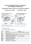
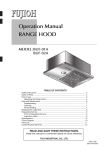
Contents
CONTENTS
Section
1.00
1.01
1.02
1.03
1.04
1.05
1.06
1.08
1.09
1.10
1.11
1.12
1.13
1.14
1.15
1.16
2.00
2.00
2.01
2.02
2.03
2.04
2.05
2.06
2.07
2.08
2.09
2.10
2.11
2.12
2.13
2.14
2.15
2.16
2.17
2.18
2.19
2.20
2.21
2.22
2.23
2.24
2.25
2.26
2.27
2.28
2.29
2.30
2.31
2.32
3.00
3.01
4.00
Page No.
Control Panel Installation
Introduction to Control Panel
Pre-installation Testing
Mounting Control Panel
Wiring and Safety Information
ST5500 Printed Circuit Board Wiring Terminals
ST5500 Control Panel Wiring Terminal Description
ST5500 Fuse Specifications
Wiring External Bell Boxes
Wiring Passive Infrared Detectors
Wiring System Tamper
Wiring Magnetic Contacts
Wiring K6600 Remote Keypad
Wiring SL6600 Sleep Watch Remote Keypad
Commissioning the System
Trouble Shooting
Engineer Installation Programming Section
Control Panel Factory Default Settings
Day Mode
Engineer/Installation Programming
Exit Time Adjustment
Entry Time Adjustment
Siren Duration Time Adjustment
Part Guard Exit Time Adjustment
Disable/Isolate Zones in Part Guard
Sleep Watch Delay Time Adjustment
Enable Sleep Watch Automatic Rearm
Sleep Watch Automatic Rearm Time Adjustment
Enable Sleep Watch Arm and Disarm Part Guard
Display Engineer Message on LCD
Display Zone Location Names on LCD
Miscellaneous Section 1
Enable Quick Set
Enable Special Switched Positive
Enable Exit Strobe Flashes
Enable Engineer Reset
Enable Engineer Burn In Code
Enable Push Button Final Set
Enable Day LED Illuminated Day Mode
Enable Entry Timed Out Full Alarm
Enable Switched Positive 0 Volts
Zone Type Description
Changing Full Guard Zone Type
Changing Part Guard Zone Type
Change Engineer Programming Code
Set System Date
Set System Time
Exit Engineer Installation Programming
Reset Control Panel to Factory Default Settings
Reset Control Panel without Losing Engineer Log
Engineer Reference Guide
Engineer Programming Record
Control Panel Technical Specifications
1
2
2
2
2
3
4
5
5
6
7
8
8
9
9
10
11
13
13
14
14
14
14
14
15
15
15
15
16
16
16
17
18
18
18
19
19
19
19
19
19
20
20
21
22
22
23
23
23
23
23
24
26
28
Contents
Contents
1.00
Control Panel Installation
1.01
Introduction to the Control Panel
Accessories and Low AC Low Voltage Cable Alarm Cable
Voltage Cables Entry
Knockout
The control panel has been designed for both installer and user friendliness. The factory default settings have
been carefully selected to suit most installation needs. However most functions are fully programmable for
flexibility when installing the system. All changes made are stored within a Non Volatile Memory (NVM) and are
retained even when there is complete loss of power.
Please read these instructions carefully before attempting to install this control panel. Ensure the user instructions are given to the user after installation.
1.02
220-240V
AC Mains
Cable Entry
Mains
Terminal Block
2. Remove the cover and put in a safe place with the screws. If connecting K6600LCD or SL6600
Sleepwatch remote keypad follow instructions as described within the keypad.
4. The control panel day LED will flash and also the mains LED will illuminate red indicating running from
battery power. The tamper LED will illuminate, indicating a tamper fault. Hold down the tamper spring
and fix under the on-broad keypad the tamper will extinguish.
Note: If LCD display indicates low battery, change the battery before proceeding with testing
the control panel.
5. Press:
PROG
6. Enter:
1
7. Press:
0
2
5
3
RESET
ST5500 BACK PLATE
1.04
ST5500 Transformer Wiring
Wiring and Safety Instructions
WARNING: ELECTRICITY CAN KILL
Ensure electricity is switched off at the mains before installing and
fitting the mains supply
Mains Power
Transformer
AC Plug Pack
Cable Entry
220-240V AC Mains
Cable Entry
Accessories and Low
Voltage Cables
4
Walk test (PA & Tamper give the same tone)
8. Remove and replace each zone link, the corresponding zone will be shown on the LCD display and
also beep indicating which zone is activated. After testing all the zones and tamper, release tamper
switch spring.
9. Press:
Red or Brown to L (Live)
Green/Yellow to Green E (Earth)
Blue or Black to N (neutral)
Internal
Speaker
Accessories and Low
Voltage Cables Entry
1. Release keypad cover and unscrew the two screws from the front cover.
Mains
Terminal
Block
Battery
Backup
Cables
twice, disconnect and remove the battery.
These simple tests will demonstrate that the control panel (and remote keypad if fitted) are working
correctly. Disconnect the battery from the control panel in preparation for wiring.
1.03
Internal
Speaker
Cable
Screw
Mounting
Hole
Pre-testing the Control Panel before Installing
3. Connect a fully charged 12V 1.2 Ah sealed lead acid battery, black lead wire to the negative (-) of the
battery terminal and the red lead wire to the positive (+) of the battery terminal.
220-240VAC
Mains Supply
Cable Connection
Battery Backup
Compartment
Zone
Links
Front Cover
Tamper Spring
AC Plug Pack
Wiring Terminal
ST5500
Mounting the Control Panel
The main control panel unit should be positioned out of reach of children in a secure place close to a mains
electricity supply. The unit should not be fitted to a flammable or uneven surface.
1. Remove the PCB by disconnecting the AC supply cable from the transformer and also from the speaker
connector, put the PCB in a safe place.
2. Using the rear panel as a template, mark the positions of the mounting holes. The mounting surface
must be solid. Do not fit to a flammable or uneven surface. Drill mounting holes and fit wall plugs.
3. Thread the mains supply AC power cable through the smaller aperture in the rear casing.
At this stage, do not connect the AC supply cable to the panel.
4. Attach rear panel to wall using at least three 30mm No.8 wood screws.
5. Replace the PCB and reconnect the AC and speaker connectors.
2
ST5500 Low Voltage
16.5V AC Plug Pack Wiring
1. The control panel must be wired according to Current National Wiring Regulations if fitted with an
internal transformer.
2. A readily accessible device for disconnecting from the mains (e.g. 3 amp un-switched fused spur)
must be provided as part of the installation.
3. If the control panel is wired to a 13 amp wall socket, a 3 amp 250V fuse must be used
4. Use mains 2 core cable and earth cable capable of carrying the rated current (i.e. at least 1mm²). The
control panel must be wired to earth.
5. Wiring of the mains supply to the transformer terminal block in the control panel should pass through
the smaller aperture in the rear casing of the panel, NEVER connect the mains supply directly to the PCB.
6. The unit requires wiring to a suitable earth, refer to National Wiring Regulations.
7. It is recommended that the unit is wired by a qualified electrician. Check for hidden cables and/or pipes
before drilling.
8. Use safety goggles when drilling or hammering in cable clips.
3
Contents
1.05
Contents
ST5500 Printed Circuit Board (PCB)
Key Switch
1.06
Battery Fuse
Auxiliary Fuse
250V 1.2A Fast Blow 250V 1.2A Fast Blow
AC Fuse
250V 1.2A Fast Blow
AC Power
Connector
NVM
Reset Pins
Speaker
Connector
PCB Terminals ST5500
Terminal
Description
Remarks
AUX 1 -
Regulated Auxiliary Supply Negative
AUX 1 +
Regulated Auxiliary Supply Positive
Maximum Output 250mA
SW +
Switched Positive Supply
Maximum Output 250mA
STB +
Latching Strobe Positive Supply
STB -
Latching Strobe Negative Supply
BELL +
Bell Positive Supply
BELL -
Bell Negative Supply
NETWORK B
Remote Keypad & Sleep Watch Data In
NETWORK Y
Remote Keypad & Sleep Watch Data Out
SAB 1 G/W
Self Contained Bell Output (SCB)
SAB 1 RT
Self Contained Bell Output (SCB)
TAMP
Tamper Alarm Zone Loop
Leave Link In If Not Used
Z1-Z4
Normally Closed Positive
Leave Link In If Zone Not Used
Leave Link In If Not Used
Fully Programmable Zone Loops
1.07
LCD Contrast
Adjustment
Fuses ST5500
Fuse
Description
Rating
AC
Power Supply Output Fuse
Fast Blow F1.2A, 250V, 20 X 5mm
AUX
Auxiliary Fuse
Fast Blow F1.2A, 250V, 20 X 5mm
BATT
Battery Fuse
Fast Blow F1.2A, 250V, 20 X 5mm
Zones 1-4 Links
Zone Expansion
Connector
Tamper Spring
4
5
Contents
1.09
Contents
Bell Box Wiring
1.10
Wiring Passive Infrared Detectors
Single Passive Infrared Detector
Consult Passive Infrared Detectors manufacturers installation
instructions before wiring to control panel.
If two or more Passive Infrared Detectors are wired to a
zone, wire power in parallel, wire alarm and tamper in series.
Use 6 core multi stranded cable .
Terminal
Connection
AUX 1 +
Detector Positive (12+)
White
AUX 1 -
Detector Negative (0V)
Green
Z1-Z4
NC
Black
Z1-Z4
C
Red
System Tamper
Tamper
Yellow
System Tamper
Tamper
Blue
4
6
7
Wire Colour
Contents
Contents
1.11
Wiring System Tamper
1.12
Wiring Magnetic Contacts
1.13
K6600 Wiring
1.14 Wiring SL6600 Sleep Watch Remote Keypad
8
9
Contents
Contents
Every effort has been made to provide accurate information, however slight variations can occur. We also
reserve the right to make changes for product improvement at anytime.
We recommend that you check your local by-laws relating to Intruder Alarm Systems. In certain
countries you are required by law to:
1. Notify the local police, in writing, within 24 hours of the alarm being installed, the names and
address of at least two key holders of the property protected.
2. Instruct the key holders in the operation and silencing of the alarm.
3. Within 48 hours of installation, inform the local Environmental Health Authority of the installation, and
which local police station you have notified.
4. Inform the local police of any changes of the key holders, within 24 hours of the change.
Option 1 Key Switch Wiring
Terminal
G
L
K
Connection
To Common –ve
To LED +ve
To Key Switch
Option 1 Key Switch Wiring
Wire Colou
Black
Red
Green
Terminal
G
L
K
Connection
To Push Button
Not Used
To Push Button
Wire Colou
Black
Red
Green
Note: Use only a non latching momentary key switch with an LED or push button with this
panel. The yellow LED operates exactly as the day LED on the control panel and therefore tells
you if the panel is armed or disarmed. You can only wire either a key switch option number 1
or push button final set option number 2 , which is the factory default setting. If using option
number 1, you must disable option 2 push button final set, in engineer programming under
section number 2.20.
1.16
Trouble Shooting
Always disconnect unit mains supply BEFORE removing the front cover
No
•
•
•
•
Mains Power to the Control Panel
Check the AC fuse on the PCB, if blown replace with 1.2Amp 250V fast blow fuse.
Check for loose wiring into the mains terminal block.
Check for loose wiring from mains supply.
Check AC connector is connected correctly to the control panel PCB.
No Battery Power to the Control Panel
• Check the Battery fuse on the PCB, if blown replace with 1.2Amp 250V fast blow fuse.
• Check Battery wires are connected correctly to the battery; Red +, Black -.
Note: If No Mains Power Supply and Low Battery this is Indicated on the LCD display.
1.15
Commissioning the System
Fit a fully charged 1.2Ah 12Vdc sealed lead acid rechargeable battery to the connectors inside the control
panel. After fitting the battery, the back LED will illuminate, Day LED will flash for a few seconds.
Replace the front cover of the main unit: tamper Fault goes off. Switch on the mains power, mains LED
illuminate on the main control panel and K6600 LCD remote keypad if fitted.
Go to USER manual page No.14 testing system and follow the instructions.
IMPORTANT
There are no user serviceable parts contained within the control panel and keypads.
DO NOT attempt to interfere with, or alter any of the electronic components. To do so may damage the
electronic circuitry and will invalidate your warranty.
The Epsilon-uk alarm system can provide valuable protection for your home and property if used properly.
However, the system can not guarantee complete protection against burglary or robbery. Therefore, the
manufacturer, distributor or supplier will not be held responsible for any loss or damage that may occur.
10
Unit Does Not Accept Code Upon Power Up
• If remote SL6600, K6600 LCD keypads are connected ensure each keypad has a different
address.
• Check wiring of remote keypads.
• Disconnect power momentarily so that the system can configure all keypads connected to system.
• Reset NVM to factory default settings.
Unit Will Not Set and Tamper Fault displayed on LCD.
• Check system tamper, replace link into tamper zone and replace lid to see if this clears the fault.
• Check system tamper wiring.
• Check tamper wiring to detector and sensors.
Unit Will Not Set Fault Zone displayed on LCD
• Ensure the zone is closed (No movement in that area, windows and doors are closed).
• Check wiring to that zone, replace link and see if system sets.
• Check wiring to detector and sensors.
• If you have a meter, check the resistance to that zone.
11
Contents
Contents
Day LED Flashing Fault displayed on LCD
• Enter USER code to set system note which zone is in fault
•. Ensure the zone is closed (No movement in that area, windows and doors are closed).
• Check wiring to that zone, replace link and see if system sets.
• Check wiring to detector and sensors.
• If you have a meter check the resistance to that zone.
2.00
Engineer Installation Programming Section
2.00
Control Panel Factory Default Settings
Tamper Fault
• Replace Tamper Link, press tamer spring if Tamper Fault clears,check wiring.
• Replace SAB Link, press tamer spring if Tamper Fault clears,check Bellbox wiring.
Unit Makes No Sound
• Ensure that the internal speaker is connected to PCB.
Remote Keypad Does Not Indicate Power
• Ensure you are using 6 core wire and that they are wired correctly to keypad and main unit.
• Check Power Fuse on Main Unit PCB, if blown replace with 1.2Amp 250V fast blow fuse.
External Bell Box Does Not Work
• Check wiring connections bell boxes on page 6.
Panic Button Does Not Work
• Ensure zone type is programmed as PA.
• Check wiring to control panel and panic button.
• Check panic button has been reset using the reset key.
Sleep Watch Keypad Does Not Work
• Ensure zones are programmed as Sleep Watch zones.
• Ensure each Sleep Watch Keypad has a different address to Remote Keypads or other Sleep
Watch Keypads.
• Check wiring to control panel and Sleep Watch Keypad.
• Check Power Fuse on Main Unit PCB, if blown replace with 1.2Amp 250V fast blow fuse.
12
Entry time
30 Seconds
Exit Time
30 Seconds
Alarm Time
15 Minutes
Part Guard Set Time
5 Seconds
Sleep Watch Zone Delay Activation Time
15 Seconds
Sleep Watch Zone Automatic Rearm Time
15 Minutes
Full Guard
Part Guard
Zone 1
Timed Entry/Exit
Timed Entry/Exit
Zone 2
Walk Through
Walk Through
Zone 3
Instant
Timed Entry/Exit
Zone 4
Instant
Instant
Zone/Tamper
Tamper
Tamper
Chime Zones
Clear
Date & Time
Clear
Day LED On
Enabled
Disabled/Isolated Zones
Clear
Double Knock Zones
Clear
Engineer Code
9 9 9 9
Engineer Code Burn In
Disabled
Engineer Service Timer
Disabled
Engineer Reset
Disabled
Entry Time Timed Out Alarm
Disabled
Final Set
Disabled
Fire Zones
Clear
Master User Code
1 2 3 4
Push Button Final Set
Enabled
Quick Set
Disabled
Secure Zones
Clear
Sleep Watch Zones
Clear
Sleep Watch Keypad Disarm Part Guard
Disabled
Strobe Exit Flashes
Disabled
Switched Positive
Normal
User Codes 2,3,4,5,6
Disabled
13
Contents
2.01
Contents
Day Mode
This is the normal (default) setting of the control panel. The alarm will only activate if the PA, Fire Zones or
Keypad PA are activated.
2.02
Engineer Installation Programming
Input a new Siren time (max. 255 minutes). Eg. for 10 minutes input 010, for 5
minutes input 005, etc. When the third digit is input, the panel will give an
acceptance tone and revert back to ENGINEER PROGRAMMING MODE.
Siren Time
015
Note: To comply with EN50301-1, siren time must be adjusted between
2 minutes (002) and a maximum duration of 1 5 minutes (015).
Engineer
Programming
To enter the engineer programming mode:
Press:
Enter:
Press:
Enter:
ST5500 & K6600
LCD Display
PROG
1
2
3
4
User
Programming
PROG
9
9
9
9
You are now in Engineer Programming.
Parameters can be adjusted as described in sections 2.03 to 2.30.
Engineer
Programming
Note: For user programming functions refer to engineer quick reference guide or user manual.
2.03
2.06
Part Guard set time is the maximum period of time between setting the alarm, and leaving the protected
area, this is pre-set at 5 seconds.
Part Guard Time
Press: 4
1
005
Input a new time (max. 255 seconds). Eg. for 10 seconds input 010, for 25
seconds input 025, etc. When the third digit is input the panel will give an
acceptance tone and revert back to ENGINEER PROGRAMMING MODE.
2.07
Exit Time Adjustment
Part Guard Exit Time Adjustment
Set Zones Disabled/Isolated in Part Guard
This is pre-set at 30 seconds. Exit time is the maximum period of time between setting the alarm, and
leaving the property via the EXIT route.
Exit Time
Press:
1
030
In this location enter zones to be Disabled/Isolated in part guard arming.
Input a new Exit time (max. 255 seconds). Eg. for 70 seconds input 070, for 95
seconds input 095, etc. When the third digit is input the panel will give an
acceptance tone and will revert back to ENGINEER PROGRAMMING MODE.
Press:
2.04
2.08
This is pre-set at 30 seconds. Entry time is the maximum period of time between activation (opening of
front door) of ENTRY/EXIT route and the alarm sounding. It will allow time to enter the property and switch
off the system.
Exit Time
Press:
2
030
Engineer
Programming
Note: To comply with EN50301-1 entry time should not exceed 45 seconds, alsointernal siren
activates if user code not entered before timing out, full alarm 30 seconds later.
2.05
4
Enter zone numbers to be omitted
To reset that zone, toggle the corresponding zone
Zones Disabled
None
Engineer
Programming
RESET
Set Sleep Watch Zone Delay Activation Time
In this location activation of a sleep watch zone will not activate a full alarm until after the zone delay
time has timed out, this is pre-set at 15 seconds.
S/W Delay Time
Press: 4
3
015
Input a new time (max. 255 seconds). Eg. for 10 seconds input 010, for 25
seconds input 025, etc. When the third digit is input the panel will give an
acceptance tone and revert back to ENGINEER PROGRAMMING MODE..
Engineer
Programming
Note: If a sleep watch zone is activated a valid user code must be entered to stop activation
sequence
2.09
Enable Sleep Watch Zones Automatic Rearm
In this location, after the user has pressed the sleep watch button to disarm sleep watch zones, they will
automatically rearm after the period of time programmed in location section 2.10 has timed out.
Siren Duration Time Adjustment
Press:
4
The Siren Duration time is pre-set to sound for 15 minutes, when activated. Do not set the alarm for a
longer period than that specified by legislation. You can adjust the siren to sound for less than 15 minutes.
Press:
2
Engineer
Programming
Entry Time Adjustment
Input a new Entry time (max. 255 seconds). Eg. for 45 seconds input 045, for
15 seconds input 015, etc. When the third digit is input the panel will give an
acceptance tone and will revert back to ENGINEER PROGRAMMING MODE.
Press:
Engineer
Programming
Press:
RESET
4
Sleep Watch automatic rearm enabled.
Toggle Key 4 to disable function.
and revert back to ENGINEER PROGRAMMING MODE.
3
14
15
S/W Rearm
Disabled
Engineer
Programming
Contents
2.10
Contents
Sleep Watch Zone Automatic Rearm Time
2.13
Each zone can be given a location name from the list below. The location name will be displayed upon the
ST5500 & K6600 remote LCD keypad display if that zone is activated or has a fault upon arming the system.
In this location, set sleep watch zones automatic rearm time, this is pre-set at 15 minutes.
Press:
4
5
S/W Rearm Time
015
Input a new time (max. 255 minutes). Eg. for 10 minutes input 010, for 25
minutes input 025, etc. When the third digit is input the panel will give an
acceptance tone and revert back to ENGINEER PROGRAMMING MODE.
Remote K6600 LCD Keypad Zone Location Display Names
Press:
4
8
Zone Name
Enter corresponding zone name number from list below
Engineer
Programming
Zone 1
Example: Zone 1 as Front Door enter 35
2.11
Enable Sleep Watch Arm and Disarm Part Guard
The Sleep Watch keypad can be programmed to arm and disarm part guard by pressing the
Sleep button for 3 seconds.
Press:
4
Press:
RESET
2.12
S/W Disarm
Enabled
Sleep Watch keypad disarm part guard enabled.
Toggle Key 6 to disable function.
6
Engineer
Programming
and revert back to ENGINEER PROGRAMMING MODE.
Set Installer Message
Enter the following options to display installer message on the ST5500 & K6600 remote LCD keypad when
in normal operation mode.
Press:
4
Message
7
16 characters can be programmed as the installer message. Enter the 2 digits to
represent the character required to be displayed on the LCD keypad. To move
the curser use the MEM key to move left and the OMIT key to move right.
Press:
RESET
00.
01.
02.
03.
04.
05.
06.
07.
08.
09.
10.
11.
12.
13.
When message is complete.
Space
(
)
*
,
–
.
/
0
1
2
3
4
5
14.
15.
16.
17.
18.
19.
20.
21.
22.
23.
24.
25.
26.
27.
6
7
8
9
A
8
C
D
E
F
G
H
I
J
28.
29.
30.
31.
32.
33.
34.
35.
36.
37.
38.
39.
40.
41.
16
K
L
M
N
O
P
Q
R
S
T
U
V
W
X
42.
43.
44.
45.
46.
47.
48.
49.
50.
51.
52.
53.
54.
55.
Y
Z
a
b
c
d
e
f
g
h
I
j
k
l
Engineer
Programming
56.
57.
58.
59.
60.
61.
62.
63.
64.
65.
66.
67.
68.
69.
m
n
o
p
q
r
s
t
u
v
w
x
y
z
Press:
1
Press:
3
5
Zone Name
Press:
RESET
Press:
RESET
01.
02.
03.
04.
05.
06.
07.
08.
09.
10.
11.
12.
13.
14.
15.
16.
17.
18.
19.
20.
21.
22.
23.
24.
25.
26.
27.
28.
29.
30.
Zone 1
Front Door
and revert back to ENGINEER PROGRAMMING MODE.
Alarm
Apartment
Auxiliary
Babies Room
Back Door
Back Yard
Barn
Basement
Bathroom
Bedroom 1
Bedroom 2
Bedroom 3
Bedroom 4
Boys Room
Building
Ceiling
Coatroom
Computer Room
Daughters Room
Desk
Dining Room
Dock
Downstairs
Driveway
East Room
Studio
Emergency
Entry & Exit
File
Fire
31.
32.
33.
34.
35.
36.
37.
38.
39.
40.
41.
42.
43.
44.
45.
46.
47.
48.
49.
50.
51.
52.
53.
54.
55.
56.
57.
58.
59.
60.
Floor
Foyer
Freezer
Fridge
Front Door
Gallery
Garage 1
Garage 2
Gas
Gate 1
Gate 2
Gymnasium
Guestroom
Hallway
Hold Up
House
Internal Door
Interior
Kitchen
Laundry
Library
Loading Area
Lock
Lounge Area
Maids Room
Master Bedroom
Medical
Mothers Room
Nursery
Office
17
Engineer
Programming
61.
62.
63.
64.
65.
66.
67.
68.
69.
70.
71.
72.
73.
74.
75.
76.
77.
78.
79.
80.
81.
82.
83.
84.
85.
86.
87.
88.
Outside
Panic
Patio
Perimeter
Police
Pool
Reception
Roof
Safe
Shed
Shop
Skylight
Sliding Door
Smoke Detector
Store Room
Sons Room
Studio
Study
Sun Room
Tamper
Utility
Vault
Ware House
Wash Room
West Room
Window
Work Shop
Yard
Contents
2.14
Contents
Miscellaneous Section 1
2.17
In this section under programming key 5 you can enable or disable any of the following features:
Section
Key No.
2.15
1
2.16
2
2.17
Zone LED
Factory Setting
Quick Set
1
Disabled
Special Switch Positive
2
Disabled
3
Exit Strobe Flashes
3
Disabled
2.18
4
Engineer Reset Any Alarm
4
Disabled
2.19
5
Engineer Code Burn In
5
Disabled
2.20
6
Final Set Push Button
6
Enabled
2.21
7
Day Mode LED illuminated
PA
Disabled
2.22
8
Entry Time Timed Out Alarm
Tamp
Disabled
2.23
9
Switch Positive 0 Volts
Day
Disabled
Press:
5
Description
if any features under this section have been enabled, displayed upon LCD.
Note: To enable or disable any of the above options, toggle the corresponding key number.
After entering options under this section press RESET to save changes and exit this location.
When this function is enabled upon setting the system in full guard the strobe will give 5 flashes indicating
system is set.
Strobe Flashes
Press: 3
Strobe Exit Flashes enabled..
Enabled
2.18
2.19
Enable Engineer Code Burn InS
When this function is enabled, the engineer code will be retained in the memory and can not be changed
even if the control panel is reset to factory default setting. In the event you forget your code PCB must be
returned to supplier for repair.
5
Code Burn In
Enabled
Engineer Code Burn In enabled.
Enable Quick Set
After enabling this option, the system maybe armed by pressing the set key for 3 seconds, this will
begin the full set arming sequence without entering a user code.
Quick Set
Press: 1
Quick Set enabled
Enabled
Note: If this function is enabled the installation will not comply with
EN50130-1 requirements.
2.16
Enable Engineer Reset
When this function is enabled upon setting the system in full guard the strobe will give 5 flashes indicating
system is set.
Engineer Reset
Press: 4
Engineer Reset enabled.
Enabled
Press:
2.15
Enable Exit Strobe Flashes
Enable Special Switched Positive
The programmable Switched Positive is a unique feature of this control panel. In the factory default, the
Switched Positive behaves in a normal manner (going high when the panel sets and low when the panel
is switched off) for latching passive infra-red detectors. In the Special Switched Positive, this output can
be used for impact sensors which require the power to be removed to reset them.
This output will give out up to 200mA as a positive supply to these detectors, which will behave in the
manner described below.
When enabled the Special Switched Positive will be high, but when the panel is switched on Switched
Positive goes low for 5 seconds, to reset the sensors. In the case of activation, even if the panel is reset,
the power will remain on the impact sensors until the panel is switched back on again. This enables the
information from the impact sensors to be retained.
Special Set Pos
Press: 2
Special Switched Positive enabled.
Enabled
18
2.20
Enable Final Set Push Button
The Final Set push button is used to Final Set the system after you have entered a code to arm the system
by pressing the button during exit time it will stop the exit timer and immediately arm the system. The button
should be installed on the outside of the protected area. During Day Mode and Part Guard it will act has a
door bell giving a chime sound when pressed. You can not use a key switch to arm and disarm system if
Final Set push button enabled.
F/S Push Button
Press: 6
Engineer Code Burn In Enabled.
Enabled
2.21
Enable Day LED
After enabling this option, the system Day LED will stay illuminated in Day Mode, when system is disarmed.
Press:
2.22
7
Engineer Code Burn In Enabled.
Day LED On
Enabled
Entry Time Full Alarm
After enabling this option, the system will go into full alarm, if the entry time times out before a valid
user code is entered.
Entry Alarm
Press: 8
Engineer Code Burn In Enabled.
Enabled
19
Contents
2.23
Contents
Switched Positive 0 Volts
After enabling this option, the Switched Positive will act in the following way. In armed mode and day mode
O Volts, any alarm activation 12 Volts. Enable this feature if using a Epsilon-uk AD1000 voice auto dialer.
Press:
9
Engineer Code Burn In Enabled.
Note: Special Switched Positive & Normal Switched Positive will not
work if this location is programmed.
Switched Pos 0V
Enabled
If you have enabled any of these options, Quick Set, Day LED or Entry Time Full Alarm the
system will not comply with current European alarm installation regulations.
After entering options under section 5, press RESET key to exit this location.
2.24
Zone Description
Final Set
If a Entry/Exit zone is programmed as final set, upon arming the system and leaving by the Entry/Exit route
the system will arm immediately once the Entry/Exit zone is clear without waiting for the exit timer to time
out.
Double Knock
When a zone is programmed as a Double Knock zone, it requires two activations within 30 seconds
before creating an alarm condition when panel is set.
Disabled/Isolated
When a zone is programmed has a Disabled/Isolated zone, it is ignored in the event of any activation. It
allows the user to continue using the alarm system even if a fault has been discovered on one or more
zones.
2.25
Exit
With the panel in DAY mode, if a valid user code is entered, the control panel will go into it’s armed
sequence. If any zone is at fault, the control panel will stop it’s count down until that zone is cleared or
omitted from the system, then will carry on arming the system.
Entry
When the panel is set and the entry zone is triggered, the entry timer will begin its countdown. During this
period, the remote keypad will give a repeated beep and will beep faster when nearly timed out. If the time
is allowed to elapse before any valid user code is entered, the control panel will go into alarm state. In this
case the system needs to be Reset by pressing the RESET key after a valid user code has been entered
to
disarm the system.
Walk Through
This zone allows access without the alarm activating provided that the exit/entry zone as been activated
before this zone.
Changing Full Guard Zone Type
All zones can be changed to any status listed below:
Key No.
Function
Zone LED
Factory Default
1
Timed Entry/Exit
Zone 1
2
Walk Through
Zone 2
3
Instant
Zone 3
4
Personal Alarm (PA)
Zone/PA
5
24 Hour (Tamper)
Zone/Tamper
6
Fire
Clear
7
Final Set
Clear
8
Double Knock
Clear
9
Zone Disable/Isolated
Clear
Instant
This zone will create an alarm condition immediately if the control panel is set.
Changing a zone status:
24 Hour/Tamper
A Tamper zone activation will only generate an internal alarm if the panel is in DAY mode. Triggering of the
tamper zone when the panel is set will always give an external as well as internal alarm
Enter zone number to be changed, the zone present status will be indicated on the LCD display
Press:
PROG
Personal Alarm (PA)
Triggering of the personal attack (P.A.) zone will always cause a full alarm regardless of whether or not
the panel is set.
Press:
RESET
Press:
6
Enter required key function number.
Press:
RESET
to return back to engineer programming.
Example: Programming zone 5 as Entry/Exit zone
Press:
6
Fire Zone
Triggering of the fire zone will operate internal & external sounders giving an intermittent sound, which is
easily distinguished from the normal alarm sound.
Press:
5
Press:
PROG
Note: Fire zones are intended as an extra feature to the alarm system and must not be regarded as a total fire protection system.
Press:
RESET
Zone 5
Instant
Press:
Zone 5
Entry/Exit
1
Engineer
Programming
To Change additional zones repeat these steps.
20
Zone Status
Full Guard
21
Contents
2.26
Contents
Changing Part Guard Zone Type
2.28
All Part Guard zones can be changed to any status listed below:
Key No.
Function
Zone LED
Setting System Date
In the event of an alarm activation, the date is stored in the memory log.
Factory Default
1
Timed Entry/Exit
Zone 1 & 3
2
Walk Through
Zone 2
3
Instant
Zone 4
4
Sleep Watch
Clear
Press:
9
Set Data
00-00-00
8
Enter date using 2 digits to represent Year, Month and Day. The year should be
entered first, followed by month and day, date will be displayed on LCD DD-MM-YY.
Note: If a zone is programmed as PA, 24hr, Fire or disabled in full guard it is not possible to change
the status in part guard.
After entering Day, it will revert back to engineer programming. To check date
entered, enter this location again, re-enter date if wrong.
Note:
Engineer
Programming
In the event of complete power failure, the Date & Time must be RESET.
Sleep Watch Zone
Sleep watch zones are like interior zones and can be armed and disarmed using the SL6600 sleep watch
keypad. Sleep Watch zones are armed in part guard after the system is set and by pressing the sleep Watch
button for 1 second. Upon a sleep watch zone being activated it will not instantly go into full alarm, but start a
delayed activation time has programmed. This gives the user time to disarm the system if a sleep watch zone
is activated accidentally by enter their code into the keypad.
In the event of an alarm activation, the time is stored in the memory log. The time is displayed in 24 hour
format.
Changing a zone status:
Press:
Press:
7
PROG
Press:
RESET
Enter required key function number.
Press:
RESET
Press:
7
Zone Status
Part Guard
Zone 4
Instant
4
Press:
PROG
Press:
RESET
Press:
4
Zone 4
Sleep Watch
To Change additional zones repeat steps B,C and D.
2.27
9
Set Time
00-00
9
After entering minutes, it will revert back to engineer programming. To check time
entered you must enter this location again, re-enter time if wrong.
Engineer
Programming
Changing Engineering Code
2.30
Exiting Engineer & User Programming
Press:
RESET
to exit engineer programming, Tamper LED on
Press:
RESET
to return to day mode, Day LED Flashing
2.31
Reset Control Panel to Factory Default Settings (NVM Reset)
To reset the NVM, power down the panel and short out the NVM pins, then power up and remove the
short. This will reset panel to factory set condition, If you have changed the installer message. this will be
retained in the keypad memory. If you wish to change the installer message the see section 2.12 for
instructions.
Changing a zone status:
Press:
8
Engineer
Programming
to return back to engineer programming.
Example: Programming zone 4 as Entry/Exit zone
Press:
Setting System Time
Enter time using 2 digits to represent Hours, Minutes, HH-MM
Enter zone number to be changed, the zone present status will be indicated on the LCD display
Press:
2.29
Enter New
Code
Type in new engineer code.
After entering the forth digit the panel will give an acceptance tone and return to
ENGINEER PROGRAMMING MODE, the new code will now be operative
From Engineer Programming mode
Press:
Engineer
Programming
22
2.32 Reset Control Panel without Losing Engineer Log
MEM
This will reset the panel to factory set conditions, but will not lose the engineers log.
23
Contents
Contents
3.00
Engineer Reference Guide
User Programming (PA, Tamper and Day LEDs On)
User Manual
Press: PROG
Press:
1234
Press:
0
Page
11
System Test Mode
14
Enter:
1
Strobe Test
Enter:
2
Bell Test
Enter:
3
High Sounder Internal Keypad
Enter:
4
Low Sounder Internal Keypad
Enter:
5
Walk Test (PA and Tamper Give Same Tone)
Enter:
0
Exit Test Mode
Press:
2
To Set Second User Code
Default : 0000
11
Press:
3
To Set Third User Code
Default : 0000
11
Press:
4
To Set Forth User Code
Default : 0000
11
Press:
5
To Set Fifth User Code
Default : 0000
11
Press:
6
To Set Sixth User Code
Default : 0000
12
Press:
7
To Set Secure Zones = Secure Zone LED Flashing
Press: RESET
12
Press:
8
To Set New Master User Code
Default: 1234
11
Press:
9
To Set Chime Zones (PA and Tamper LED illuminated)
Press: RESET
13
Press: RESET
Exit User Programming
Press:
Memory Recall Last Activation Shown First
Press: RESET
Engineer Programming
Installation Manual
MEM
13
Press: PROG
All Zone and Day LEDs illuminated
Press:
Master User Code Tamper and Day LEDs Stay illuminated
1234
9
Page
13
Default: 1234
Press: PROG
All Zone and Day LEDs illuminated
Press:
9999
Engineer Programming Code (PA and Day LEDs illuminated)
Default: 9999
Press:
1
Set Exit Time in Seconds
Default: 30 Seconds 14
Press:
2
Set Entry Time in Seconds
Default: 30 Seconds 14
Press:
3
Set Bell Rest Time in Minutes
Default: 15 Minutes
14
Press:
41
Set Part Guard Exit Time in Seconds
Default: 5 Seconds
15
Press:
42
Disable/Isolate Zones in Part Guard
Press: RESET
15
Press:
43
Set Sleep Watch Activation Zone Delay Time in Seconds
Default: 15 Seconds 15
Press:
44
Enable Sleep Watch Zones Automatic Rearm, Toggle Key 4
Press: RESET
15
Press:
45
Set Sleep Watch Zones Automatic Rearm Time
Default: 15 Minutes
15
Press:
46
Enable Sleep Watch to Arm/Disarm Part Guard Toggle Key 6
Press: RESET
16
Press:
47
Enter Installer Message Displayed on Remote LCD Keypad
Press: RESET
16
Press:
48
Enter Zone Description Displayed on Remote LCD Keypad
Press: RESET
16
Press:
5
Miscellaneous Section 1
Enter:
1
Enable User Quick Set
Toggle Key 1
18
Enter:
2
Enable Special Switched Positive
Toggle Key 2
18
Enter:
3
Enable Strobe Exit Flashes
Toggle Key 3
18
Enter:
4
Enable Engineer Reset
Toggle Key 4
18
Enter:
5
Enable Engineer Code Burn In
Toggle Key 5
18
Enter:
6
Enable Final Set Push Button
Toggle Key 6
18
24
Enter:
7
Enable LED Day Mode
Toggle Key 7
19
Enter:
8
Entry Zone Full Alarm
Toggle Key 8
19
Enter:
9
Switched Positive 0 Volts
Toggle Key 9
19
After Entering Options Press: RESET
Press:
6
Change Zone Status Full Guard: Enter Zone Number Press
Enter:
1
Timed Exit/Entry
Default: Zone 1
20
Enter:
2
Walk Through
Default: Zone 2
Enter:
3
Instant
Default: Zone 3-6
Enter:
4
Personal Alarm (PA)
Default: Zone PA/7
Enter:
5
24 Hour
Default: Zone Tamp
Enter:
6
Fire
Default: None
Enter:
7
Final Set
Default: None
Enter:
8
Double Knock
Default: None
Enter:
9
Disable/Isolate
Default: None
Press:
7
Change Zone Status Part Guard: Enter Zone Number Press
Enter:
1
Timed Exit/Entry
Default: Zone 1,3
Default: Zone 2
After Entering Option Press: RESET
21
Enter:
2
Walk Through
Enter:
3
Instant
Default: Zone 4,5,6
Enter:
4
Sleep Watch
Default: None
Press:
8
Set New Engineer Programming Code
Press:
9
Service Timer Section
After Entering Option Press: RESET
Enter:
1
No Service Timer
Enter:
2
6 Weeks Service Timer
Enter:
3
6 Months Service Timer
Enter:
4
12 Months Service Timer
Enter:
5
100 Events
Enter:
6
200 Events
Enter:
7
Default: 9999
21
22
800 Events
After Entering Option Press: RESET
Press:
98
Set Date
22
Press:
99
Set Time
22
Press:
MEM
Reset Panel To Factory Default Setting Without Losing
Engineer Log
23
Exit Engineer Programming
Press:
RESET Returns to User Programming
Press:
RESET Returns to Day Mode
Exit User Programming
Reset Panel to Factory Default Settings
Short NVM Reset Pins, Disconnect Power, Return Power To
The Unit and Remove Short From NVM Reset Pins.
25
23
Contents
3.01
Contents
Engineer Programming Record
Sleep Watch Zones
Function
Factory Settings
Zone 1
Clear
Entry Time
30 Seconds
Installation Settings
Zone 2
Clear
Exit Time
30 Seconds
Zone 3
Clear
Alarm Time
15 Minutes
Zone 4
Clear
Location
Full Guard
Zone 1
Timed Entry/Exit
Zone 2
Walk Through
Zone 3
Instant
Zone 4
Instant
Installation Company:
Fire Zones
Clear
Address:
Final Set Zones
Clear
Address:
Double Knock Zones
Clear
Disabled/Isolated Zones
Clear
Sleep Watch Zones Delay Activation Time
15 Seconds
Date of Installation:
Sleep Watch Zones Automatic Rearm
Disabled
Maintenance & Call Out Record
Sleep Watch Zones Automatic Rearm Time
15 Minutes
Maintenance & Call
Sleep Watch Keypad Arm/Disarm Part Guard Arming
Disabled
Installer Message
Epsilon-uk
Quick Set
Disabled
Special Switched Positive
Disabled
Exit Strobe Flashes
Disabled
Engineer Reset
Disabled
Engineer Code Burn In
Disabled
Final Set Push Button
Enabled
LED Day Mode Illuminated
Enabled
Entry Timed Out Full Alarm
Disabled
Switched Positive O Volts Day & Armed Mode
Disabled
Date
Clear
Time
Clear
Set Time
5 Seconds
Zones Disabled/Isolated
None
Zone 1
Timed Entry/Exit
3.02
Customer Information
Installation Engineer:
Telephone Number:
Date/Time
Reason For Visit
Name of Engineer
Part Guard
Zone 2
Walk Through
Zone 3
Timed Entry/ExitInstant
Zone 4
Instant
26
Note:
These instructions MUST NOT be stored inside the control panel
The User instructions contain ESSENTIAL SAFETY INFORMATION & MUST be given to the user.
27
4.00
Electrical and Technical Specifications
Power Supply
Primary Mains Supply Voltage Rating:
Secondary Input Voltage Rating:
Maximum Total Current Rating:
Rechargeable Backup Battery:
230Vac/115Vac (E10%)
16.5Vac
900mA
12V Sealed Lead Acid 1.2 Ah
Environmental
Operating Temperature:
Storage Temperature:
Maximum Humidity:
EMC Environment:
-10oC (14oF) to 50oC (122oF)
-20oC (-4oF) to 60oC (140oF)
95% non-condensing
Residential/Commercial
Electrical
Current Consumption:
Quiescent Current:
Alarm Current:
Auxiliary Voltage Output:
Switched Positive Voltage:
When Low:
When High:
Bell Voltage Output:
Speaker Voltage Output:
Strobe Voltage Output:
Internal Sounder:
Positive Loop Threshold (Zones 1-4):
Minimum Open Resistance:
Maximum Closed Resistance:
Negative Loop Threshold (System Tamper):
Minimum Open Resistance:
Maximum Closed Resistance:
<90mA
<240mA
Regulated 12.5Vdc
1.0Vdc
12Vdc
12Vdc
12Vdc
12Vdc
0.50Watts 32 Ohms
70kΩ
10kΩ
110kΩ
20kΩ
Physical
Dimensions:
Housing Material ST5500:
Weight ST5500:
260mm X 225mm X 80mm
Inflammable 94VO High Impact ABS Plastic
1.30Kgs
K6600 Remote LCD Keypad
Electrical:
Operating Voltage:
Quiescent Current LCD Back Light Off:
Current LCD Back Light On:
Current in Alarm
Wiring:
Dimensions :
Housing Material:
Weight:
12Vdc
16.7mV
90mA
70mA
6 Core Multi-stranded Cable 7 x 0.20m2
135mm X 108mm X 80mm
ABS Plastic
0.30Kgs
SL6600 Sleep Watch Remote Keypad
Electrical:
Operating Voltage:
Quiescent Current :
Wiring:
Dimensions :
Housing Material:
Weight:
12Vdc
16.7mV
4 Core Multi-stranded Cable 7 x 0.20m2
135mm X 108mm X 80mm
ABS Plastic
0.20Kgs
28