1
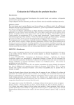
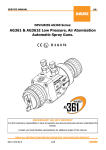
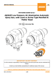
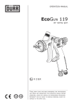
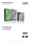
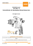
TM
Operating Instructions
TM
TM
for RubbaFIX MELTA Pro
www.rubbafix.com.au
Australia (Toll Free): 1800 352 228
International: +61 2 8853 3000
Operating Instructions
•
•
•
•
•
•
•
Fill the tank with the required amount of repair compound.
Turn Main Power “ON”.
When the Pump Ready light is on, the system will be up to temperature.
Turn the Pump Switch “ON”.
Allow approximately 15 minutes of additional warm-up time.
The pump is activated by the trigger switch located on the gun.
The flow control can be adjusted using the Flow Control Knob located on the rear right side of the system.
RubbaFIX™ MELTA™ Pro
The RubbaFIX MELTA™ Pro is designed for the application of adhesive in operations requiring dispersion of the
repair compound over large surface areas or in other situations where the RubbaFIX™ MELTA™ Mini is not of size.
The repair compound flow is controlled by using an air regulator and solenoid which delivers atomising air under
pressure through an air line integrated with the heated hose to a flow nozzle attached to the gun. The flow pattern
can be varied by the following:
1. Increasing or decreasing the air flow by adjusting the air pressure on the Flow Pattern Regulator.
• Turn clockwise to increase
• Turn counter-clockwise to decrease
2. Increasing the repair compound flow by adjusting the Flow Control Knob.
• Turn clockwise to increase
• Turn counter-clockwise to decrease
3. Changing the guns Fluid Nozzle can vary the flow pattern.
• Available Fluid Nozzles: 0.060” orifice 0.040” orifice
Figure 1: Flow Control Knob
WARNING: Do not adjust flow control
before machine has reached
operating temperature.
See our full range online at www.rubbafix.com.au
There is a direct relationship
between the glue pressure and
the air pressure.
Control Panel Settings
Set Temperatures:
Press and hold the Zone button (Tank, Hose or Gun)
for 2 seconds. When the Set Mode light illuminates,
continue to hold and adjust the set temperature up
or down using the arrow keys.
Figure 2: Control Panel
Set temperatures cannot be adjusted when the Set
Lock is activated. Set temperatures range from
38°C – 204°C (100°F – 400°F), in 5°F increments.
Ideal Temperatures:
Optimal product temperature is 190°C. To achieve
this, the Tank temperature needs to be set between 160°C – 170°C, the Hose temperature at 180°C and the Gun
temperature at 200°C.
In a cold environment the temperature may need to be adjusted higher to achieve the ideal product temperature.
The belt may also need to be preheated using a hot air gun to maximise product adhesion.
Actual Temperature:
During operation, actual temperatures scan every five (5) seconds. To read the actual temperature of any zone, press
the Zone button and the actual temperature will be displayed.
Standby:
Press the Standby Button to lower the set temperature in each zone by 50%. While in Standby, the pump will not operate.
Pump Ready:
The pump will operate when the actual tank temperature is within -4°C (25°F) of the set temperature. The pump will
not operate if the system is in Standby or if the actual tank temperature drops -4°C (25°F) from the set temperature.
Over Temperature Protection:
If any zone reaches 218°C (425°F), the Over Temp light will illuminate and the system will shut off. The Temperature
Display will read “OFF” and the light adjacent to the faulted zone will flash red.
Set Lock:
The Dip Switch on the back of the front panel can be set to lock the set temperatures.
°F Vs.°C:
The Dip Switch on the back of the panel can be used to display °F or °C.
Basic Electrical Power Connections
•
•
•
A reliable 208-240 VAC is required. Heater efficiency will drop with voltages less than 220 VAC.
Severe performance problems will occur with voltage less than 208 VAC or greater than 240 VAC.
Total amp draw will depend on the final system configuration.
Do not allow the system to share the same circuit with other electrical items.
Figure 3: Basic Electrical Power Connections
G
N
D
GROUND
L2 (Y)
L1 (X)
220V
L2
L1
Main Power
Breaker
L1 L1 L2 L2
The RubbaFIX™ MELTA™ Pro can cause severe injury if incorrectly used. Those who use and maintain the system
should be trained on its proper use, warned of its dangers and should read the entire manual before attempting to
set up, operate or adjust the machine.
TM
CAUTION
•
•
•
•
•
•
Do not squeeze the trigger switch on the gun when the system is cold.
Do not adjust the Flow Control Knob when the system is cold.
Do not allow the pump motor to stall. A prolonged stall will cause the motor to go into thermal overload.
Do not connect or disconnect electrical connectors or remove components with the power on.
This will prevent arcing of electrical contacts and possible failure of components.
Always close and secure the control panel access cover to protect internal electrical components.
Always operate the system with the tank lid on.
WARNING
•
•
•
•
•
•
Working on or around the RubbaFIX™ MELTA™ Pro and equipment can cause severe burns.
Use eye protection, gloves and protective clothing while operating.
Before using any RubbaFIX™ MELTA™ Pro equipment, determine proper electrical requirements as per all
applicable codes.
At RubbaFIX™ Pty Ltd, we pay special attention to the needs of operators and service personnel when designing
equipment, but molten repair compounds are dangerous and can cause severe burns. Extreme care must be
exercised to insure personnel safety.
Ensure hazardous material(s) that are toxic, heat or fire sensitive are not located in the immediate vicinity of the
RubbaFIX™ MELTA™ Pro as fire, explosion, personal injury, property and/or equipment damage can result.
The RubbaFIX™ MELTA™ Pro system is equipped with over temperature protection as a necessary safety device.
Run-away heating can cause hot melt materials to exceed their flash point.
RCM Compliance
This is to certify that the above applicator in the design marketed is in conformity with the following EMC guidelines:
AS/NZS 61000.6.3: 2012
E1839
Australia (Toll Free): 1800 352 228
International: +61 2 8853 3000
See our full range online at www.rubbafix.com.au
TM
TM
For further information on how RubbaFIXTM solutions can help you with
your next project, please contact our head office or visit rubbafix.com.au
Head Office:
Unit 7, 6 Gladstone Road
Castle Hill, NSW 2154
Australia
Mail To:
PO Box 6467
Baulkham Hills BC, NSW 2153
Australia
Contact:
Australia (Toll Free): 1800 352 228
International: +61 2 8853 3000
Fax: +61 2 9634 7145
Email: info@rubbafix.com.au