1
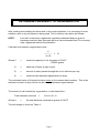
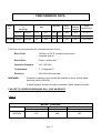
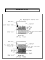
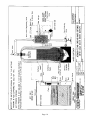
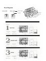
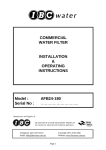
COMMERCIAL
WATER SOFTENER
INSTALLATION
&
OPERATING
INSTRUCTIONS
Model :
Serial No :
AS30400
………………………..
Manufacturer and Supplier of
FILTRATION & WATER TREATMENT PRODUCTS
for commercial, industrial and residential application
Telephone: (07) 3219 2233
Email: [email protected]
Facsimile: (07) 3219 2266
Website: www.ibcwater.com.au
Page 1
INSTALLATION
Check the equipment upon arrival for damage or shortages and report same to our Office or
Agent before commencing installation.
Locate the unit and brine tank on a firm level clean foundation, preferably concrete, with
sufficient space for operation and maintenance. Position the tanks in their correct position
before loading the media.
MEDIA INSTALLATION
Step 1:
Remove the top tank flange/strainer assembly by unscrewing out the larger
diameter flange and make sure the softener tank is empty and clean. It is
recommended to utilise special ‘C’ type spanners available from I.B.C.
Step 2:
Bottom distributor assembly is pre-assembled and installed in the Softener Tank.
Step 3:
Place a 40mm or 50mm plastic pipe through the top hand hole that will reach to
the bottom of the softener tank. Carefully pour the underbed gravel through this
pipe so as not to damage the distributor assembly.
Step 4:
Pour in the underbed gravel (No.6) evenly around the tank, 120kg.
Step 5:
Level out the underbed gravel using a broom handle/PVC pipe. The underbed
gravel should cover the bottom distributor by about 25mm.
Step 6:
Fill the tank with water to about 1/2 full of water.
Step 7:
Load the 400 litres of C100E resin. The resin is shipped in 25L bags.
Step 8:
Completely fill the tank with water.
Step 9:
Clean top of tank of all traces of resin.
Step 10: Unpack the valve and pipe work, check that each union has its ‘O’ ring.
Page 2
Step 11: Replace top tank/flange/strainer assembly (removed in Step 1) and tighten. Fit
pipe work supplied and hand tighten each union. Check that main valve and pipe
work is vertical, tighten all unions. Fit air release valve to the Tee at the top of the
pipe work. Check all joints and flanges are tight. Do not overtighten.
Step 12: Remove the lid of the brine tank and remove the brine tube (black poly flexible
tubing). Connect the brine tube to the throttle/stop valve on the main control
valve.
Step 13: Remove the brine valve from the brine well of the brine tank. Ensure brine tank is
free from foreign matter and set brine valve and float height as follows:Determine if wet salt or dry salt is required, using the formula
shown in “Determining Frequency of Regeneration”. If sufficient
information is not available to do the calculations shown in
“Determining Frequency of Regeneration”, contact our office. The
brine valve is supplied factory fitted with a dry salt riser, a wet salt
riser is also supplied (short black screwed riser pipe - refer Fig.
19). Store the riser tube not used, DO NOT DISCARD it may be
needed at commissioning.
Step 14: Replace the brine valve in the brine well and connect brine tube - this tube is
supplied long and can be cut to the desired length.
Step 15: Now add the No 4 gravel to the brine tank (120kg - 6 bags) and level. Ensure no
gravel enters brine well - add salt to the tank (refer Table 7 for correct quantity),
replace lid.
Step 16: Plumb the unit, noting the following:a)
Check arrow markings on the valve for correct inlet/outlet plumbing (Fig.1).
b)
Use minimum 50mm pipe size.
c)
Fit a pipe union to drain line for ease of access for maintenance or cleaning.
d)
Install inlet and outlet isolating valves and a Manual Bypass Valve (if
desired).
e)
Install optional water meter if required.
f)
Connecting pipe work and valves MUST be supported to prevent loading on
the valve and pipe work. Before connecting pipe work, flush all lines, close
inlet, outlet and bypass valve.
Page 3
g)
The drain line must discharge into an open pipe at least 80mm diameter no
more than 3 metres from the unit. An air gap of 100mm should be allowed
for inspection and to conform to sanitary codes. Connect the 172 Valve
actuator drain line to the waste with 10mm tubing.
h)
Power supply is required not more than 0.5 metres from the unit and should
be a 3 pin 10a 240v 50Hz GPO preferably earth leakage protect.
Total power draw, 13 watts maximum.
i)
Minimum operating pressure 205 kPa (30psi), maximum operating pressure
690 kPa (100psi). If supply pressure is above 690 kPa, fit pressure reducing
valve. This must be a non-fluctuating supply. Maximum temperature of 58°C
j)
Slowly fill Softener Tank with water by placing control valve in backwash
position, turn off inlet isolating valve when tank fully vented of air. Refer to
start up procedure Page 4, of 172 Valve Installation, Operation &
Maintenance Manual.
Page 4
DETERMINE FREQUENCY OF REGENERATION
After locating and installing the brine tank in the required position, it is necessary to know
whether a wet or dry salt system is being used. This is done by calculation as follows:NOTE:
Less salt is required to regenerate a partially exhausted bed per gram of
hardness removed, than that required for a more exhausted bed. For economy
sake, regenerate before full exhaustion.
Calculate time between regenerations thus:C
----------HxQ
=
N
Where C
=
maximum capacity of unit as grams of CaCO3
= 28000 grams.
H
=
hardness of water a mg/l or ppm.
Q
=
amount of water passed through the unit in kilolitres per day.
N
=
maximum time between regenerations in days.
The calculated value of N should be taken down to the nearest whole number. This is the
maximum number of days, which can be achieved between regenerations.
The amount of salt needed per regeneration, is calculated thus:Total hardness removed
Where A
=
=
NxHxQ=A
the total hardness removed as grams of CaCO3
The salt dosage is found on Table 4.
Page 5
EXAMPLE
Unit AS30400
Litres of resin “400” from Table 4
Hardness of water 90 mg/l
Flow 15kl/hr for 18 hours /day.
Q
=
15 x 18
=
270 kl/day
H
=
90 mg/l or ppm
C
=
24300 grams (= 270 x 90)
Frequency of regeneration -
N
=
C
------------HxQ
=
24300
------------90 x 270
=
1.0 day
Always go down to the nearest whole number (say 1 day).
Total hardness removed A
=
=
=
NxHxQ
1 x 90 x 270
24300 grams
The medium and maximum capacities of a single unit from Table 4 are 21000 and 28000
respectively. The calculated capacity falls closer to the maximum and so the higher value
should be used.
Salt dosage required per single softener for 28000 g is 96 kg (from Table 4).
Now looking at Table 5 we find that only wet salt can be used. However, if your calculated
salt dosage allows you the choice of either dry or wet salt always choose dry salt.
In the case of the example the salt dosage is 96 kg so the float setting is 350mm (refer Brine
Tank Set-up for float setting details), brine tank size is 1070 x 1220.
Install the brine valve as shown in Brine Tank Set-up.
The initial salt load as shown in Table 7 should be loaded into the brine tank.
Page 6
IMPORTANT NOTE:
The water softener, as supplied, has the brine riser pipe assembled to suit dry salt
brine system. If, however, on reference to Table 5 you find that wet salt must be
used, then wet salt brine rise pipe (short black pipe piece supplied) must be fitted to
the brine valve.
Note: For wet salt it is very important that the salt level be maintained in line with the
brine valve. As illustrated in the brine tank setup sheet, the salt used per
regeneration must be replenished at least 4 hours before the next regeneration.
Page 7
COMMISSIONING
Step 1:
Check plug is dry first, then connect lead into power outlet and switch on. Check
that the brine throttle/stop valve is closed.
Step 2:
Fully open the control valve electrical cabinet cover and hold in this position with
a temporary tie cord. Depress the red knob (Fig. 5) and rotate anti-clockwise to
backwash position, release red knob, wait for valve drive to index to backwash
position. (if not already in this position).
Depress red knob and rotate anti-clockwise to brine position, release, wait for
valve drive to index to brine position. Depress red knob and rotate to brine refill
purge position and release.
Step 3:
Just open inlet isolating valve approximately 1.1/2 turns. Allow unit to fill slowly
(water will issue to drain) continue to run until the unit automatically indexes to
Service position which may take up to 10 minutes. All air must be removed.
Step 4:
Open brine throttle/stop valve approximately 1.1/2 turns, fully open inlet isolating
valve. Open the cold water isolating valve and allow brine tank to fill until brine
float valve shuts off. A period of four (4) hours soaking should elapse after filling
with water before commissioning to allow the brine to saturate. Depress the red
knob and turn anti-clockwise to start, release, the unit will now go through each
cycle - Backwash, brine rinse, purge and back to service automatically, the full
cycle will take approximately 90 minutes.
NOTE: A small amount of media may pass to drain during the initial backwash,
this is considered normal. When unit commences brine and rinse cycle, adjust
brine throttle/stop valve to the correct draw down rate.
The draw down rate is determined by dividing the float setting height, selected
from Table 5, by 20. eg if 300mm is the float height selected, the draw down rate
is 15mm per minute. Draw down is measured with a tape measure in the brine
well, and is the distance in ‘mm’ that the brine level drops in one minute.
Step 5:
Check with site supervisor that unit can go on line. If so - slowly open outlet
isolating valve fully, check that manual bypass valve is fully closed. This unit is
now on line.
Step 6:
Check for and report any leaks. Go to nearest tap, now on soft water, open and
allow to flow for a few minutes. Using test kit to test for soft water - refer testing in
back of these instructions. It may take several minutes for the soft water to pass
to the tap. If hard water persists refer to the Service hints in these instructions.
Check that the brine tank is full and that the float has shut off.
Page 8
Step 7:
In the calculations you have done (determining regeneration frequency) you
found the value for (N) - maximum time between regeneration in days. To set the
skipper wheel up as required, pull all the skipper wheel pins (Fig. 5) out.
Turn the dial to the correct day of the week on which you are setting the dial. Now
depress the pins for the desired day/s for regeneration/s required. If no data is
available to do the calculations at this stage then set regeneration for every
second day.
When setting the regeneration frequency you should take into account the
working days, for instance if the installation will only work week days,
regeneration on Friday and Monday would be a needless waste of salt. Always
set in accordance with the duty conditions for maximum economy.
NOTE: This is only a guide for initial setting and should be altered to suit each individual
installation in accordance with load conditions - do the calculations in determining
frequency of regeneration, it will help you in understanding the softener.
Step 8:
Set time of day, pull timer knob (Fig. 5) and set arrow to the time of day (time of
your watch) release, make sure that the knob has re-engaged gear, knob right in.
Step 9:
Replace the timer cover, wipe over unit.
Do final check for leaks etc.
Page 9
HARDNESS TEST
1.
Water to be tested should be taken from a tap after the water softener
2.
Measure 10ml of water into plastic bottle supplied (approximately 1/3 full)
3.
Add one Yes/No tablet to sample water, replace cap and shake until tablet
has completely dissolved.
(NOTE: do not handle Yes/No tablet with fingers)
4.
The final colour to be obtained for soft water is green. (Note: The shade of
green may vary.) If the colour turns red, the water is above 20mg/l hardness,
therefore another regeneration is recommended.
5.
Rinse plastic bottle after each test has been completed.
6.
When used as above, the tablets change the colour from green to red at a
hardness of approximately 20ppm based on a sample volume of 10mls.
Other hardness test kits are available for more accurate testing eg.
Hardness Tablets
Directions:
Take a 50ml sample of water in a screw capped bottle. Add one (1)
tablet to sample, shake or crush to disintegrate. Repeat until last trace
of reddish tinge disappears. The final colour is usually blue but with
some water a greyish coloured end point is obtained.
Using 50ml sample Hardness ppm = (number of tablets x 40) - 20
LR (BW) Tablets
Directions:
Take a 100ml sample of water in a screw capped bottle. Add one (1)
tablet to sample, shake or crush to disintegrate. Repeat until last trace
of reddish tinge disappears. The final colour is usually blue but with
some water a greyish coloured end point is obtained.
Using 100ml sample Hardness ppm = (number tablets x 2) - 1
Contact IBC Water Treatment if further details are required.
Page 10
PERFORMANCE DATA
Capacity
&
Salt Dosage
Model
No.
AS30400
Service Flow
Rate
Pipe Size
Minimum
Maximum
Peak
Flow
Continuous
Flow
Inlet
Outlet
Drain
grams/kg
grams/kg
l/m
l/m
mm
mm
14000/26
28000/96
350
265
50
40
Resin
Volume
Approx.
Shipping
Weight
Space
Requirements
Litres
wt/kg
W xDxH
metres
400
830
1.8x1.2x2.6
Peak flow not recommended for extended periods of time.
Brine Tank:
1000 litre L.D.P.E. moulded construction
complete with lid.
Brine Valve:
Plastic construction.
Operation Pressure:
210 - 600 kPa
Temperature:
5 - 50 degrees C
Electrical:
240v 50Hz 3w maximum
WARNING:
A pressure reduction valve should be installed in areas of high water
pressure (above 690 kPa).
A water hammer arrester should be installed if water hammer prevails.
FAILURE TO OBSERVE WARNINGS WILL VOID WARRANTY
Table 3
MEDIA LOADING
Model
Underbed Gravel No.6
kg
Resin Content
litres
Brine Tank Gravel No.4
kg
AS30400
120
400
120
Page 11
Table 4
Grams capacity and salt dosage - grams as CaCO3 / salt kg
Model
AS30400
Resin
Minimum
Medium
Maximum
litres
grams/kg
grams/kg
grams/kg
400
14000/26
21000/53
28000/96
Table 5
Float settings (mm)
Salt Dosage
(kg)
Brine Tank Size
1070 x 1220
Dry
270
335
420
460
545
625
670
-
32
40
50
55
65
75
80
90
95
110
120
Wet
110
135
170
185
215
250
270
300
320
370
405
Table 6
Specification flow rate - lpm - nominal only.
Model
Backwash
Brine
Slow Rinse
Fast Rinse
AS30400
95
33
25
95
Table 7
Model
AS30400
Initial Salt Loading - Kgs
Dry
Wet
800
Page 12
275
BRINE TANK SETUP
Page 13
Page 14
Series 172
Commercial / Industrial
Control System
Water Softener
Page 15
START-UP PROCEDURE
Includes procedures to pressurise softener tank
and fill brine tank
With all piping and installation completed, and with
mineral in the tank, proceed as follows:
1. Disconnect electrical power to timer.
2. Remove valve cover to expose timer and
mechanism.
3. Open manual bypass valve, close manual inlet
and outlet valves (see Figure 2).
4. Push in on RED KNOB on timer, turn counterclockwise until arrow on the camshaft/timer
support points to the BACK-WASH position
indicated on #1 cam (see Figure 5).
9. Fill the brine tank with the proper amount and
type of salt recommended for the use with the
system.
10. Push in RED KNOB and index pilot valve to
PURGE. Allow water to flow to drain until clear.
During this time the brine tank will fill until the
float closes the brine tank valve. Check that all
the brine fittings are tight and that water level in
brine tank os according to softener
specifications.
11. Index the valve to SERVICE.
12. Close manual by-pass valve and open outlet
valve fully.
Figure 6
Figure 5
Set Timer
5. Slowly open manual inlet supply valve. DO NOT
open fully. Water will enter from the bottom of
filter tank as air is expelled from the top to the
drain. Full flow of water could cause loss of
media. Continue to fill slowly until air is expelled
and only water flows to drain.
NOTE: If top cover of softener tank can be removed
to vent air, the tank may be filled more quickly.
Observe the level and replace cover before tank
overflows.
6. When ONLY water flows to drain, open inlet
valve fully and backwash until water looks clean
when caught in a container.
7. Push in RED KNOB and index timer counterclockwise to BRINE/RINSE position (arrow on
camshaft/timer support pointing to BRINE/
RINSE on #1 cam). Observe a slow flow of
water to the drain.
8. Push in RED KNOB and index timer to
PRESSUR. (pressurise) position indicated on #1
cam (see Figure 6). Keep in this position for 5
minutes. This allows the tank to return to line
pressure and permits easier movement of the
valve discs.
Determine a regeneration schedule for the softener
and adjust the automatic timer (see Figure 9) as
follows:
1. Put all SKIPPER PINS up (away from control).
2. Rotate SKIPPER WHEEL until DAY ARROW
points to day of week.
3. Depress SKIPPER PIN(S) for day(S)
regeneration is required.
4. Pull TIMER KNOB out (away from timer face)
and rotate until BLACK ARROW on tripper arm
points to correct time of day on Face Plate.
5. Timer will automatically initiate backwash on
preset days at 2:30 A.M. To alter time, simply
reset TIMER KNOB to an earlier or later time
which will change the time of regeneration by
the same number of hours. (Time indicated at
BLACK ARROW will no longer be correct).
Set BACKWASH timing (Figure 7)
Make sure time is in the SERVICE position. Loosen
the screw (A) on the white gear (B) and rotate the
grey gear (C) with the numbered decal until desired
Page 16
time (3, 6, 9, 12, 15, 27 minutes) aligns with pointer
on box (D). Tighten the screw on the white gear.
(pressurise) position pause for at least 5
minutes or until tank is pressurised.
Final check-out
1. Test for soft water from a convenient soft water
tap.
2. Manual by-pass valve must be closed (see
Figure 2).
3. Manual inlet and outlet valves open (see Figure
2).
4. Brine line shut-off valve open (see Figure 4)
5. Drain line clear and unobstructed.
6. Electrical power to timer (not controlled by
switch).
7. Time of day, frequency of regeneration,
backwash timer and brine/rinse time set
properly.
8. Proper liquid level in the brine tank and supply
of salt.
Figure 7
Set PURGE timing (Figure 8)
Make sure timer is in the SERVICE position. Loosen
the screw (E) on the grey gear (F) with the pointer
until the pointer aligns with the desired time (5-35
minutes). Tighten the screw.
Figure 9
Figure 8
MANUAL OPERATION
A. Start-Up or inspection regeneration.
B. Manual initiation of regeneration.
1. Disconnect electrical power.
1. Reconnect electrical power.
2. Push the RED KNOB and turn counterclockwise past START to BACKWASH.
Leave in position for desired time.
2. Push in RED KNOB and turn counterclockwise to the START position. Release.
Unit will then go through a complete
regeneration as programmed.
3. Push in RED KNOB and repeat for all
desired cycles. NOTE: At PRESSUR.
Page 17
Flow Diagrams
PUSH/PULL ROD
6 OUTLET
VALVE DISC
5 BY-PASS
4 DRAIN
3 BACKWASH
3 BACKWASH
VALVE CLOSED
VALVE OPEN
1 INLET
Page 18
2 BRINE
Page 19
Page 20
Figure 10
Figure 11
Three pressure taps are available on the Pilot Valve for
use in actuating external diaphragm valves.
Pressure TAP No. 2 will give a pressure signal during
SERVICE, BRINE, RINSE, PURGE and BRINE REFILL
cycles; pressure TAP No. 3 will give a pressure signal
during BACKWASH cycle; and pressure TAP No. 7 will
give a pressure signal throughout the entire
REGENERATION cycle.
Before attaching a ¼ " (6.2 mm) tube to any pressure
tap, drill out the barrier in the tap using a ⅛" (3.1 mm)
drill. Use a ¼ " (6.2 mm) plastic ferrule nut to make the
connection. Insert the drill into the opening of the tap and
drill the hole in the barrier being careful not drill through
the backwall of the tap.
Page 21
GENERAL SPECIFICATIONS
Figure 15
Hydrostatic test pressure ……………………………………………………………………………………………. 250 psi (17.2
bar)
Working pressure ……………………………………………………………………………………….. 20 - 100 psi (1.38 - 6.89
bar)
Standard electrical rating …………………………………………………………………………………………………….
120V/60Hz
Optional standard electrical rating (Timers) ………………………………..……… 24V/50Hz, 120V/50Hz, 24V/60Hz,
24V/50Hz Electrical cord (when furnished …………………….………………………………………………….. 6" (150 cm), 3
wire with plug
Electrical Connection ………………………………………………………… 1/2" (1.3 cm) conduit opening. Terminal strip
inside
Standard plumbing connection …………………..……………… 2 in NPT inlet, outlet top and bottom of tank; 1-1/2" NPT
drain
Union type fittings for inlet, outlet
Top and bottom tank ……………………………………...… 2" brass pipe with o-ring seal to valve. Available in standard
(NPT)
or optional (BSPT) threads. Also available in
PVC Rubber parts ………………………………………………………………………………………... Compound for cold water
service
Control body ……………………………………………………………………………………... Fibreglass reinforced
thermoplastic
Page 22
Page 23
TIMING GEAR ASSEMBLY
Important: When assembling or disassembling the timer gear
assembly, the 172 Control must be in the SERVICE position.
1.
Position Part No. 172D45 as shown. Part
numbers are moulded into each part
2.
Place Part No. 172D46 on Part No.
172D45 so that white (underside) arrow
points to 44 minutes on the BRINE/RINSE
timing to desired time (22-62 minutes)
after reassembly, appear on page 5 of
bulletin 172 O.M
3.
4.
Place the tree-part timing gear
assembly on the timer mounting
bracket, Part No. 172D34, as
shown so the edge of the white
piece is aligned left of the screw
boss in the timer mounting bracket.
5.
Assemble the 172B36 gear to the
172B39 support so that the deepest of
the four slots in the sleeve of the gear is
oriented as shown. Position the
gear/support assembly over the timing
gear/mounting bracket assembly; insert
the three phillips head screws and
tighten
With Parts No. 172D45 and 172D46
together, insert Nos. 22A354-001 and
172D44 as shown.
Page 24
REPLACEMENT PARTS
Page 25
VALVE ASSEMBLY PARTS LIST
Item
Description
No.
Required
Item
1H-1
Valve Body NPT
1
19H
1H-2
2H-1
2H-2
3H-1
3H-2
4H-1
Valve Body BSPT
Adapter - 2" PVC
Adapter - 63 mm PVC
Adapter - 2" NPT brass
Adapter - 2" BSPT Brass
Nut - for 2" NPT, 2" BSPT &
2" PVC Adapter
Nut - for 63mm PVC Adapter
O-ring
Valve Disc #1 & #6
Valve Disc #2
Valve Disc #3 & #4
Valve Disc #5
Screw
Cap - Large
Cap - Small
Spring - Large
Spring - Small
Push/Pull Rod
Piston - Large
Piston - Small
Diaphragm - Large
Diaphragm - Small
Plate - Large
Plate - Small
Washer
Screw
Screw
U-Nut
O-ring
1
4
4
4
4
20H
21H
22H
23H
24H
25H
4H-2
5H
6H-1
6H-2
6H-2
6H-4
7H
8H-1
8H-2
9H-1
9H-2
10H
11H-1
11H-2
12H-1
12H-2
13H-1
13H-2
14H
15H
16H
17H
18H
4
4
4
2
1
3
1
26
3
4
3
4
7
3
4
3
4
3
4
7
7
2
2
1
27H
28H
28H-1
29H
30H
31H
33H
34H
35H
36H
37H
38H
39H
40H
41H
43H
44H
45H
46H
52H
53H
54H
55H
888D
Page 26
Description
Injector-Specify AA, BB, CC OR
DD
O-ring
Injector screen
O-ring
Injector Cap
Screw - Timer
Timer - Specific Voltage:
Frequency; 6 or 7-day
Timer Mounting Bracket
Timing gear
Timing gear assembly
Screw - Timing Gear
Screw - Pilot Valve
Pilot Valve Body Connection
Screw - Small Cap, Top
Valve Disc - Pilot
Gear - Timing
Spring
Locking Arm
Support - Camshaft & Timer
Screw
Camshaft Assembly
Camshaft Support
Rocker Arm Shaft Assembly
Spring - Inlet
Spring - Drain
Cover
Nut - Tube
Tube
Tube
Elbow - Tube
Filter - Pilot Valve
No.
Required
1
1
1
1
1
3
1
1
1
1
2
5
1
4
7
1
1
1
1
3
1
1
1
1
7
1
1
1
1
TIMER REPLACEMENT PARTS
Item
14F-6
14F-7
85F
89F
15F
85F
88F
Description
6-Day skipper wheel assembly
7-Day skipper wheel assembly
Screw
Plastic washer
Bowed washer
Screw
Plastic washer
No.
Required
1
1
2
1
1
1
1
Item
87F
99F-3
99F-4
120H
18F
19F
123H
Page 27
Description
Spring
6-Day tripper gear
7-Day tripper gear
Motor - specify voltage; frequency
Screw - motor mounting
Wire nut
Cord
No.
Required
1
1
1
1
2
2
1
TROUBLE SHOOTING
Symptom
Control will not regenerate
automatically.
No brine draw.
Salt in water.
Intermittent brine draw.
Hard water after regeneration.
Possible cause
a.
b.
c.
a.
b.
c.
d.
e.
No skipper pins in.
No power.
Motor burned out.
Clogged injector / screen.
Low water pressure.
Obstructed drain line.
Closed valve in brine line.
Valve disc No. 1 not closed.
a. Check for "No brine draw" as in
steps (a) through (e) above, plus b. Brine rinse time set too low.
Solution
a.
b.
c.
a.
b.
c.
d.
e.
Push in skipper pins.
Check time of day and power.
Replace motor.
Clean.
Pressure must be above 20 psi.
Eliminate back pressure.
Check and open.
Flush seat by manually operating
No. 1 pilot valve disc.
a. As in steps (a) through (e) above.
b. Increase toward 62-minute time.
a. Low pressure.
b. Clogged injector / screen.
a. Set up pressure.
b. Clean or replace as required.
a. Unit out of salt..
b. Bypass (manual) open.
c. Valve disc No. 5 open.
a. Add salt and regenerate.
b. Close.
c. Flush seat by manually operating
No. 5 pilot valve disc.
d. Add resin and locate reason for
loss.
d. Loss of resin.
Backwash rate extremely low or
high.
a. Plugged flow controller (low).
b. Flow controller rubber insert
missing (high).
a. Clean.
b. Replace.
Water dripping to drain in service.
a. One or more valve discs not
seated.
a. Flush seats by manually operating
No. 3 and No. 4 pilot valve discs
Chattering during regeneration.
a. Excessive flow rate through
bypass.
a. Regenerate at time when flow rate
is lower.
Page 28