1
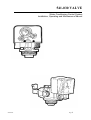
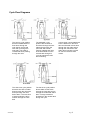
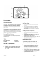
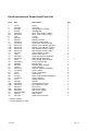
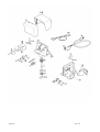
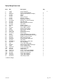
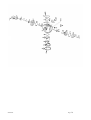
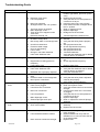
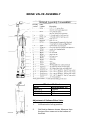
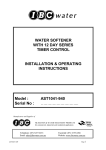
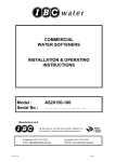
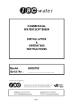
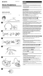
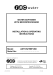
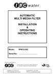
WATER SOFTENER
SERIES 500
12 DAY TIMER
INSTALLATION & OPERATING
INSTRUCTIONS
Model :
Serial No :
AS1029-E
………………………..
Manufacturer and Supplier of
FILTRATION & WATER TREATMENT PRODUCTS
for commercial, industrial and residential application
Telephone: (07) 3219 2233
Email: [email protected]
AS1029-E
Facsimile: (07) 3219 2266
Website: www.ibcwater.com.au
Page 1
HARDNESS TEST
1.
Water to be tested should be taken from a tap after the water softener
2.
Measure 10ml of water into plastic bottle supplied (approximately 1/3 full)
3.
Add one Yes/No tablet to sample water, replace cap and shake until tablet
has completely dissolved.
(NOTE: do not handle Yes/No tablet with fingers)
4.
The final colour to be obtained for soft water is green. (Note: The shade of
green may vary.) If the colour turns red, the water is above 20 mg/l hardness,
therefore another regeneration is recommended.
5.
Rinse plastic bottle after each test has been completed.
6.
When used as above, the tablets change the colour from green to red at a
hardness of approximately 20ppm based on a sample volume of 10mls.
Other hardness test kits are available for more accurate testing eg.
Hardness Tablets
Directions:
Take a 50ml sample of water in a screw capped bottle. Add one (1)
tablet to sample, shake or crush to disintegrate. Repeat until last trace
of reddish tinge disappears. The final colour is usually blue but with
some water a greyish coloured end point is obtained.
Using 50ml sample Hardness ppm = (number of tablets x 40) - 20
LR (BW) Tablets
Directions:
Take a 100ml sample of water in a screw capped bottle. Add one (1)
tablet to sample, shake or crush to disintegrate. Repeat until last trace
of reddish tinge disappears. The final colour is usually blue but with
some water a greyish coloured end point is obtained.
Using 100ml sample Hardness ppm = (number tablets x 2) – 1
Contact IBC Water if further details are required.
AS1029-E
Page 2
WATER SOFTENER CALCULATIONS
MODEL AS1029-E
To ascertain DAYS between regeneration periods the following data or estimations are
required.
(Let N be the number of days to be calculated)
.1.
ð
Water Hardness in mg/l
.2.
ð
Water Softener Hardness Removal Capacity
from Table 1 in grams
call ð
call
ð
.3.
call
ð
H
C
Daily Water Usage in litres
ð
D
For household situations allow 250 litres per person per day.
CALCULATION
N
=
1000 x C
DxH
Select nearest lower whole number
If necessary consult your dealer or IBC Water Treatment for advice on setting up the
softener.
EXAMPLE
Household use for 4 people on 220 mg/l hard water using
Model AS1029-E at 2030 grams capacity.
N
AS1029-E
=
1000 x 2030
1000 x 220
=
9.2 days
=
9 days
Page 3
LOCATION & INSTALLATION
1.
The softener should be located indoors or protected from the weather.
2.
The softener requires an inlet water pressure between 140kPa (20psi) and 690kPa
(100psi) and 240 volt 10 amp electric power supply.
2.
The softener should service all water lines in the house except the toilet and outside taps.
The softener should be positioned on a level flat surface close to a drain or any other
properly trapped waste outlet. The brass adaptors supplied are suitable for 20mm (3/4")
female fittings and the softener should be connected to the supply with raw water to the
inlet connector and softened water lines to the outlet as indicated on the valve. If
soldering fittings are used, the adaptors should be removed from the valve whilst the
fittings are being soldered.
3.
When facing the front of the control the inlet is to the right and the outlet is to the left.
4.
The system pressure must be between 140 kPa and 690 kPa psi.
5.
If the system pressure is greater than 690kPa psi a pressure reducing valve must be
installed.
6.
The unit must be installed in accordance with local codes.
7.
Do not over tighten connections.
8.
Drain line ID must be at least 12mm.
9.
Teflon tape should be used when installing he drain fitting into the control valve.
10.
The drain line must be free of kinks.
11.
A safety float with an air check is installed.
12.
Insure all connections are tight.
Note: DO NOT use teflon tape when connecting the fitting kits to the control valve.
13.
There are two drain lines, one from the brine tank and one from the softener valve, these
lines must have an air gap of at least 40mm or twice the pipe diameter at the drain
entrance. The drain line from the brine tank is gravity fed and hence the drain is required
to be below the outlet elbow on the tank.
14.
The drain line from the softener valve is under pressure during regeneration but for
correct operation a maximum of 2.4m of 15NB pipe with no rises can be connected.
A manual Bypass should be installed.
AS1029-E
Page 4
PLACING THE SOFTENER IN SERVICE
1.
Depress all Skipper Wheel Tabs.
2.
Turn knob (B) counter-clockwise until cam follower (G) has fully depressed drain valve
stem (H).
3.
Ensure the power is turned off at this stage. Open the installed inlet valve slightly and
slowly fill the mineral tank with water. Air and water will be expelled from drain line during
the filling process. When the mineral tank is full and the stream of water from the drain
line is steady, with no air bubbles, turn knob (B) counter-clockwise until cam follower (G)
springs back into position, allowing the drain valve stem (H) to return to the shut-off
position. Open the inlet valve fully. The salt storage tank will automatically fill to the
proper level. To check the level, remove the cabinet cover plate. If for any reason it does
not fill to this level, the bribe valve float must be raised or lowered as required. This level
will ensure the softener is set to produce maximum hardness removal.
4.
Again turn knob (B) counter-clockwise until cam follower (G) has fully depressed drain
valve stem (H). Water will run from drain line and water in the salt storage tank will be
lowered approximately to the centre of the brine valve air shut-off assembly. Let water run
about 5 minutes longer or until water is clear and then turn timer knob (B) counterclockwise until cam follower (G) springs back into position, again allowing the drain valve
stem (H) to return to the shut-off position. Open installed outlet valve and be sure that the
installed by-pass valve is closed.
BRINE TANK
1.
Place at least 25kg of a coarse refined grade of salt (Water Softener Salt) in the brine
tank and always maintain dry salt above the water level.
The tank can hold up to 50kg of coarse salt.
2.
Periodically it will be necessary to allow the salt to "run-out" and clean out the brine tank
of accumulated silt and insoluble material.
REGENERATION
This automatic water softener is designed for a minimum complete regeneration time of 70
minutes. Under normal conditions the regeneration cycle should be set to 70 minutes. However,
if the pressure is low, the time may have to be increased to 90 minutes.
AS1029-E
Page 5
REGENERATION FREQUENCY
The softener can be set to regenerate from once per day up to once per 12 days. To
determine the correct number of regenerations refer to the Tables below for the model
softener installed. The skipper wheel tabs are pushed in fully for the days selected for
regeneration. The factory setting for the actual time of regeneration is 3am.
The tables below are based on an average daily water usage of 250 litres per person and
using the maximum salt dosage to provide maximum capacity. The tables indicate a
suggested number of regenerations per 12 day period.
The tabs selected will have to suit the suggested number eg. For 6 regenerations, select
tabs, 1, 3, 5, 7, 9, 11. From the left column locate the number in the family, reading along
and down from the hardness column, where the column intersect gives the number of
regenerations for every 12 days.
MODEL AS0715-E
No. in
family
1
2
3
4
5
6
Hardness MG/L CACO3
50
1
1
1
1
1
1
100
1
1
1
2
2
2
150
1
1
2
2
3
3
200
1
2
2
3
3
4
250
1
2
3
3
4
6
300
1
2
3
4
6
6
350
2
3
4
6
6
400
2
3
4
6
6
450
2
3
4
6
500
2
3
6
6
400
1
2
3
4
4
6
450
1
2
3
4
6
6
500
1
2
3
4
6
6
400
1
2
2
3
4
4
450
1
2
3
3
4
6
500
1
2
3
4
4
6
MODEL AS0922-E
No. in
family
1
2
3
4
5
6
Hardness MG/L CACO3
50
1
1
1
1
1
1
100
1
1
1
1
1
2
150
1
1
1
2
2
2
200
1
2
2
2
2
3
250
1
1
2
2
3
3
300
1
2
2
3
3
4
350
1
2
3
3
4
6
MODEL AS1029-E
No. in
family
1
2
3
4
5
6
AS1029-E
Hardness MG/L CACO3
50
1
1
1
1
1
1
100
1
1
1
1
1
1
150
1
1
1
1
2
2
200
1
1
1
2
2
2
250
1
1
2
2
2
3
300
1
1
2
2
3
3
350
1
2
2
3
3
4
Page 6
AS1029-E
Page 7
541-030 VALVE
Water Conditioning Control System
Installation, Operating and Maintenance Manual
AS1029-E
Page 8
Cycle Flow Diagrams
The service cycle position
directs untreated water to
flow down through the
resin bed in the mineral
tank and up through the
riser tube. The water is
conditioned when passing
through the resin.
The backwash cycle
position directs water to
flow down through the riser
tube and up through the
resin bed and to drain.
Foreign material and resin
fines are flushed from the
mineral tank during this
cycle to prepare the resin
bed for brining.
The slow rinse cycle position
directs a slow flow of water
down through the riser tube
and up through the resin
bed to drain. This slow flow
of water pushes the brine
solution through the resin
bed.
The fast rinse cycle position
directs water to flow down
through the riser tube and up
through the media bed and to
drain. Foreign material is
flushed from the mineral tank
during this cycle.
AS1029-E
In brine draw, concentrated salt
brine is drawn from the brine
tank and directed to flow down
through the riser tube and up
through the resin bed to the
drain. Brine is drawn until the
air check in the brine tank
closes.
Page 9
Programming
General Information
Set Time of Day
The control valve is designed to initiate regeneration
according to pre-set factory parameters. Following
the instructions contained in this section will allow
the installer to customise the program for the users
exact needs.
The regeneration cycle is controlled by the time cam
located on the front of the timer assembly. The brine
& slow rinse cycle can be adjusted from 50 minutes
to 95 minutes in 5 minute increments. The backwash
and fast rinse cycles are not adjustable.
Factory Default Settings
The following default cycle settings are preset into
the control valve.
Cycles:
Backwash
Brine / Slow Rinse
Fast Rinse
11 1/2 minutes
70 minutes
4 1/2 minutes
Set Time of Regeneration
1. Remove the front dust cover from the timer
assembly.
2. Rotate the Time of Regeneration plate (A) until
the desired time appears in the window. Note
A.M. or P.M.
AS1029-E
1. Remove the front dust cover from the timer
assembly.
2. Turn the Timer Knob (B) until the alignment
mark located on the Time of Day Gear (C)
points directly to the correct time of day. Note
A.M. or P.M.
Set Regeneration Frequency
1. Remove the front dust cover from the timer
assembly.
2. Pull all skipper wheel tabs up.
3. Rotate skipper wheel (D) until the number one
tab aligns with the DAY mark (E)
4. Starting with the number one tab, push down the
tabs to determine the days on which
regeneration is required.
Regeneration Cycles
The backwash and fast rinse cycles are nonadjustable. Adjusting the brine and slow rinse cycle
can be accessed according to the following
procedure:
1. Loosen the screw located on top of the timer
cover, remove front dust cover from timer
assembly.
2. Turn Timer Knob (B) until setscrew on the time
cam is visible.
3. Loosen setscrew, and using the alignment mark
(F) located on the lower cam, move timing cam
to the desired length of time.
4. Tighten setscrew and install dust cover.
Page 10
Electromechanical Power Head Parts List
Item
P/N
Description
Qty
1.
2.
3.
4.
5A.
5B.
6.
7.
8.
9.
10.
11A.
11B.
12A.
12B.
13.
14.
15.
16.
17.
18.
19
20.
21.
22.
23.
24.
25.
26.
27.
28.
29.
30A.
30B.
31.
32A.
32B.
33.
34.
35.
15-76
529-309
525-303
52-308
529-232-1
529-232-2
19-3
529-218
529-212
529-333-1
15-185-10
525-274-1
525-274-2
525-241-2
525-241-4
525-205
15-87
529-239-1
529-219-3
401-7
185-0221-1
529-286
529-280
15-92-2
525-279-4
15-185-10
15-76
30-77 *
516-221
15-185-10
14-11
525-260
525-254-2
525-254-5
529-234 **
529-220-1
529-220-2
529-290-14BK
28-8-28
28-142-2
Screw
Time Dial
Spring Washer, (Small)
Locating Dial
Gear, Time of Day (12 Day)
Gear, Time of Day (7 Day)
C -clip
Actuator
Spindle, Actuator
Housing, Power Head
Screw, Day Selector Wheel
Washer, Day Indicator (12 Day)
Washer, Day Indicator (7 Day)
Day Selector Wheel (12 Day)
Day Selector Wheel (7 Day)
Spring Washer, (Large)
Screw, Head Mount
Cycle Cam & Knob Assembly
Drain Plunger Assembly
return Spring, Drain Plunger
O-ring, Plunger Cap
Plunger Cap
Retainer, Drain Plunger
Screw, Retainer
Switch & Terminal Assembly
Screw, Switch
Screw, Timer Motor
Timer Motor
Return Spring, Main Diaphragm
Screw, Ratchet
Washer, Ratchet
Ratchet
Gear Ratchet (12 Day)
Gear Ratchet (7 Day)
Front Cover
Rear Cover (Gray)
Rear Cover (White)
Solenoid Cord
Strain Relief
Power Cord (120 Volt)
1
1
1
1
1
1
1
1
1
1
1
1
1
1
1
1
4
1
1
1
1
1
1
1
1
2
2
1
1
1
1
1
1
1
1
1
1
1
1
1
* Indicate Voltage
** Indicate Opaque or Clear
AS1029-E
Page 11
AS1029-E
Page 12
Valve Body Parts List
Item
P/N
Description
Qty
1.
2.
3.
4.
5.
6.
7.
8.
9.
10.
11.
12.
13.
14.
15.
16.
17.
18.
19.
20.
21.
22.
23.
24.
25.
26.
27.
28.
29.
30.
31.
32A.
32B.
33.
34A.
34B.
35A.
35B.
36.
37.
15-88
15-90
413-134 *
413-60
413-58
413-62
413-61
413-59
541-208-2
541-206
541-239
541-246
541-325
428541-221
15-89
413-13
541-254
186-111-N
541-250-1
19-19
541-243
529-244
541-244
185-024-1
541-204
185-028-12
541-256
19-3
516-221
19-90
185-231-1
186-105
541-232
185-211-1
185-214-1
541-205
541-218
185-029-1
541-257-1
Screw, Backcap
Screw, Solenoid Mount
Solenoid Coil (Specify Voltage)
Spacer
Guide
Spring, Plunger
Plunger, Solenoid
Diaphragm, Solenoid
Backcap, 5 Cycle Fast Rinse
Seal, Backcap
Return Spring, Check Disc
Check Disc
Gasket, Injector
Injector (Specify Size)
Cover Plate, Injector
Screw, Injector Mount
Filter Screen, Injector
Spring Clip
O-ring, Brine Fitting
Brine Fitting
C-Clip, Backwash Flow Adjuster
Backwash Flow Adjuster w/o-rings
Gasket, Cross Over Port
Body Stem Assembly
O-ring (Small), Seat Insert
Seat Insert
O-ring (Large), Seat Insert
Main Diaphragm
C-clip, Main Diaphragm
Return Spring, Main Diaphragm
Screw, Adapter Ring
O-ring, Structural Tank
O-ring, Park Tank
Adapter Ring
O-ring, 13/16" Riser Adapter
O-ring, 1.050" Riser Adapter
Power Cord (120 Volt)
13/16" Riser Adapter
1.050" Riser Adapter
Valve Body & Seal
3
1
1
1
1
1
1
1
1
1
1
1
1
1
3
1
1
1
1
1
1
1
1
1
1
1
1
1
1
2
1
1
1
1
1
1
1
1
1
4
* Indicate Voltage
AS1029-E
Page 13
AS1029-E
Page 14
Troubleshooting Guide
Problem
1. Unit fails to regenerate.
Cause
a. Faulty electrical circuit.
b. Defective clock motor.
c. Low inlet pressure.
d. Drain line restricted.
e. All skipper tabs in the "out" position.
2. Hard water to service.
f. The brine injector is plugged.
g. Main diaphragm is torn.
h. Timer knob out of alignment with
Time Gear.
i. Defective solenoid coil.
a. The bypass valve is open or faulty.
b. No salt in storage tank.
c. Not enough water in the storage tank.
d.
e.
f.
g.
h.
i.
3. Excessive salt usage.
4. Loss of resin.
5. Salt water to service.
6. Control fails to draw
brine.
Unit fails to draw brine.
Excessive water usage.
Unit not regenerating.
Loss of resin.
Change in raw water hardness.
Leak at the distributor tube.
i.
a.
b.
c.
d.
e.
f.
g.
h.
i.
a. Excessive water in storage tank.
a.
b. Regeneration is taking place too
frequently.
c. Faulty safety float.
a. Faulty air check in storage tank.
b. Leak at the distributor tube.
b.
c. Backwash flow improperly adjusted.
a. Brine/slow rinse cycle time set too
short.
b. Excessive water in the storage tank.
c. Brine injector undersized.
a. Brine injector plugged.
b. Filter screen plugged
c. Loose brine line connection.
d. Drain line is restricted
e. Low inlet pressure.
f. Main diaphragm is torn.
g. Solenoid plunger stuck open.
7. Continuous flow to
drain.
a. Drain plunger stuck open.
b. Clock motor stalled.
8. Loss of water pressure.
a. Iron build up in mineral tank.
b. Lower distributor basket crushed.
c.
AS1029-E
Solution
a. Verify electrical service (fuse, circuit
breaker, light switch, pull chain, power
cord).
b. Replace the clock motor.
c. Verify that the service inlet pressure is
a minimum of 20 psi.
d. Insure the drain line is free of kinks.
e. Push desired number of skipper tabs to
the "in" position.
f. Clean or replace injector.
g. Replace diaphragm.
h. Realign the Knob and Gear.
Resin has lost mechanical strength.
Test and replace the solenoid coil.
Close bypass valve.
Add salt.
Verify that the safety float is properly
set.
See symptom/cause # 6.
Check regeneration frequency.
See symptom/cause # 1.
See symptom/cause # 4.
Test water hardness.
Verify that the distributor tube is seated
correctly and is not cracked.
Verify that the safety float is properly
set.
Check regeneration frequency.
c. Replace safety float.
a. Clean or replace air check.
b. Verify that the distributor tube is seated
correctly and is not cracked.
c. Verify the backwash flow.
a. Verify cycle time.
b. Verify that the safety float is adjusted
correctly and properly.
c. Verify proper injector selection.
a. Clean and replace injector.
b. Clean and replace screen.
c. Verify that all the brine line connections
are tight.
d. Insure that the drain line is not kinked
or plugged.
e. Verify that the service inlet pressure is
a minimum of 20 psi.
f. Replace diaphragm.
g. Clean or replace the solenoid plunger
assembly.
a. Clean or replace the drain plunger
assembly.
b. Replace the clock motor.
a. Increase salt dosage or regenerate
more frequently.
b. Replace basket and verify that the
distributor is cut 1/2 inch below the top
of the tank threads.
c. Replace resin
Page 15
Parts Replacement
General Information
Main Diaphragm Replacement
Familiarise yourself with the parts replacement
procedures and component parts thoroughly before
attempting any repair.
Insure that the unit is in the bypass position and
relieve the system pressure before attempting any
repair procedure.
WARNING! Disconnect all electrical power to the
unit before attempting and repair procedure.
Required Tools
The following tools are required to perform routine
maintenance on this valve:
Phillips Screwdriver
Needle Nose Pliers
Adjustable Wrench
Small Standard Screwdriver
Timer Assembly Replacement
1. Disconnect all electrical power to the control.
2. Place the bypass valve into "bypass" position.
3. Remove the front dust cover from the timer
assembly.
4. Relieve the system pressure by using a
screwdriver to press down on the drain plunger
opening the drain line.
5. Disconnect the solenoid cable from the solenoid
coil.
6. Remove the four (4) head mounting screws.
7. Lift the timer assembly away from the valve
body.
8. Follow these steps in reverse to reinstall the
timer assembly.
Note: Prior to re-instalment insure that the
main return spring is centred over the main
diaphragm.
Timer Motor Replacement
1. Disconnect all electrical power to the control.
2. Remove both the front dust cover and the rear
timer cover.
3. Disconnect the two (2) wire nuts from the timer
motor leads.
4. Remove the two (2) motor mount screws.
5. Lift the motor away from the timer assembly.
6. Follow these steps in reverse to reinstall the
timer assembly.
AS1029-E
1. Disconnect all electrical power to the control.
2. Place the bypass valve into the "bypass"
position.
3. Remove the front dust cover from the timer
assembly.
4. Relieve the system pressure by using a screwdriver to press down on the drain plunger
opening the drain line.
5. Disconnect the solenoid cable from the solenoid
coil.
6. Remove the four (4) head mounting screws.
7. Lift the timer assembly away from the valve
body.
8. Remove the c-clip from the centre of the
diaphragm.
9. Lift the diaphragm away from the body stem
assembly.
7. Follow these steps in reverse to reinstall the
timer assembly.
Note: Prior to re-instalment insure that the
main return spring is centred over the main
diaphragm and that the outside edges of the
main diaphragm are tucked into the valve
body.
Drain Plunger Replacement
1. Disconnect all electrical power to the control.
2. Place the bypass valve into "bypass" position.
3. Remove the front dust cover from the timer
assembly.
4. Relieve the system pressure by using a
screwdriver to press down on the drain plunger
opening the drain line.
5. Remove the retaining screw located below the
"Time of Day" gear.
6. Lift the retainer down and away from the timer
assembly.
7. Press down on the drain plunger to remove it
from the valve body.
8. Inspect the plunger o-rings and centre cup for
wear.
9. Clean out the plunger orifice in valve body.
10. Use a Dow 111 Silicone based lubricant to
lightly lubricate the plunger o-rings and the valve
body orifice.
11. Follow these steps in reverse to re-install drain
plunger.
Page 16
Injector and Filter Screen
Replacement
1. Disconnect all electrical power to the
control.
2. Place the bypass valve into the "bypass"
position.
3. Remove the front dust cover from the timer
assembly.
4. Relieve the system pressure by using a
screwdriver to press down on the drain
plunger opening the drain.
5. Remove the three (3) screws from the
triangular cover plate.
6. Lift away the cover plate.
7. Remove the injector from valve body and
separate the gasket from the injector.
8. Inspect the injector cavities for blockage.
9. Remove the filter screen from the valve
body and inspect the screen for dirt.
Replace if necessary.
10. Follow these steps in reverse to re-install the
riser assembly.
Note: After backing out the drain seat the
seat may still require minor adjustment
to eliminate leaks. Turn the seat in or out
until the leak to drain stops.
Riser Replacement
1. Disconnect all the electrical power to the control.
2. Place the bypass valve into the "bypass"
position.
3. Relieve the system pressure.
4. Disconnect the unit from the bypass
connections.
5. Remove the unit from the resin tank.
6. Turn out the upper distributor basket from the
unit adapter ring.
7. Remove the two (2) adapter hold down screws,
and lift away the adapter ring.
8. Separate riser assembly from valve body.
9. Clean the riser o-rings and wipe out the valve
body cavity.
10. Use the Dow 111 Silicone based lubricant to
lightly lubricate the riser o-rings and the valve
body cavity.
11. Follow these steps in reverse to re-install the
riser assembly.
AS1029-E
Check Disc Replacement
1. Disconnect all electrical power to the control.
2. Place the bypass valve into the "bypass"
position.
3. Relieve system pressure.
4. Disconnect the solenoid cable from the solenoid
coil.
5. Remove the four (4) screws from the backcap.
6. Place a hand under the backcap and remove the
backcap. The check disc return spring will fall
into your hand.
7. Remove the check disc from the back of the
body stem assembly.
8. Inspect the rubber seal on the check disc for
wear. Clean or replace if necessary.
9. Re-install the check disc on body stem
assembly.
10. Place a small amount of Dow 111 silicone based
lubricant on the back cap centre post.
11. Insure that the back cap gasket is properly
seated in Backcap.
12. Install check disc return spring into centre post.
13. Align the mark on top of the back cap with the
mark on the valve body and carefully direct
open end of return spring into centre post of the
check disc.
14. Install the four (4) back cap screws.
15. Pressurise system and check for leaks.
Body Stem Assembly Replacement
1. Disconnect all electrical power to the control.
2. Place the bypass valve into the "bypass"
position.
3. Remove the front dust cover from the timer
assembly.
4. Relieve the system pressure by using a screwdriver to press down on the drain plunger to the
open drain line.
5. Disconnect the solenoid cable from the solenoid
coil.
6. Remove the four (4) head mounting screws.
7. Lift the timer assembly away from the valve
body.
8. Remove the c-clip from the centre of the
diaphragm.
9. Lift the diaphragm away from the body stem
assembly.
10. Remove the seat assembly.
11. Lift out the body stem assembly.
12. Inspect the centre check disc rubber seal for
wear. Clean or replace if necessary.
13. Re-install the body stem assembly.
14. Lightly lubricate the seat assembly o-rings with a
Dow 111 Silicone based lubricant.
Page 17
12. Follow these steps in reverse to re-install the
backwash adjustment valve.
15. Re-install the seat assembly, insure that one of
the two (2) flats is facing towards the top of the
valve body.
16. Re-install the main diaphragm and the timer
assembly.
17. It is now necessary to reseat the rear check disc.
Refer to the Check Disc Replacement
procedure.
Backwash Adjustment Valve
Replacement
1. Place the bypass valve into the "bypass"
position.
2. Relieve the system pressure. Remove the four
(4) head mounting screws.
3. Lift the timer assembly away from the valve
body.
4. Remove the c-clip from the centre of the
diaphragm.
5. Lift the diaphragm away from the body stem
assembly.
6. Remove the seat assembly.
7. Disconnect the large c-clip located on top of the
backwash adjustment valve.
8. Press the backwash adjustment valve down and
out through the valve body assembly.
9. Inspect the o-rings on the valve for wear. Clean
or replace the valve assembly if necessary.
10. Lightly lubricate the o-rings with a Dow 111
Silicone based lubricant.
11. Follow these steps in reverse to re-install the
backwash adjustment valve.
Solenoid Assembly Replacement
1. Disconnect all electrical power to the control.
2. Place the bypass valve into the "bypass"
position.
3. Relieve the system pressure.
4. Disconnect the solenoid cable from the solenoid
coil.
5. Remove the one (1) solenoid mounting screw.
6. Lift away the solenoid coil. Test coil and replace
if necessary.
7. Remove the three (3) remaining screws, which
hold down the solenoid plunger retainer.
8. Place a hand under the plunger retainer while
lifting away the retainer assembly.
9. Verify that the plunger moves back and forth
against the return spring without sticking. Clean
or replace if necessary.
10. Separate the solenoid diaphragm from the valve
body. Verify that the diaphragm cavity in the
valve body is free of debris.
11. Inspect the diaphragm for rips or tears. The
diaphragm should have a hole in the centre and
a smaller "pin" hole off centre
AS1029-E
Page 18
BRINE VALVE ASSEMBLY
Windsor Cabinet
Model
AS0715-E
AS0922-E
AS1029-E
Float Distance (X)
100mm
200mm
260mm
Adjustment of Softener Brine Valve
AS1029-E
1.
Lift float rod to full up position.
2.
Set float to distance shown. Measure from
the top of the crown nut to the bottom of
Page 19
the float.