1
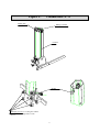
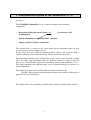
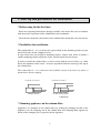
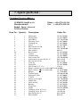
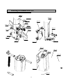
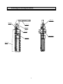
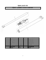
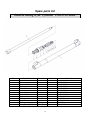
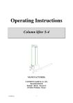
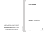
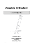
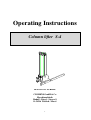
Operating Instructions Column lifter S-4 MANUFACTURER: CLEMENS GmbH & Co Maschinenfabrik Rudolf - Diesel - Strasse 8 D-54516 Wittlich / Mosel 1 Contents : Page: 1. Foreword 3 2. Functional description of the column lifter S-4 5 3. Start-up and possibilities for installation 6 - Before using for the first time - Possibilities for installation - Mounting appliances on the column lifter S-4 - Hydraulic circuit diagram "Column lifter S4" 6 6 6 6 4. Maintenance and care 7 5. Safety 8 6. Technical data 9 - Declaration of conformity 10 Spare parts list 11-15 7. Note : The manufacturer cannot accept any liability for damage and losses due to noncompliance with the Operating Instructions or to the use of impermissible spare parts. The column lifter must not be modified, extended or converted in any way capable of impairing its safety without the manufacturer's prior consent. Subject to change without notice! 1999 CLEMENS GmbH & Co All rights reserved ! 2 1. Foreword : Dear user ! The CLEMENS column lifter S-4 is a product from the range of All-around weeders from CLEMENS which will make it very much easier for you to maintain your vineyard all around the vine. So that the column lifter can be used safely and correctly for its intended purpose, it is essential to read these Operating Instructions before using the product and scrupulously to follow all the instructions. Ensure that you are familiar with the principle of operation of the column lifter and other fitted attachments before starting work. General note : - The column lifter may only be operated when all guards and safety mechanisms are in place and functioning correctly. - All faults and malfunctions capable of impairing safety must be remedied immediately by specialist personnel. - The column lifter may only be used to lift out tillage implements mid-mounted on the tractor. - The hydraulic connections of the column lifter must not be modified, as this will lead to malfunctions and endanger both yourself and other people. - Repairs should only be carried out by specialist repairshops or the CLEMENS Customer Service Centre. Never undertake any unauthorized modifications on the device. - The instructions supplied with the attachments must also be read with care. 3 Figure 1 : Column lifter S - 4 Sliding tube Plunger cylinder Column Sliding block Clamping screws for securing the column lifter to the mounting bracket on the tractor 4 2. Functional description of the column lifter S - 4: (See Fig. 1) The CLEMENS column lifter S - 4 essentially comprises the following components: - Hexagonal sliding tube inside a hexagonal Column column as enclosure, with clamping plate - Spindle adjustment as depth limitation (optional) - Plunger cylinder with hose connections The column lifter is secured to the square block on the mounting bracket of your tractor by means of four clamping screws. If your tractor does not include a mounting bracket, contact your dealer to obtain a suitable mounting bracket which the dealer can then install on your tractor. The underlying principle of the column lifter is that a single-acting hydraulic cylinder raises or lowers your attachment when the hydraulic control is actuated from the driver's seat. The hydraulic cylinder has a maximum stroke length of 500 mm (19.7“). The depth limitation and working height can be adjusted manually by means of a spindle adjustment. The mounting bracket can be installed both vertically and horizontally. The three sliding blocks on the hexagonal column ensure that the sliding tube is guided linearly and without play. The column lifter is also optionally available with a double-acting hydraulic cylinder. 5 3. Start-up and possibilities for installation: * Before using for the first time: - Read the Operating Instructions through carefully and ensure that you are familiar with the mode of operation of the column lifter and attachments. - Check that the hydraulic connections of the column lifter match those on your tractor. * Possibilities for installation: The column lifter S – 4 is secured to the square block on the mounting bracket of your tractor by means of four clamping screws. If your tractor does not include a mounting bracket, contact your dealer to obtain a suitable mounting bracket which the dealer can then install on your tractor. In order to install the column lifter, it can be raised with the aid of a hoist (e.g. chain hoist) and mounted on the tractor. It can be suspended from the crane lug at the top of the column lifter. The column lifter S – 4 is connected to the hydraulic system of the tractor by means of quick-release detent couplings. Connection to tractor Connection to tractor Plunger cylinder Double-acting cylinder (OPTIONAL) * Mounting appliances on the column lifter: Appliances are mounted on the column lifter by sliding the clamping bracket of the appliance over the clamping rail of the column lifter and clamping them together by means of the clamping device provided on the appliance. 6 4. Maintenance and care: The column lifter is designed to require minimum maintenance and care. The following points must be noted, however: - All screws and bolts must be checked after the first five hours of operation in order to ensure that they are secure. - When cleaning the column lifter with a high-pressure cleaner and fitted attachments, care must be taken to ensure that the high-pressure jet is not directed towards bearings and seals or hydraulic connections, as this could lead to damage and premature failure of the lifter. - After cleaning, the guideways should be lightly greased with sulphur-free grease. This increases the service life of your column lifter. - The hydraulic fluid should be filtered at some point in the hydraulic system of the tractor. - The grease nipples on the sliding tube must be lubricated every 20 hours of operation. - If play develops between the sliding tube and column, the three sliding blocks must be adjusted until the sliding tube moves without play. * Possible reasons for a major rise in oil temperature: - Nominal size of the intake, delivery and return hose lines is too small. - The oil tank (reservoir) is too small. - The oil level in the tractor's hydraulic system is too low. - The oil filter is fouled. - The required oil quantity is not achieved. - The setting of the pressure limiting valve on the tractor is too low. 7 5. Safety: - Before starting to use the appliances, read through the associated operating instructions and follow their safety instructions without fail. - No-one is permitted within a radius of at least 10 metres (11 yards) of the appliances mounted on the column lifter during operation, since all rotating or slewing tools constitute a hazard. - Before use, the hydraulic lines must be examined for signs of damage and ageing and must be replaced if necessary. Note the expiry dates printed on the hoses and possibly also on the screw couplings. Important: Splashing oil can cause injuries and endanger the environment! - Goggles must be worn without fail if there is any risk of earth, stones or other objects being hurled aside during operation of the attachments. - Maintenance and repair work may only be undertaken when the hydraulic lines have been disconnected from the tractor. (Risk of crushing! ) - The column lifter and appliances must never be used by anyone who has not read the safety and operating instructions. - The accident prevention regulations of the employers' liability insurance association must be observed. - Due to the noise generated when operating the appliances, hearing protection must be worn without fail when working on a tractor with open driver's cab. - The column lifter and appliances may only be used during sufficient daylight in order to avoid the risk of accidents. 8 6. Technical data: Weight (without appliances) : approx. 55 kg (121 lb) Dimensions without appliances : LxWxH: Stroke of the column lifter (maximum) : 500 mm (19.7“) 9 235 x 700 x 970 mm (59.7 x 57.6 x 38.2 “) EC Declaration of Conformity in accordance with EC Directive 89/392/EEC "Machines", Annex II A CLEMENS & Co GmbH Maschinenfabrik Rudolf - Diesel - Strasse 8 D-54516 Wittlich / Mosel Manufacturer : We herewith declare that the mechanical design of the Machine type : Column lifter S 4 complies with the following relevant regulations (Directives): Directive on machines 89/392/EEC Official Journal of the EC, No. L 183/9 91/368/EEC 93/44/EEC 93/68/EEC Amended by Directive The following harmonized standards have been applied: DIN EN 292 , Part 1 DIN EN 292 , Part 2 The following national technical standards and specifications have been applied: DIN v 8418 Particulars of the authorized signatory Surname, first name: Clemens, Bernd Position : Managing Director Wittlich, 08.09.2000 Place, date ____________________________ Legal signature 10 7. Spare parts list : Customer Service address : CLEMENS GmbH & Co Maschinenfabrik Rudolf - Diesel - Strasse 8 D-54516 Wittlich Item No.: Qantity: 1 2 3 4 5 6 7 8 9 10 11 12 13 14 15 16 17 18 19 19 20 21 22 23 24 25 26 27 28 29 30 31 32 33 1 2 3 3 1 2 2 4 4 1 1 1 4 2 4 1 1 1 1 1 2 1 1 1 2 1 1 1 1 1 1 1 1 1 Phone: ++49-6571-929-220 Fax: ++49-6571-929-192 Description: Order No.: Sliding tube CL 866.703000 Sliding block CL 866.700003 Quard Ring CW 780.025100 Adjusting screw CL 866.700002 Clamping bar CL 866.700009 Spacer CL 866.700008 Hex bolt M 16 x 100 0931 16 100 Lock washer ø 12 CW 520.002900 Hex nut M 12 0934 12 Basic bracket CL 866.701000 Column CL 866.702000 Graduated ring CL 866.700005 Lock washer ø16 CW 520.003100 Socket head cap screw M 16 x 35 0912 16 035 Hex bolt M 12 x 50 0931 12 050 Crane lug CL 866.700006 Spring bolt CL 866.704000 Lock washer ↵ 15 x 1,5 6799 15 Plunger cylinder sa ø 25, stroke=500CL 895.660000 Hydr. cylinder da ø 22, stroke=460 CL 895.670000 Rollpin CL 729.010003 Tension spring CW 009.021200 Spring bolt, short CL 866.700001 V-block CL 866.700004 Impact grease nipple CW 570.000100 Spindle unit CL 866.709100 Guide bearing CL 866.709200 Bushing CL 866.709203 Toggle hub CL 903.010002 Toggle CW 031.000100 Clamping sleeve Ø 3 x 24 1481 03 024 Clamping sleeve Ø 6 x 25 1481 06 025 Hex bolt M 10 x 55 0931 10 055 Hex nut M10 0985 10 11 Drawing of column lifter S-4 Item. 1 Item 11 Item. 2 Item 10 Item 3. 3 Item. 24 Item. 4 Item. 12 Item. 9 Item 5 Item. 8 Item. 13 Item. 6 Item. 7 Item. 14 Item 15 Item 16 Item 17 Item 19 Item 18 Item 20 Item Item 21 Item 22 12 Drawing of the depth limiter Item 24 Item 27 Item 29 Item 31 Item 30 Item 32/33 Item 25 Item 26 13 Spare parts list Hydr. cylinder CL895.660000 Item Specification 1 Cylinder pipe 2 Piston 3 Bushing 5 Dust shield 6 Piston seal 7 O-Ring 8 Hexagon screw 9 Lock washer 10 Washer Dimension Quant Order-N° 1 CL895.661000 1 CL895.662000 1 CL895.660001 1 CW780.003200 1 CW780.003100 1 OR04225 1 093310020 1 CW520.002800 1 902110 ∅42x2,5 M10x20 ∅10 ∅10,5 14 Spare parts list Double acting hydr. cylinder CL895.670000 Item Specification 1 Cylinder pipe 2 Piston 3 Bushing 4 Guide 5 Junk ring 6 Junk ring 7 Dust shield 8 Piston seal 9 O-Ring 10 Seal kit 11 O-Ring 12 Hexagon nut (1/2) Dimension Quant Order-N° 1 CL895.671000 1 CL895.672000 1 CL895.400001 1 CL895.400004 1 CL895.400003 1 CL895.022003 1 CW780.003600 1 CW780.003000 1 OR03225 2 CW780.002900 1 OR01520 1 093612015 ∅32x2,5 ∅15x2 M12x1,5 15