1
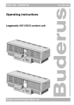
Operating Instructions
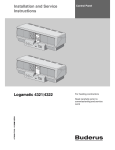
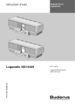
Logamatic 4323
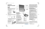
Control panel
For the user
6 720 618 563 - 11/2008 US/CA
Please read carefully before
use
Contents
1
Introduction .
2
What you should know about your heating system .
3
Tips on energy-efficient heating
4
Safety .
4.1
4.2
4.3
4.4
4.5
4.6
4.7
5
7
About this manual . . . . . . . . . . . . .
Intended use . . . . . . . . . . . . . . . .
Standards, regulations and directives .
Key to symbols . . . . . . . . . . . . . . .
Please observe these notes. . . . . . .
Cleaning the control panel . . . . . . . .
Disposal . . . . . . . . . . . . . . . . . . .
Controls on the control panel .
MEC2 remote control . . . . . .
Switching on the control panel
Switching off the control panel
. . . . . . . . . . . . . . . . . . . . . . . . . . . . . 11
. . . . . . . . . . . . . . . . . . . . . . . . . . . . . 11
. . . . . . . . . . . . . . . . . . . . . . . . . . . . . 11
. . . . . . . . . . . . . . . . . . . . . . . . . . . . . 11
. . . . . . . . . . . . . . . . . . . . . . . . . . . . . 11
. . . . . . . . . . . . . . . . . . . . . . . . . . . . . 12
. . . . . . . . . . . . . . . . . . . . . . . . . . . . . 12
. . . . . . . . . . . . . . . . . . . . . . . . . . . . 13
. . . . . . . . . . . . . . . . . . . . . . . . . . . . . . . . . . 13
. . . . . . . . . . . . . . . . . . . . . . . . . . . . . . . . . . 14
. . . . . . . . . . . . . . . . . . . . . . . . . . . . . . . . . . 16
. . . . . . . . . . . . . . . . . . . . . . . . . . . . . . . . . . 16
. . . . . . . . . . . . . . . . . . . . . . . . . . . . . . . . . . . . . . . . . . . . 17
Simple operation. . . . . . .
Permanent display . . . . .
Select operating mode . . .
Set the room temperature .
DHW heating . . . . . . . . .
Extended functions
7.1
7.2
7.3
7.4
7.5
7.6
7.7
7.8
7.9
7.10
7.11
7.12
7.13
7.14
7.15
7.16
2
. . . . . . . . . . . . . . . . . . . . . . . . . . . . . . . . . . . . . . . . . . . . . . . . . . . 11
Basic functions
6.1
6.2
6.3
6.4
6.5
. . . . . . . . . . . . . . . . . 5
. . . . . . . . . . . . . . . . . . . . . . . . . . . . . . . 10
Controls and MEC2 remote control .
5.1
5.2
5.3
5.4
6
. . . . . . . . . . . . . . . . . . . . . . . . . . . . . . . . . . . . . . . . . . . . . . . 4
. . . . . . . . . . . . . . . . . . . . . . . . . . . . . . . . . . . . 17
. . . . . . . . . . . . . . . . . . . . . . . . . . . . . . . . . . . . 18
. . . . . . . . . . . . . . . . . . . . . . . . . . . . . . . . . . . . 19
. . . . . . . . . . . . . . . . . . . . . . . . . . . . . . . . . . . . 22
. . . . . . . . . . . . . . . . . . . . . . . . . . . . . . . . . . . . 24
. . . . . . . . . . . . . . . . . . . . . . . . . . . . . . . . . . . . . . . . . 27
Buttons for extended functions . . . . . . . . . . . . . . . .
Controlling the extended functions . . . . . . . . . . . . . . .
Displaying operating values . . . . . . . . . . . . . . . . . . .
Changing the permanent display . . . . . . . . . . . . . . . .
Setting the date and time . . . . . . . . . . . . . . . . . . . .
Selecting a heating zone. . . . . . . . . . . . . . . . . . . . .
Adjusting the room temperature for another heating zone
Heating zones with MEC2 remote control . . . . . . . . . .
Selecting and modifying a heating program . . . . . . . . .
Selecting a standard program . . . . . . . . . . . . . . . . .
Summary of standard programs . . . . . . . . . . . . . . . .
Modifying the standard program by moving set points . .
Set warm weather shut down (WWSD) temperature. . . .
Setting the DHW operating mode . . . . . . . . . . . . . . .
Setting the operating mode for DHW recirculation . . . . .
Set the vacation function. . . . . . . . . . . . . . . . . . . . .
. . . . . . . . . . . . . . . . . 27
. . . . . . . . . . . . . . . . . 28
. . . . . . . . . . . . . . . . . 28
. . . . . . . . . . . . . . . . . 29
. . . . . . . . . . . . . . . . . 30
. . . . . . . . . . . . . . . . . 31
. . . . . . . . . . . . . . . . . 32
. . . . . . . . . . . . . . . . . 34
. . . . . . . . . . . . . . . . . 35
. . . . . . . . . . . . . . . . . 37
. . . . . . . . . . . . . . . . . 38
. . . . . . . . . . . . . . . . . 39
. . . . . . . . . . . . . . . . . 41
. . . . . . . . . . . . . . . . . 43
. . . . . . . . . . . . . . . . . 44
. . . . . . . . . . . . . . . . . 45
Logamatic 4323 - Technical specifications are subject to change without prior notice.
Contents
7.17
7.18
7.19
7.20
7.21
8
Additional programming options
8.1
8.2
8.3
8.4
9
Interrupting and continuing the vacation function
Setting the party function . . . . . . . . . . . . . . .
Setting the pause function . . . . . . . . . . . . . .
Room temperature calibration . . . . . . . . . . . .
Automatic maintenance message . . . . . . . . . .
. . . . . . . . . . . . . . . . . . . . . . . 47
. . . . . . . . . . . . . . . . . . . . . . . 48
. . . . . . . . . . . . . . . . . . . . . . . 48
. . . . . . . . . . . . . . . . . . . . . . . 49
. . . . . . . . . . . . . . . . . . . . . . . 50
. . . . . . . . . . . . . . . . . . . . . . . . . . . . . . . 51
Modifying the standard program by inserting/deleting set points .
Creating a new heating program . . . . . . . . . . . . . . . . . . . .
Creating a new DHW program . . . . . . . . . . . . . . . . . . . . . .
Creating a new DHW recirculation pump program . . . . . . . . .
Modules and their functions .
. . . . . . . . . . . . . 51
. . . . . . . . . . . . . 60
. . . . . . . . . . . . . 63
. . . . . . . . . . . . . 64
. . . . . . . . . . . . . . . . . . . . . . . . . . . . . . . . . . 65
9.1 ZM433 central module (standard equipment level) . . . . . . . . . . . . . . . . . . . . . . 66
9.2 FM441 function module (accessory) . . . . . . . . . . . . . . . . . . . . . . . . . . . . . . . 68
9.3 FM442 function module (accessory) . . . . . . . . . . . . . . . . . . . . . . . . . . . . . . . 70
10 Correcting faults and troubleshooting
. . . . . . . . . . . . . . . . . . . . . . . . . . . 71
10.1 Simple troubleshooting . . . . . . . . . . . . . . . . . . . . . . . . . . . . . . . . . . . . . . . 72
10.2 Troubleshooting . . . . . . . . . . . . . . . . . . . . . . . . . . . . . . . . . . . . . . . . . . . . 73
11 Operation in the event of a fault
. . . . . . . . . . . . . . . . . . . . . . . . . . . . . . . . 74
11.1 Emergency operation . . . . . . . . . . . . . . . . . . . . . . . . . . . . . . . . . . . . . . . . 74
11.2 Heating mode with manual switch . . . . . . . . . . . . . . . . . . . . . . . . . . . . . . . . 75
12 Setup log .
13 Index .
. . . . . . . . . . . . . . . . . . . . . . . . . . . . . . . . . . . . . . . . . . . . . . . . . 77
. . . . . . . . . . . . . . . . . . . . . . . . . . . . . . . . . . . . . . . . . . . . . . . . . . . . 78
Logamatic 4323 - Technical specifications are subject to change without prior notice.
3
1
1
Introduction
Introduction
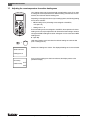
With your purchase of this Logamatic control panel you
have acquired a product that promises you easy control
over your heating system. It offers you optimum heating
convenience and minimum energy consumption.
The control panel enables you to operate your heating
system so that you can combine your economical and
ecological aspirations. Of course your personal comfort
is always the priority.
The control panel, which is controlled by the MEC2
remote control, is set up at the factory for immediate
use. Naturally, you or your heating contractor can modify
these default settings and adapt them to your individual
requirements.
The MEC2 remote control is the central control.
Some functions that you may need are located behind a
flap. The buttons behind this flap enable you to make
various adjustments.
The control concept is:
"Push and turn"
"The control speaks your language."
Your heating system offers a wealth of other useful
functions. Some examples of these are:
– Automatic warm weather shut down (WWSD)
– Party/pause function
– Vacation function
– DHW heating at the touch of a button
4
Logamatic 4323 - Technical specifications are subject to change without prior notice.
What you should know about your heating system
2
2
What you should know about your heating system
Why should you become more familiar with your
heating system?
Modern heating systems offer you many functions for
saving energy without sacrificing comfort. Getting to
know this heating technology may seem daunting at
first, but after a short while you will recognize the
advantages you can gain from a heating system that is
set up to meet your personal requirements. The more
you are aware of the options offered by your heating
system, the more advantage you will be able to take of
them.
How does your heating system work?
Your heating system comprises the boiler with burner,
the heating control panel, the piping and the radiators or
radiation of some type. A DHW storage tank or an
instantaneous water heater heats the water required for
shower, bath or washing your hands. Depending on the
way your heating system has been installed, it can
operate either purely as a central heating system or
together with a DHW storage tank. It is important that the
various components match each other. The burner
combusts fuel (e.g. gas or oil) and heats the water inside
the boiler. Using pumps, this hot water is transported
through the piping to the consumers (radiators, radiant
heating system, etc).
Logamatic 4323 - Technical specifications are subject to change without prior notice.
5
2
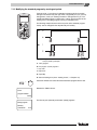
What you should know about your heating system
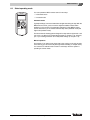
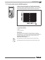
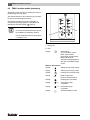
Fig. 1 shows the heating circuit of a pumped central
heating system: The burner [2] heats the water inside
the boiler [1]. This boiler water is transported by the
pump [3] through the system supply pipe [4] to the
radiators [6]. The boiler water flows through the
radiators, and in doing so, gives off some of its heat. The
boiler water flows back to the boiler via the return line [7],
where the cycle starts again.
The room temperature can be adjusted to your personal
requirements using the radiator valves [5]. All radiators
are supplied with the same supply temperature. The
heat transferred to the room depends on the radiator
surface and the boiler water throughput. Therefore, the
heat transfer can be manipulated via the radiator valves.
Fig. 1
Pumped central heating design
1
Boiler
2
Burner
3
Pump
4
System supply pipe
5
Radiator valves
6
Radiators
7
System return pipe
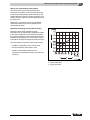
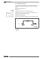
What determines the heat demand of a room?
The heat demand of a room largely depends on the
following factors:
– Outdoor temperature
– Desired room temperature
– Type of construction/insulation of the building
– Wind factor
– Solar gain
– Internal heat sources
(open fireplace, occupants, lamps, etc.)
– Closed or open windows
You should take these factors into consideration to
achieve a comfortable room temperature.
6
Fig. 2
Influences on the room climate
Logamatic 4323 - Technical specifications are subject to change without prior notice.
What you should know about your heating system
2
Why do you need a heating control panel?
The control panel ensures convenient heat and
economical consumption of fuel and electrical energy.
It switches the heat generator (boiler and burner) and
pumps ON if warm rooms or hot water are desired. In so
doing, it uses the components of your heating system at
the correct time.
Furthermore, your heating system records different
variables that influence the room temperature and
compensates for these.
What does the heating control panel calculate?
Advanced control panels calculate the boiler
temperature (the so-called supply temperature) subject
to the outdoor temperature. The relationship between
the outdoor temperature and the supply temperature is
described as the heating curve. The lower the outdoor
temperature, the higher the supply temperature must be.
The control panel can operate in three control modes:
– Weather-compensated control (outdoor reset)
– Room temperature control (indoor reset)
– Weather-compensated control with room
temperature compensation (outdoor reset with room
influence)
Fig. 3
Heating zone curve (example)
x
Outdoor temperature
y
Supply temperature
Logamatic 4323 - Technical specifications are subject to change without prior notice.
7
2
What you should know about your heating system
Weather-compensated control (outdoor reset)
With weather-compensated control, only the outdoor
temperature captured by the outdoor temperature
sensor is decisive for the supply temperature. Room
temperature fluctuations through radiant energy from
the sun, occupants, open fireplaces or similar external
heat sources are not considered.
If you use this type of control, adjust the radiator valves
(if equipped) so that the desired room temperature is
achieved in the different rooms.
Room temperature-dependent control (indoor reset)
Another possible heating control method is room
temperature-dependent control. The control panel
calculates the supply temperature based on the set and
actual room temperatures.
To be able to use the room temperature control, you
need a room that is representative of your whole home.
All factors influencing the temperature in this "reference
room" – where the user interface is located – will also
apply to all other rooms. Not every home has a room that
meets these requirements. Pure room temperaturedependent control has certain limitations in such cases.
Should you, for example, open a window in the room
where the room temperature is measured, the control
panel will "think" that you have opened the windows in
every room in your house and will begin to heat
vigorously.
Or the reverse might apply: You measure the
temperature in a south-facing room with different heat
sources (solar or other heat sources, e.g. an open
fireplace). Now the control panel "thinks" that it is as hot
in every room as in the reference room; consequently
the boiler output will be severely reduced so that, for
example, the north-facing rooms will become too cold.
Weather-compensated control with room
temperature compensation (outdoor reset with
room influence)
Weather-compensated control with room temperature
compensation combines the advantages of the other
two control modes. The desired supply temperature,
which is subject mainly to the outdoor temperature, can
be adjusted by the room temperature to only a limited
degree. This achieves improved maintenance of the
room temperature within the room containing the user
interface without completely ignoring the other rooms.
With this kind of control you will also need to keep all
radiator valves (if equipped) in the reference room fully
open.
Why do the radiator valves have to stay fully open?
If, for example, you want to reduce the room
temperature in the reference room, and you therefore
close the radiator valve further, the supply rate through
the radiator is reduced and, therefore, less heat is
transferred to the room. This reduces the room
temperature. The heating control panel will try to
counteract the sinking room temperature by raising the
supply temperature. However, raising the supply
temperature will not raise the room temperature since
the radiator valve continues to limit the room
temperature.
A supply temperature that is too high results in
unnecessary heat losses in boiler and piping. At the
same time, the temperature in all rooms without
radiator valves increases due to the higher boiler water
temperature.
With this kind of control you always need to keep all
radiator valves (if equipped) in the reference room fully
open.
8
Logamatic 4323 - Technical specifications are subject to change without prior notice.
What you should know about your heating system
2
Why do I need a timer?
What are heating zones?
Advanced heating systems are equipped with a timer to
save energy. With a timer, you can set up an automatic
changeover between two different room temperatures,
subject to time. This enables you to set a reduced room
temperature at night, or at other times when a reduced
temperature is sufficient, while operating your heating
system with the standard room temperature during the
day.
A heating zone describes the circuit made by the boiler
water from the boiler via the radiators and back again
(Æ Fig. 1, page 6). A simple heating zone comprises a
heat source, a supply pipe, a radiator and a return pipe.
A pump installed in the piping circulates the boiler
water.
You have four options for reducing the room
temperature via the control panel. Your heating
contractor will select one according to your requirements
and will set it up for you:
– Total shutdown (no room temperature control)
– Reduced room temperature (a reduced room
temperature will be maintained)
– Change between total shutdown and reduced
heating subject to room temperature
– Change between total shutdown and reduced
heating subject to outdoor temperature
With total shutdown of the heating system, no pumps
or other system components are operated. Heating only
starts up again if the heating system is at risk of freezing.
Several heating zones may be connected to one boiler,
for example, one heating zone for supplying radiators
and another zone for supplying a radiant floor heating
system. In this case, the radiators are supplied at a
higher supply temperature than the radiant floor
heating system.
The supply of different supply temperatures to different
heating zones can be achieved by e.g. installing a
three-way mixing valve between the heat source and
the radiant floor heating system.
Using an additional temperature sensor in the supply of
the heating zone to be supplied, sufficient cold return
water is mixed via a three-way mixing valve into the hot
supply water to achieve the desired lower temperature.
It is important to note that heating zones with three-way
mixing valves require an additional pump. This pump
enables the second heating zone to be operated
independently of the first heating zone.
Heating with reduced room temperature (night mode)
only differs from standard heating mode (day mode)
through a lower supply temperature.
When changing from total shutdown to reduced
heating, the boiler will remain shut down as long as the
room temperature exceeds a set level. This function is
only available if a room temperature sensor is installed.
When changing from total shutdown to reduced
heating, the boiler will remain shut down as long as the
outdoor temperature exceeds a preset level.
Logamatic 4323 - Technical specifications are subject to change without prior notice.
9
3
3
Tips on energy-efficient heating
Tips on energy-efficient heating
Here are a few tips on how to heat economically without
sacrificing convenience:
z Only heat if you need warmth. Use the preset heating
programs (standard programs) in the control panel or
those that have been tailored to your individual
requirements.
z Air rooms properly during the heating season:
Open windows fully three to four times a day for
approx. 5 minutes. Having the window slightly open
all the time does not provide fresh air changes and
wastes valuable energy.
z Close the radiator valves while ventilating.
z Windows and doors are places where a lot of heat
is lost. Therefore, check whether the doors and
windows are sealed correctly. Close shutters
(if installed) at night.
z Never position large objects such as a sofa or a desk
immediately in front of the radiators (maintain a
clearance of at least 20" (0.50 m). Otherwise, the
heated air cannot circulate and heat the room
adequately.
z In rooms you occupy during the day, you can, for
example, set a room temperature of 70 °F (21 °C),
while 63 °F (17 °C) may be sufficient at night.
To achieve this, use the standard heating mode
(day mode) and the setback mode (night mode,
Æ Chapter 6).
z Never overheat rooms; overheated rooms are
unhealthy, plus they waste money and energy. If you
reduce the day room temperature, for example from
70 °F (21 °C) to 68 °F (20 °C), you can save approx.
six percent of your heating bill.
z Also heat in an energy-conscious manner in spring
and autumn, and use the automatic warm weather
shut down (Æ Chapter 7).
z A pleasant room climate depends not only on the
room temperature, but also on the relative humidity.
The drier a room, the cooler it feels. You can optimize
the relative humidity with house plants.
z You can also save money when heating DHW:
Only operate the recirculation pump via a timer.
Research has shown that it is generally sufficient to
run the recirculation pump for only three minutes
every half hour.
z Arrange with your local heating contractor to have
your heating system serviced annually.
10
Logamatic 4323 - Technical specifications are subject to change without prior notice.
Safety
4
Safety
4.1
About this manual
These operating instructions contain important
information regarding the safe and correct operation of
the Logamatic 4323 control panel.
4.2
RISK OF INJURY/
SYSTEM DAMAGE
CAUTION!
Intended use
Tip for optimum use of equipment and
adjustment as well as useful information.
4.5
Standards, regulations and directives
USER NOTE
Observe all regulations and standards
applicable to installation and operation of
the system in your country.
USER NOTE
All electrical components must be
approved in the USA and Canada!
Please observe these notes
z Only operate the control panel as intended and if it is
in perfect working order.
z The technician must give detailed instructions on the
operation of the system.
z Please read these operating instructions carefully.
z Only the operating characteristics listed in this
manual may be input and modified. Other entries
alter the control programs of the heating system and
can lead to incorrect system functions.
z Maintenance, repairs and fault diagnosis must be
carried out by trained technicians only.
RISK OF LIFE
This product has been tested and certified
and meets applicable standards for the
US and Canadian markets.
due to electric shock!
WARNING!
4.4
Key to symbols
Two levels of danger are identified and signified by the
following terms:
RISK OF LIFE
WARNING!
Indicates a potentially dangerous situation
that could cause minor or moderately
serious injuries or damage to property.
USER NOTE
The Logamatic 4323 control panel is designed to control
and monitor heating systems with different types of
boilers in apartment buildings, residential developments
and buildings with medium to large heat demand.
4.3
4
z Never open the control panel.
z In an emergency, switch off the control
panel (e.g. with the heating system
emergency shut-off switch) or isolate
the heating system from the power
supply by disengaging the heating
system circuit breaker.
z Arrange for your heating contractor to
rectify any heating system faults
immediately.
Identifies possible dangers emanating
from a product, which might cause serious
injury or death if appropriate care is not
taken.
Logamatic 4323 - Technical specifications are subject to change without prior notice.
11
4
Safety
4.7
RISK OF INJURY/
SYSTEM DAMAGE
CAUTION!
Disposal
due to operator error!
z Dispose of the control panel packaging in an
environmentally-responsible manner.
Operator errors can cause injury and
damage to property.
z The lithium battery in the CM431 module must be
replaced by a heating contractor only.
z Make sure that children never operate
the appliance unsupervised or play
with it.
z Make sure that only personnel trained
to operate the appliance correctly have
access to it.
RISK OF SCALDING
from hot water.
WARNING!
During thermal disinfection the entire DHW
system is factory-set to be heated to
158 °F (70 °C) (start time: Tuesday night
at 1:00 am (01:00 h)). Hot water
temperatures above 122 °F (50 °C) can
cause scalding almost immediately.
z The default start time can be changed
to another time by a heating contractor
if desired (shift work).
z If thermal disinfection is activated,
ensure that a thermostatic tempering
valve is installed as protection against
scalding.
SYSTEM DAMAGE
CAUTION!
from frost.
The heating system can freeze up in cold
weather if it is switched off.
z Protect your heating system against
frost damage by draining it and the
DHW piping at the lowest possible
point.
4.6
Cleaning the control panel
z Clean the control panel with a damp cloth only.
12
Logamatic 4323 - Technical specifications are subject to change without prior notice.
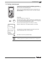
Controls and MEC2 remote control
5
Controls and MEC2 remote control
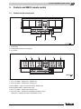
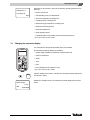
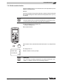
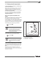
5.1
Controls on the control panel
Fig. 4
Logamatic 4323 control panel (standard delivery)
1
On/Off switch
2
Connection for external service equipment
3
L1, L2 fuses
Fig. 5
5
Installed modules (possible full complement)
1
Slot 1: e.g. FM442 – heating zone 1, heating zone 2
2
Slot 2: e.g. FM442 – heating zone 3, heating zone 4
A Slot A: ZM433 – supply for external heat sources, heating zone 0
B Slot B: MEC2 (CM431) – MEC2 remote control
3
Slot 3: e.g. FM442 – heating zone 5, heating zone 6
4
Slot 4: e.g. FM441 – heating zone 7 DHW/DHW recirculation pump or
heating zone 7, heating zone 8 (with module FM442 in slot 4)
Logamatic 4323 - Technical specifications are subject to change without prior notice.
13
5
5.2
Controls and MEC2 remote control
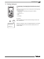
MEC2 remote control
The MEC2 remote control is the central element used to
operate the Logamatic 4323 control panel.
Display
The display (Æ Fig. 6, [4]) indicates functions and
operating values, e.g. the actual room temperature.
Dial
4
The dial (Æ Fig. 6, [5]) is used to set new values and
scroll through the menus.
3
Buttons
2
You control the functions via the buttons, and the
relevant indications appear on the display. To change a
value push and hold the button, then turn the dial.
1
Behind a flap (Æ Fig. 6, [7]) further buttons are available
for further settings, e.g. for entering week days or setting
the time.
The unit automatically returns to the standard display if
no entry is detected for some time.
14
6
7
When the button is released, the new value is
implemented and saved.
You can reach certain functions, such as day room
temperature, night room temperature, and possibly the
DHW temperature or the automatic heating mode,
directly via the corresponding buttons (Æ Fig. 6, [1] to [3]
and [6]).
5
Fig. 6
MEC2 remote control
1
Continuously reduced heating mode
2
Automatic heating mode by program
3
Continuous heating mode
4
Display
5
Dial
6
Input DHW temperature/heating
7
Flap for the keypad of control level 2
Logamatic 4323 - Technical specifications are subject to change without prior notice.
Controls and MEC2 remote control
5
The central MEC2 remote control
Fig. 7
MEC2 remote control
1
Display
9
Display for set nominal room temperature
2
Dial
10 Input DHW temperature/heating
3
Continuous heating mode
11 Set the time
4
Automatic heating mode by program
12 Change temperature values
5
Continuously reduced heating mode
13 Set warm weather shut down (WWSD) temperature
6
Set day
14 Back to standard display
7
Set vacation days
15 Select a timer program
8
Select standard display
16 Select heating zones/DHW zone
Logamatic 4323 - Technical specifications are subject to change without prior notice.
15
5
5.3
Controls and MEC2 remote control
Switching on the control panel
z Check that the control panel ON/OFF switch
(Æ Fig. 8, [1]) and the manual switches on the
installed modules (Æ Fig. 8, [2]) are set to "I" and
"AUT".
z Switch the control panel ON by setting the ON/OFF
switch to "I" (Æ Fig. 8, [1]).
After approx. 2 minutes all modules installed in the
control panel are recognized and the standard display is
shown.
Fig. 8
5.4
On/Off switch
1
On/Off switch
2
Manual switches on the module
Switching off the control panel
z Switch the control panel OFF by setting the ON/OFF
switch to "0" (Æ Fig. 8, [1]).
z In an emergency: Isolate the heating system from the
mains supply with the emergency shut-off switch
outside the boiler room or by disengaging the heating
system circuit breaker.
16
Logamatic 4323 - Technical specifications are subject to change without prior notice.
Basic functions
6
6
Basic functions
In this chapter you will find information about the standard functions of the MEC2
remote control and their use. The standard functions are:
– Select the operating mode
– Set the room temperature
– Set the DHW temperature
– Load DHW once
6.1
Simple operation
The standard functions are controlled by pressing one of the buttons on the
"Standard functions" keypad or by turning the dial.
AUT
Example: Adjusting the room temperature for day mode
Press "Day mode" to select the standard heating mode (day mode). The LED of
the "Day mode" button lights up; day mode is enabled.
Set the desired room temperature by turning the dial.
(Condition: For this, the user interface flap must be closed.)
The display shows the set value.
room temp set
70°F
day mode always
Logamatic 4323 - Technical specifications are subject to change without prior notice.
17
6
Basic functions
USER NOTE
If your heating system is equipped with several heating zones, you must first
select the correct heating zone (Æ Chapter 7.6). Only then can you select the
operating mode and room temperature.
USER NOTE
The following MEC2 displays covers the available screens:
– of module ZM433 (standard equipment),
– of the most frequently-used modules FM441 and FM442 (accessories).
Depending on the way your heating contractor has configured your system, one
or more MEC2 screens may not appear, although the above modules are
installed in your control panel.
Detailed descriptions of MEC2 screens for other modules are included in the
corresponding module documentation.
6.2
Permanent display
There are two different permanent displays. Either one of the factory-set
permanent displays is shown, depending on whether the MEC2 is installed in the
control panel or is installed as a wall-mounted unit.
Factory-set permanent display if the MEC2 is installed in the control panel.
system supply
113°F
outdoor temp
70°F
Factory-set permanent display if the MEC2 is installed as a wall-mounted unit.
room temp
67°F
outdoor temp
32°F
18
Logamatic 4323 - Technical specifications are subject to change without prior notice.
Basic functions
6.3
6
Select operating mode
You can operate the MEC2 remote control in two ways:
– in automatic mode
– in manual mode
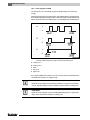
Automatic mode
AUT
Typically buildings, homes are heated less at night than during the day. With the
MEC2 remote control, you don't need to adjust the radiator valves before
bedtime or in the morning. The automatic changeover of the MEC2 remote
control does this for you. It switches between day mode (standard mode) and
night mode (setback mode).
The times when the heating system changes from day mode to night mode – and
vice-versa – are factory-set via standard programs (Æ Chapter 7.10). However,
you or your heating contractor can modify these settings (Æ Chapter 7.12).
Manual operation
For example, if you want to heat longer late in the evening or not quite as early
in the morning, you can set the day and night mode manually (Æ Chapter 6.3.2).
You can also use manual mode to heat on cooler days when the system is
operating in summer mode.
Logamatic 4323 - Technical specifications are subject to change without prior notice.
19
6
Basic functions
6.3.1 Selecting automatic mode
In automatic mode your heating system will operate with the timer program,
i.e. central and DHW heating at preset times (Æ "Why do I need a timer?",
page 9).
Example: Enabling automatic mode
AUT
Press "AUT".
The LED of the AUT button is on; automatic mode is active.
In addition, either the "Day mode" or "Night mode" LED will light up. This is
subject to the set times for day and night mode.
room temp set
70°F
automatic day
Automatic day and night mode
At fixed times, central heating is provided or the room temperature is set back.
Fig. 9
20
Changeover from day and night mode at fixed times (example)
1
Day mode
2
Night mode
Logamatic 4323 - Technical specifications are subject to change without prior notice.
Basic functions
6
6.3.2 Selecting manual mode
Press either "Day mode" or "Night mode" to change to manual mode.
Press "Day mode".
The LED of the day mode button lights up. Now your heating system is in
constant day mode (standard mode).
room temp set
70°F
day mode always
Press "Night mode".
room temp set
63°F
The LED of the night mode button lights up. Now your heating system is in
constant night mode (setback heating mode), and operates at a lower room
temperature.
night mode alwys
USER NOTE
If you have selected manual mode, other automatic controls will also be
switched off, e.g. warm weather shut down (WWSD) (Æ Chapter 7.13).
Logamatic 4323 - Technical specifications are subject to change without prior notice.
21
6
6.4
Basic functions
Set the room temperature
With the flap closed you can adjust the room temperature with the dial. With the
flap open, also press "Day mode" or "Night mode".
With the dial, you can select the room temperature in degree steps between
52 °F (11 °C) (day), or 36 °F (2 °C) (night), and 86 °F (30 °C). The set
temperature is displayed via an LED next to the dial. For temperatures below
59 °F (15 °C) or above 77 °F (25 °C), the "–" or "+" LED illuminates.
AUT
The factory setting for the day room temperature is 70 °F (21 °C).
The factory setting for the night room temperature is 63 °F (17 °C).
Any adjustment applies to all heating zones allocated to the MEC2 remote
control (Æ Chapter 7.7).
USER NOTE
The set room temperature applies to the currently active heating mode, i.e. day
or night mode. You will recognize if the currently-active heating mode is ON
depending on whether or not the green LED is lit up.
6.4.1 For the current operating mode
You are currently in automatic "Day mode" and would like to change the room
temperature.
(Condition: For this, the user interface flap must be closed.)
Turn the dial to the desired day room temperature (here: "73°F" (23 °C)).
The day room temperature is now adjusted to 73 °F (23 °C). The selected
permanent display will then appear again.
room temp set
73°F
automatic day
22
Logamatic 4323 - Technical specifications are subject to change without prior notice.
Basic functions
6
6.4.2 For the operating mode not currently enabled
You may also adjust the room temperature for an operating mode that is
currently inactive.
For example, you are currently in automatic day mode and would like to change
the set night temperature.
Hold down "Night mode" and select the desired night room temperature with the
dial (here: "61°F" (16 °C)).
+
Release the "Night mode" button.
room temp set
61°F
The selected night temperature is now set to 61 °F (16 °C). The selected
permanent display will then appear again.
night mode alwys
AUT
Press "AUT".
The "AUT" LED lights up; automatic mode is re-enabled.
USER NOTE
If you are currently in automatic night mode, and you wish to adjust the day
mode, proceed as described above, but instead hold down "Day mode".
Logamatic 4323 - Technical specifications are subject to change without prior notice.
23
6
Basic functions
6.5
DHW heating
The user interface also offers you the option of heating DHW in an energyconscious manner. For this purpose, DHW heating can be selected via a timer.
You can select between the set values for DHW and "OFF" to stop DHW
heating.
To save energy, DHW heating will be switched off outside the programmed
times, i.e. DHW is not heated in night mode.
DHW heating is factory-set to 140 °F (60 °C) in automatic mode.
Fig. 10
Example: DHW heating
1
Day mode
2
Night mode
3
OFF
We recommend heating the DHW storage tank once in the morning,
before central heating begins, and reheating once in the evening if necessary
(Æ Fig. 10).
USER NOTE
The DHW temperature has fallen below the set value if the green "DHW" LED
lights up.
24
Logamatic 4323 - Technical specifications are subject to change without prior notice.
Basic functions
6
6.5.1 Setting the hot water temperature
RISK OF SCALDING
from hot water.
WARNING!
Hot water temperatures above 122 °F (50°C) can cause scalding almost
immediately.
z Do not draw off DHW unmixed.
z Ensure that a thermostatic tempering valve is installed as protection
against scalding.
You can change the DHW temperature:
Hold the "DHW" button down and select the desired DHW temperature with the
dial.
+
Release the "DHW" button. The newly-selected DHW temperature is saved
within approx. 2 seconds. The permanent display will then appear again.
DHW
set
140°F
USER NOTE
During thermal disinfection, DHW will be heated to at least 140 °F (60 °C) once
or twice per week to kill off possible bacteria (e.g. legionella).
Logamatic 4323 - Technical specifications are subject to change without prior notice.
25
6
Basic functions
6.5.2 Single DHW charging
If the "DHW" LED lights up, only a limited amount of hot water remains in the
storage tank. Should you require a larger amount of DHW, proceed as follows:
Press "DHW".
The "DHW" LED flashes, and a single DHW charge is started.
DHW
actual
131°F
Depending on the size of the storage tank and the boiler output, DHW will be
available after approx. 10 to 30 minutes. With instantaneous water heaters or
combination boilers, DHW will be available almost immediately.
reloading
26
Logamatic 4323 - Technical specifications are subject to change without prior notice.
Extended functions
7
7
Extended functions
The extended functions are explained in this chapter. You need the extended
functions to be able to change the factory settings of your heating system. You
may use the following functions:
– Display the current operating values of your heating system
– Set the time
– Set date
– Adjust heating zones
– Select a heating program
– Set the room temperature for additional heating zones
The buttons for the extended functions are located behind the flap of the MEC2
remote control.
7.1
Buttons for extended functions
4
1
5
2
6
3
7
9
8
7 747 012 073-01.1RS
Fig. 11
Buttons for the extended functions
1
Set day
2
Set vacation days
3
Select standard display
4
Set the time
5
Change temperature values
6
Set warm weather shut down (WWSD) temperature
7
Back to standard display
8
Select a timer program
9
Select heating zones/DHW zone
Logamatic 4323 - Technical specifications are subject to change without prior notice.
27
7
7.2
Extended functions
Controlling the extended functions
The extended functions provide access to an additional control level. At this
level, proceed according to the "Push and turn" principle. The control procedure
is always similar:
z Open flap.
+
Hold the desired button down, e.g. the "Time" button, and simultaneously turn
the dial.
By turning the dial, you modify the values that flash on the display.
Release the button. Modified values are saved.
"Back" button = Exit menu.
7.3
Displaying operating values
You can display and control the various operating values of the boiler, of the
selected heating zone, and the system.
Only the operating values of the selected heating zone, e.g. heating zone 0, are
displayed (Æ Chapter 7.6).
z Open flap.
Turn the dial clockwise without pressing any other button.
28
Logamatic 4323 - Technical specifications are subject to change without prior notice.
Extended functions
7
Depending on the modules, various of the following operating displays can be
called up:
heating zone 0
– Burner and run time
room temp set
68°F
– Actual heating zone room temperature
– Set room temperature of heating zone
– Operating status of heating zone
– Measured supply temperature of heating zone
– Measured DHW temperature*
– Set DHW temperature*
– DHW operating mode*
– Operating status of recirculation pump and tank primary pump*
* Only if a DHW module has been installed.
7.4
Changing the permanent display
You can determine the permanent display of the user interface.
The following permanent displays are available:
– System supply (if MEC2 is installed as a wall-mounted unit)
– Outdoor temperature
– DHW*
– Time
– Date
– Room temperature (if installed in room)
* Only if a DHW module has been installed.
+
system supply
113°F
date
08/20/2009
Hold the "Display" button down, and select the desired permanent display with
the dial (here: "date").
Release the "Display" button. The selected permanent display has now been
saved.
Logamatic 4323 - Technical specifications are subject to change without prior notice.
29
7
7.5
Extended functions
Setting the date and time
USER NOTE
Date and time are preset at the factory. This function is backed up by battery
power independent of the mains power supply.
Setting the date
Hold "Weekday" down, and select the desired date with the dial (here: "20").
+
The name of the day automatically changes (here "Monday") if you set the date
using the dial (here "20").
set date
08/20/2009
Release "Weekday" to save your input.
Monday
Press "Weekday" again to enter the month.
Press "Weekday" again to enter the year.
The item flashing can be modified with the dial.
Setting the time
Hold down "Time" and select the desired time with the dial.
+
The time is set in one-minute steps.
set time
03:52:58pm
30
Release "Time" to save your input.
Logamatic 4323 - Technical specifications are subject to change without prior notice.
Extended functions
7.6
7
Selecting a heating zone
Your heating system may be equipped with several heating zones. If you want
to change a setting, e.g. the heating program, first select the desired heating
zone.
Depending on the equipment level of your heating system, the following heating
zones can be selected:
– MEC2 heating zones (all heating zones assigned to the MEC2,
Æ Chapter 7.8)
– Heating zone 0 – 8
– DHW
– Recirculation
z Open flap.
+
Hold down "Heating zone" and select the desired heating zone with the dial
(here: "heating zone 2").
Release the "Heating zone" button. The displayed heating zone is now selected.
select heat zone
heating zone 2
As soon as the heating zone has been selected, the display returns to the
permanent display.
Logamatic 4323 - Technical specifications are subject to change without prior notice.
31
7
7.7
Extended functions
Adjusting the room temperature for another heating zone
Your heating system may be equipped with several heating zones. If you want
to change the room temperature for a different heating zone than the one last
selected, first select the desired heating zone.
Depending on the equipment level of your heating system, the following heating
zones can be selected:
– MEC2 heating zones (all heating zones assigned to the MEC2,
Æ Chapter 7.8)
AUT
– Heating zone 0 – 8
If several heating zones are assigned to the MEC2, the temperature for these
heating zones can only be adjusted for all. Otherwise a fault message "selection
not supported MEC heatingzones select" will appear. In such cases select "MEC
heatingzones".
z Open flap.
Hold down "Heating zone" and select the desired heating zone with the dial
(here: "heating zone 2").
+
Release the "Heating zone" button. The displayed heating zone is now selected.
select heat zone
heating zone 2
As soon as the heating zone has been selected, the display returns to the
permanent display.
room temp
67°F
outdoor temp
32°F
32
Logamatic 4323 - Technical specifications are subject to change without prior notice.
Extended functions
7
Press and hold down "Temp". First, the selected heating zone is displayed. After
approx. 2 seconds, the display will show the currently-selected temperature and
operating mode.
+
Adjust the temperature for the heating zone with the dial (here: "70°F" (21 °C)).
Release the button to save your input.
room temp set
70°F
The day room temperature is now adjusted to 70 °F (21 °C). The selected
permanent display will then appear again.
automatic day
USER NOTE
If you want the adjust the temperature for an operating mode that is not the
current mode, first select the corresponding operating mode (e.g. by pressing
"Night mode"). After changing the temperature, reset the operating mode to the
previous setting.
USER NOTE
For heating zones with individual remote controls (e.g. BFU), you can adjust
the room temperature only via this remote control (Æ instructions for the
relevant remote control).
Logamatic 4323 - Technical specifications are subject to change without prior notice.
33
7
7.8
Extended functions
Heating zones with MEC2 remote control
During installation, your heating contractor will determine which heating zones
are to be controlled by the MEC2 remote control. These heating zones are called
"MEC heatingzones".
MEC heatingzones
The following adjustments made at the MEC2 apply to all "MEC heatingzones"
simultaneously:
– Set the room temperature
– Set warm weather shut down (WWSD) temperature
– Select operating mode
– Set the vacation function
– Set the party or pause function
selection
not supported
MEC heatingzones
select
If you have selected an individual heating zone that is assigned to the MEC2,
and you want to make one of the above adjustments, the fault message
"selection not supported MEC heatingzones select" will appear.
Select "MEC heatingzones" to program these settings (Æ Chapter 7.6).
Individual heating zones
The following adjustments can only be implemented for each individual heating
zone separately:
– Select the standard program
– Change the standard program by moving set points
– Insert or delete set points
– Delete or connect heating phases
– Create a heating, DHW or recirculation pump program
timer
not supported
primary zone
select
34
If you have selected "MEC heatingzones" and you want to make one of the
above adjustments, the fault message "timer not supported primary zone select"
will appear.
Enter these settings for each heating zone separately (Æ Chapter 7.6).
Logamatic 4323 - Technical specifications are subject to change without prior notice.
Extended functions
7.9
7
Selecting and modifying a heating program
7.9.1 What is a heating program?
A heating program automatically switches the operating mode (day and night
mode) at fixed times. This automatic changeover is effected via a timer.
Before you use this option, consider the following:
– At what time in the morning should your home be warm? Does this time vary
depending on the day of the week?
– Are there days when you do not need your home to be heated during the
day?
– From what time in the evening does your home no longer need to be heated?
This too may vary depending on the day of the week.
It may vary how long it takes your heating system to heat up individual rooms.
This will be subject to the outdoor temperature, the building insulation and the
drop in room temperature.
The "optimization" function of the user interface calculates the various heat-up
times. Ask your heating contractor whether this function has been enabled. If so,
all you need to do is enter the times at which your home should be warm.
With the user interface, Buderus offers eight different, preset heating programs
as standard programs.
Fig. 12
Example for a standard program (here: "family program" from Monday to
Thursday)
1
Day mode
2
Night mode
USER NOTE
After commissioning, check whether the selected heating program suits your
lifestyle. If not, several options are available for matching the heating program
to your individual requirements.
Logamatic 4323 - Technical specifications are subject to change without prior notice.
35
7
Extended functions
7.9.2 Timer program for DHW
You may enter your own heating program for DHW heating. This saves you
energy.
Determine the time points so that DHW is only available when one heating zone
is in standard heating mode (day mode). In this case, DHW is heated 30 minutes
before day mode of the first heating zone, so it is available at the selected time.
Fig. 13
DHW heating begins 30 minutes before day mode of the first heating zone,
and ends with the beginning of night mode of the last heating zone.
A Heating zone 1
B Heating zone 2
C DHW
1
Day mode
2
Night mode
If you require additional hot water, you may, at short notice, heat DHW with the
"ext DHW load" function (Æ Chapter 6.5.2).
USER NOTE
DHW will not be subject to a temperature setback if you operate one heating
zone in "day mode always" mode, and DHW is being heated by "heating zone".
USER NOTE
DHW will not be heated if you are operating all heating zones in "night mode
alwys" mode and DHW is heated by "heating zone".
36
Logamatic 4323 - Technical specifications are subject to change without prior notice.
Extended functions
7
7.10 Selecting a standard program
The MEC2 remote control is equipped with eight different, preset heating
programs that act as standard programs. See the following page for a summary
of the preset times of the standard programs.
Please check which standard program best meets your requirements. First
check the number of set points, and then the times. The "family" program is
preset at the factory.
z Open flap.
z Select a heating zone (Æ Chapter 7.6).
Press and hold down "PROG". Initially the heating zone is displayed for which
you want to select a standard program. Approx. 2 seconds later the designation
of the currently-selected standard program will appear.
+
Select the desired standard program with the dial (here: "seniors").
Release the "PROG" button. The displayed program is now selected.
timer
program selction
seniors
seniors' program
Monday
at 05:30am
The display shows the program designation and the first set point for the
selected heating program (here: "seniors' program").
70°F
Press "Back" to return to the permanent display.
USER NOTE
Switching programs are only effective in automatic mode (Æ Chapter 6.3.1).
Logamatic 4323 - Technical specifications are subject to change without prior notice.
37
7
Extended functions
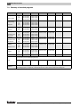
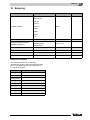
7.11 Summary of standard programs
Program name
Day of week
ON
OFF
Mo – Th
Fr
Sat
Sun
5:30 am (05:30)
5:30 am (05:30)
6:30 am (06:30)
7:00 am (07:00)
10:00 pm (22:00)
11:00 pm (23:00)
11:30 pm (23:30)
10:00 pm (22:00)
Mo – Th
Fr
Sat
Sun
4:30 am (04:30)
4:30 am (04:30)
6:30 am (06:30)
7:00 am (07:00)
10:00 pm (22:00)
11:00 pm (23:00)
11:30 pm (23:30)
10:00 pm (22:00)
Mo – Fr
Sat
Sun
6:30 am (06:30) 11:00 pm (23:00)
6:30 am (06:30) 11:30 pm (23:30)
7:00 am (07:00) 11:00 pm (23:00)
Mo – Th
Fr
Sat
Sun
5:30 am (05:30) 8:30 am (08:30) 12:00 am (12:00) 10:00 pm (22:00)
5:30 am (05:30) 8:30 am (08:30) 12:00 am (12:00) 11:00 pm (23:00)
6:30 am (06:30) 11:30 pm (23:30)
7:00 am (07:00) 10:00 pm (22:00)
Mo – Th
Fr
Sat
Sun
6:00 am (06:00)
6:00 am (06:00)
6:30 am (06:30)
7:00 am (07:00)
Mo – Th
Fr
Sat
Sun
6:00 am (06:00) 8:00 am (08:00) 11:30 am (11:30) 1:00 pm (13:00) 5:00 pm (17:00) 10:00 pm (22:00)
6:00 am (06:00) 8:00 am (08:00) 11:30 am (11:30) 11:00 pm (23:00)
6:00 am (06:00) 11:00 pm (23:00)
7:00 am (07:00) 10:00 pm (22:00)
"singles"
Mo – Th
Fr
Sat
Sun
6:00 am (06:00) 8:00 am (08:00)
6:00 am (06:00) 8:00 am (08:00)
7:00 am (07:00) 11:30 pm (23:30)
8:00 am (08:00) 10:00 pm (22:00)
"seniors"
Mo – Su
5:30 am (05:30) 10:00 pm (22:00)
"family"
Factory setting
"early morning"
Early shift
"evening"
Late shift
"morning"
Part-time work in
the morning
"afternoon"
Part-time work in
the afternoon
"midday"
Midday at home
11:30 am (11:30)
11:30 am (11:30)
11:30 pm (23:30)
10:00 pm (22:00)
ON
4:00 pm (16:00)
3:00 pm (15:00)
4:00 pm (16:00)
3:00 pm (15:00)
OFF
ON
OFF
10:00 pm (22:00)
11:00 pm (23:00)
10:00 pm (22:00)
11:00 pm (23:00)
You can enter your own individual program here:
"new"
"custom 1"
Tab. 1
38
If none of the standard programs suit you, you may change them, have them changed by your heating contractor, or enter a
new heating program (Æ Chapter 8.2). This will be saved under "custom" and the number of the heating zone.
Standard programs ("ON" = day mode, "OFF" = night mode)
Logamatic 4323 - Technical specifications are subject to change without prior notice.
Extended functions
7
7.12 Modifying the standard program by moving set points
If the set points, i.e. the times of a standard program at which the system
changes over between day and night mode, only partially suit you, you may
change them, or ask your heating contractor to change them for you. The
modified standard program is saved under "custom" and the number of the
heating zone. The heating program memory is available for this.
The following example shows how the set points of the standard program
"family" can be changed for the days Monday to Thursday.
Fig. 14
Changing the set point from 05:30 to 06:30 am and from 10:00 (22:00 h) to
11:00 pm (23:00 h) (example)
A "family program"
B New program "custom program 2"
1
Day mode
2
Night mode
z Open flap.
z Select a heating zone (here: "heating zone 2", Æ Chapter 7.6).
Hold down "PROG" and select the desired standard program with the dial.
+
Release the "PROG" button.
Timer
program selction
family
The first set point ("Monday at 05:30am" (05:30)) appears.
family program
Monday
at 05:30am
70°F
Logamatic 4323 - Technical specifications are subject to change without prior notice.
39
7
Extended functions
Hold down "Time" and select the desired time with the dial. Example: "06:30am"
(06:30).
+
Release "Time". The newly-adjusted time for the "ON" set point is now saved.
custom program 2
Monday
at 06:30am
The modified set point will be saved under the "custom" program and the
number of the heating zone (here "2").
70°F
Continue to turn the dial until the next set point that you want to change is
displayed.
The "OFF" set point for Monday appears. Now you can modify the time for the
"OFF" set point.
+
Hold down "Time" and select the desired time with the dial. Example: "11:00pm"
(23:00).
Release "Time". The newly-adjusted time for the "OFF" set point is saved.
Next set point
Continue to turn the dial until the next set point is displayed.
The next set point (Tuesday, 5:30 am (05:30 h)) appears.
Also change the following set points to 6:30 am (06:30 h) and 11:00 pm
(23:00 h). The system will now heat from 6:30 am to 11:00 pm (06:30 h
to 23:00 h) Monday to Thursday.
Press "Back" to return to the permanent display.
USER NOTE
You can change the weekday if you press "Weekday" instead of "Time".
You can change the switching state ("ON"/"OFF") by pressing "Display"
instead of "Weekday" or "Time". The operating mode determines the switching
state: "ON" = day mode; "OFF" = night mode.
z Ensure that a stop point is associated with every start point.
The modified standard program is saved under "custom" and the number of the
heating zone.
40
Logamatic 4323 - Technical specifications are subject to change without prior notice.
Extended functions
7
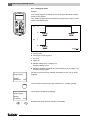
7.13 Set warm weather shut down (WWSD) temperature
In addition to the outdoor temperature, your Logamatic 4323 control panel
considers the ability of the building to store heat and its thermal insulation
(and from this creates the "Adjusted outdoor temperature", Æ Fig. 15), and after
a delay, automatically changes over between summer and winter mode.
AUT
Fig. 15
Current and adjusted outdoor temperatures compared
1
Current outdoor temperature
2
Adjusted outdoor temperature
x
Time
y
Outdoor temperature
Summer mode
If the "Adjusted outdoor temperature" exceeds the factory-set switching
threshold of 63 °F (17 °C), the heat is switched off with a delay that depends on
the storage capacity and the insulation of the building. Summer mode is
identified on the display with the
icon.
DHW heating remains operational.
Press "Day mode" if you want to heat at short notice in summer mode.
AUT
The heating system returns to automatic summer mode if you press "AUT".
Logamatic 4323 - Technical specifications are subject to change without prior notice.
41
7
Extended functions
Winter mode
DHW and central heating are operational if the "Adjusted outdoor temperature"
falls below the factory-set changeover threshold of 63 °F (17 °C).
Setting automatic warm weather shut down changeover
The desired heating zone must be selected before setting the summer/winter
time changeover. One single heating zone or all heating zones allocated to the
MEC2 can be selected.
z Select a heating zone (Æ Chapter 7.6).
Example: Heating zone 2
Setting the changeover temperature
Hold down "Su/Wi". The display briefly shows the heating zone. Then turn
the dial to the desired changeover temperature, below which you want to heat
(here: "64°F" (18°C)).
+
The display shows the set changeover temperature.
summer / winter
Release "Su/Wi" to save your input.
strt WWSD
64°F
Setting continuous summer mode
z Select a heating zone (Æ Chapter 7.6).
Example: Heating zone 2
+
Hold down "Su/Wi". The display briefly shows the heating zone. Then turn the
dial to a changeover temperature below 50 °F (10 °C).
The display shows "summr mode alwys".
summer / winter
Release "Su/Wi" to save your input.
Your heating system will constantly operate in summer mode.
summr mode alwys
Setting continuous winter mode
z Select a heating zone (Æ Chapter 7.6).
Example: Heating zone 2
+
Hold down "Su/Wi". The display briefly shows the heating zone. Then turn the
dial to a changeover temperature above 86 °F (30 °C).
The display shows "wintr mode alwys".
summer / winter
Release "Su/Wi" to save your input.Your heating system operates continuously
in winter mode.
wintr mode alwys
42
Logamatic 4323 - Technical specifications are subject to change without prior notice.
Extended functions
7
7.14 Setting the DHW operating mode
This allows you to change the DHW temperature in the DHW storage tank.
AUT
z Open flap.
Hold down "Heating zone" and select "DHW" with the dial.
+
Release the "Heating zone" button.
select heat zone
DHW
Then the permanent display will be shown again.
room temp
67°F
outdoor temp
32°F
Select one of the following operating modes for DHW:
– "constant oper."
The water inside the DHW storage tank is constantly maintained at the set
temperature.
Press "Day mode" to select constant operation. After approx. three seconds, the
permanent display will appear again.
– "automatic"
30 minutes before the first heating zone is switched on, the DHW storage
tank will heat the water to the set temperature, and stop when the last heating
zone is switched off (factory setting). Alternatively, you can enter your own
individual DHW program (Æ Chapter 8.3).
AUT
Press "Automatic" to select automatic mode. After approx. three seconds, the
permanent display will appear again.
– "DHW OFF"
DHW heating is switched off. By pressing "DHW", you will switch heating on
for the duration of loading DHW once.
Press "Night mode" to stop DHW heating. After approx. three seconds, the
permanent display will appear again.
Logamatic 4323 - Technical specifications are subject to change without prior notice.
43
7
Extended functions
7.15 Setting the operating mode for DHW recirculation
The DHW recirculation pump provides an almost instantaneous supply of DHW
to the taps. For this, the DHW is circulated by a separate DHW recirculation
pump twice per hour for three minutes. Your heating contractor can match this
interval to requirements at the service level.
You can modify the operating mode of DHW recirculation as follows:
AUT
z Open flap.
Hold down "Heating zone" and select "recirculation" with the dial.
+
Release the "Heating zone" button.
select heat zone
recirculation
Then the permanent display will be shown again.
room temp
67°F
outdoor temp
32°F
Select one of the following operating modes for the DHW recirculation pump:
– "constant oper."
The DHW recirculation pump will operate at the set interval, i.e.
independently of the heating zones.
Press "Day mode" to select constant operation. After approx. three seconds, the
permanent display will appear again.
– "automatic"
30 minutes before the first heating zone is switched on, the DHW
recirculation pump starts to run at the set interval, and stops when the last
heating zone is switched off (factory setting). Alternatively, you can enter
your own individual DHW recirculation pump program (Æ Chapter 8.4).
AUT
Press "AUT" to select automatic mode. After approx. three seconds, the
permanent display will appear again.
– "recirculat. OFF"
The DHW recirculation pump will not be controlled. Pressing "DHW" switches
the DHW recirculation pump on for the duration of loading DHW once.
Press "Night mode" to switch off DHW recirculation. After approx. three
seconds, the permanent display will appear again.
44
Logamatic 4323 - Technical specifications are subject to change without prior notice.
Extended functions
7
7.16 Set the vacation function
Using the vacation function, you can heat at a lower room temperature if you are
away for a prolonged period.
Example:
If you are on vacation for the next five days and you want to heat less during that
time, operate heating zone 2 with a reduced room temperature of 54 °F (12 °C),
for example.
USER NOTE
Since the vacation function is enabled immediately after completing your entry,
you should only enter this function on the day of your departure.
z Select a heating zone (Æ Chapter 7.6).
Example: Heating zone 2
Enter vacation function:
Hold "Vacation" down, and select the desired number (here: "5") of days with the
dial.
+
The display shows "5".
vacation days
5
Release "Vacation" to save your input.
room temp set
63°F
USER NOTE
The "room temp set" display only appears if the vacation setback type "room
setback" or "setback" has been set by the heating contractor.
Logamatic 4323 - Technical specifications are subject to change without prior notice.
45
7
Extended functions
Hold "Temp" down, and select the desired temperature with the dial (here:
"54°F" (12°C)).
+
The display shows "54°F" (12°C).
vacation days
5
Release "Temp" to save your input.
The vacation function is enabled immediately after entry.
room temp set
54°F
You can cancel the vacation function any time by calling it up, as described
above, and setting the number of vacation days to "0".
USER NOTE
If DHW is heated subject to the heating zones ("program selction heating
zone", Æ Chapter 8.3), and all heating zones are set to vacation mode, DHW
heating and DHW recirculation will be switched off automatically. You cannot
enter a separate DHW vacation function.
USER NOTE
A separate DHW vacation function can be entered if DHW is heated according
to a separate time program ("program selction custom DHW", Æ Chapter 8.3).
The DHW recirculation pump is switched off automatically during the DHW
vacation function.
46
Logamatic 4323 - Technical specifications are subject to change without prior notice.
Extended functions
7
7.17 Interrupting and continuing the vacation function
You may interrupt your vacation program at any time and provide heat according
to the set day and night temperatures.
Only the "AUT" LED lights up if a heating zone is in vacation mode.
AUT
Interrupting the vacation function
Press "Day mode".
The display shows "day mode always".
room temp set
70°F
day mode always
You may interrupt the vacation function at any time by pressing "Day mode".
In this case the system heats according to the set room temperature
(Æ Chapter 6.4).
Continuing the vacation function
AUT
Press "AUT" to continue the interrupted vacation function.
Interrupting the vacation function
Press "Night mode".
The display shows "night mode alwys".
room temp set
63°F
night mode alwys
You may interrupt the vacation function at any time by pressing "Night mode".
In this case the system heats according to the set night temperature
(Æ Chapter 6.4).
Continuing the vacation function
AUT
Press "AUT" to continue the interrupted vacation function.
Logamatic 4323 - Technical specifications are subject to change without prior notice.
47
7
Extended functions
7.18 Setting the party function
This function only applies to heating zones to which the MEC2 has been
assigned as a remote control ("MEC heatingzones"). All heating zones without
MEC2 continue to operate normally.
Enter the length of time the system should only heat to the preset room
temperature.
Example:
You have a party and want to heat for the next four hours to the preset room
temperature.
Hold down "Day mode" and simultaneously open the flap of the MEC2.
The party function is enabled. Hold down "Day mode" and turn the dial until the
desired number of hours is displayed (here: "4").
+
The display shows the party function together with the set number of hours.
party mode
4 hours
Release "Day mode".
The party function starts immediately. After the set time has expired, the heating
system returns to automatic heating mode.
If you want to cancel the party function, call up party function as described above
and turn the dial to "0".
7.19 Setting the pause function
This function only applies to heating zones to which the MEC2 has been
assigned as a remote control ("MEC heatingzones"). All heating zones without
MEC2 continue to operate normally.
Enter the length of time the system should heat to the preset room temperature.
Example:
You are leaving the house for three hours and want to turn the heat down during
your absence.
Hold down "Night mode" and simultaneously open the flap of the MEC2.
The pause function is enabled. Continue to hold down "Night mode" and select
the desired number of hours (here: "3").
+
The display shows the pause function together with the set number of hours.
pause mode
3 hours
Release the "Night mode" button.
The pause function starts immediately. After the set time has expired, the
heating system returns to automatic heating mode.
If you want to cancel the pause function, call up pause function as described
above and turn the dial to "0".
48
Logamatic 4323 - Technical specifications are subject to change without prior notice.
Extended functions
7
7.20 Room temperature calibration
USER NOTE
This function is only available if the MEC2 is installed within the living space. If
the room temperature shown on the display varies from the actual temperature
measured with a thermometer, the display value can be adjusted using
"CALIBRATING MEC".
The factory setting is 0 °F (0 °C). The possible setting range is +9 °F to -9 °F
(+5 °C to -5 °C).
Example:
Displayed room temperature 72 °F (22 °C), actual room temperature
73.5 °F (22.5 °C).
z Open flap
+
Simultaneously press and then release "Display" and "Temp".
The display shows "CALIBRATING MEC".
CALIBRATING MEC
room temperature
correction
0.0°F
+
Hold down "Temp" and turn the dial to the desired value (here: "+1.0°F"
(+0.5°C)).
The display shows the set value.
CALIBRATING MEC
room temperature
correction
+1.0°F
Release "Temp" to save your input.
Press "Back" to return to the permanent display.
The display shows the corrected temperature 73.5 °F (22.5 °C).
Logamatic 4323 - Technical specifications are subject to change without prior notice.
49
7
Extended functions
7.21 Automatic maintenance message
notice
If your heating contractor has (with your agreement) enabled the "automatic
service call" the maintenance message "notice service call" is displayed at a
predetermined time (on a particular date or after so many hours of operation).
service call
z Open flap.
Turn dial.
You will see either "service after date required" or "service after run time
required".
z Inform the heating contractor to have the inspection and service done.
service after
date
required
USER NOTE
The automatic service message remains pending until the heating contractor
has reset the message.
50
Logamatic 4323 - Technical specifications are subject to change without prior notice.
Additional programming options
8
8
Additional programming options
This chapter is intended to provide more detailed information to those of our
customers who would like to familiarize themselves further with the functions of
their heating system.
The following pages explain how to change a standard program, if none of the
preset standard programs (Æ Chapter 7.11) match your lifestyle.
You will learn how to create a new heating program that accurately matches
your personal circumstances.
8.1
Modifying the standard program by inserting/deleting set points
8.1.1 Inserting set points
You can interrupt heating phases by inserting set points (details: Weekday/
time/temperature) into an existing heating program.
Example:
The standard "family" program provides constant heating on Fridays from
5:30 am until 11:00 pm (05:30 h until 23:00 h). Insert two new set points if, for
example, you do not want to heat on Fridays from 10:00 am to 1:00 pm (10:00 h
to 13:00 h).
Your modified program will be saved under the program name "custom" and the
number of the heating zone.
Fig. 16
Inserting set points to interrupt a heating phase
A "family program"
B New program "custom program 2"
1
Day mode
2
Night mode
Logamatic 4323 - Technical specifications are subject to change without prior notice.
51
8
Additional programming options
z Select a heating zone (Æ Chapter 7.6).
Example: Heating zone 2
z Select the standard program for the chosen heating zone (Æ Chapter 7.10).
(here: "program selction family")
Release "PROG" to enable the selected standard program (here: "family
program").
The display shows the selected standard program.
family program
Monday
at 05:30am
70°F
Turn the dial once counterclockwise, until "new set point" is displayed.
The display shows the blank mask "new set point" for the new set point.
new set point
-------------at ---
---Hold down "Weekday" and turn the dial to the desired day (here: "Friday").
+
You can select days individually or in blocks:
new set point
– Monday – Thursday
Friday
at ---
– Monday – Friday
----
– Saturday – Sunday
– Monday – Sunday
Release "Weekday" to save your input.
Hold "Time" down, and select the desired time with the dial (here: "10:00am"
(10:00)).
+
"Friday at 10:00am" is now set as the new set point.
new set point
Friday
at 10:00am
----
+
52
Release "Time" to save your input.
Hold "Temp" down, and select the desired temperature with the dial
(here: "63°F" (17°C)).
Logamatic 4323 - Technical specifications are subject to change without prior notice.
Additional programming options
8
The display shows the set value.
new set point
Friday
at 10:00am
Release "Temp" to save your input.
63°F
USER NOTE
You cannot freely enter any temperature here. Only the factory-set day and
night temperatures are available, which you can, however, modify yourself
(Æ Chapter 6.4).
USER NOTE
Only after all three details (day/time/temperature) have been defined for the
new set point will it be automatically saved under "custom program" and the
heating zone number (here: "2"). The saving process is not shown on the
display. The display shows the blank mask "new set point" for the next set
point.
To enter the next set point (e.g. Friday at 1:00pm (13:00), 70°F (21°C)), initially
copy the procedure detailed above.
new set point
-------------at ---
---Press "Back" to return to the permanent display.
Logamatic 4323 - Technical specifications are subject to change without prior notice.
53
8
Additional programming options
8.1.2 Deleting set points
Example:
In the "family program" for heating zone 2, the set point "Monday at 10:00pm"
(22:00) is to be deleted.
Your modified program will be saved under the program name "custom" and the
number of the heating zone.
Fig. 17
Deleting a set point
A "family program"
B New program "custom program 2"
1
Day mode
2
Night mode
z Select a heating zone (Æ Chapter 7.6).
Example: Heating zone 2
z Select the standard program for the chosen heating zone (Æ Chapter 7.10).
Example: Family program
The first set point (start point): "Monday at 05:30am" at "70°F" (21°C) will be
displayed.
family program
Monday
at 05:30am
70°F
Turn the dial to the set point you want to delete (here: "10:00pm" (22:00)).
The set point to be deleted is displayed.
family program
Monday
at 10:00pm
63°F
+
54
Simultaneously press and hold "Vacation" and "Display".
Logamatic 4323 - Technical specifications are subject to change without prior notice.
Additional programming options
+
family program
delete
Monday
10:00pm
8
The bottom line shows eight blocks that are deleted in one-second intervals from
left to right. When all blocks have disappeared, the set point is deleted.
If the buttons are released the delete process is canceled.
Simultaneously release "Vacation" and "Display" to save your input.
custom program 2
The display shows the next set point.
The new program that has been modified by the deletion is saved under "custom
program" and the relevant heating zone number (here: "2").
Monday
at 05:00pm
5:00 pm
You can call up your new program by pressing "PROG" and turning the dial
(Æ Chapter 7.10).
70°F
21 °
Press "Back" to return to the permanent display.
Logamatic 4323 - Technical specifications are subject to change without prior notice.
55
8
Additional programming options
8.1.3 Deleting a heating phase
A heating phase consists of two set points – a start and a stop point. If you wish
to delete a heating phase, both set points must be deleted.
Example:
In the "daytime program" for heating zone 2, you want to delete the Monday
heating phase from 11:30 am to 1:00 pm (11:30 to 13:00 h) to create one
continuous phase in night mode from 8:00 am to 5:00 pm (08:00 to 17:00 h).
Your modified program will be saved under the program name "custom" and the
number of the heating zone.
Fig. 18
Deleting a heating phase
A "daytime program"
B New program "custom program 2"
1
Day mode
2
Night mode
3
Delete
z Select a heating zone (Æ Chapter 7.6).
Example: Heating zone 2
z Select the standard program for the chosen heating zone (Æ Chapter 7.10).
Example: "daytime program"
daytime program
Monday
at 06:00am
56
The first set point (start point): "Monday at 06:00am" at "70°F" (21°C) will be
displayed. The displayed temperature depends on the set room temperature.
70°F
Logamatic 4323 - Technical specifications are subject to change without prior notice.
Additional programming options
8
Turn the dial to the start point of the heating phase you want to delete
(here: "11:30am" (11:30)).
daytime program
Monday
at 11:30am
70°F
Hold down "Time" and turn the dial to the stop point of the heating phase you
want to delete (here: "01:00pm" (13:00)).
+
If you have selected the stop set point of the heating phase you want to delete,
the bottom line will show eight blocks that are deleted in one-second intervals
from left to right. The heating phase has been deleted when no blocks are left.
data point
deleting
The deleting process will be terminated if you release the "Time" button
prematurely or turn the dial back. In this case all set points for the heating phase
remain active.
Release "Time" to save your input.
custom program 2
The display shows the next set point.
The new program that has been modified by the deletion is saved under "custom
program" and the relevant heating zone number (here: "2").
Monday
at 05:00pm
5:00 pm
You can call up your new program by pressing "PROG" and turning the dial
(Æ Chapter 7.10).
70°F
21 °
Press "Back" to return to the permanent display.
Logamatic 4323 - Technical specifications are subject to change without prior notice.
57
8
Additional programming options
8.1.4 Linking heating phases
A heating phase consists of two set points – a start and a stop point. To connect
two consecutive heating phases, place the stop point of the first heating phase
onto the start point of the next phase.
Example:
Starting from the "daytime program" for heating zone 2, you want to join the
Monday heating phase from 11:30 am to 1:00 pm (11:30 to 13:00 h) to the
heating phase 5:00 pm to 11:00 pm (17:00 to 22:00 h). In other words you want
to heat continually from 11:30 am until 10:00 pm (11:30 until 22:00 h).
Your modified program will be saved under the program name "custom" and the
number of the heating zone.
Fig. 19
Connecting two heating phases
A "daytime program"
B New program "custom program 2"
1
Day mode
2
Night mode
3
Turn from 1:00 pm (13:00) to 5:00 pm (17:00)
z Select a heating zone (Æ Chapter 7.6).
Example: Heating zone 2
z Select the standard program for the chosen heating zone (Æ Chapter 7.10).
(here: "daytime program")
daytime program
Monday
at 06:00am
The first set point (start point): "Monday at 06:00am" at "70°F" (21°C) will be
displayed.
70°F
Turn the dial to the stop point of the first heating phase you want to connect with
another (here: "01:00pm" (13:00)).
58
Logamatic 4323 - Technical specifications are subject to change without prior notice.
Additional programming options
8
The display shows the stop point to be connected.
daytime program
Monday
at 01:00pm
63°F
Hold down "Time" and turn the dial clockwise, until the start point of the second
heating phase, i.e. the next consecutive heating phase, is displayed, which you
wish to combine with the first heating phase (here: "05:00pm" (17:00)).
+
If you have selected the start point of the next consecutive heating phase, the
bottom line will show eight blocks, which are deleted in one-second intervals
from left to right. When no blocks are left both heating phases have been
combined.
data point
connecting
The deleting process will be terminated if you release the "Time" button
prematurely or turn the dial back. In this case all set points for the heating phase
remain active.
Release "Time" to save your input.
custom program 2
Monday
at 10:00pm
63°F
The new program that has been modified by the connection process is saved
under "custom program" and the heating zone number (here: "2").
You can call up your new program by pressing "PROG" and turning the dial
(Æ Chapter 7.10).
Press "Back" to return to the permanent display.
Logamatic 4323 - Technical specifications are subject to change without prior notice.
59
8
8.2
Additional programming options
Creating a new heating program
You may enter up to 42 set points per week and heating zone to create a new
heating program. A single set point comprises three details: Weekday, time and
temperature.
The newly-created program will be saved under "custom program" and the
relevant heating zone number.
Example:
Monday – Friday,
from 5:00 am (05:00) 70 °F (21 °C), to 9:00 pm (21:00) 63 °F (17 °C)
Saturday – Sunday,
from 9:30 am (09:30) 70 °F (21 °C), to 11:30 pm (23:30) 63 °F (17 °C)
Fig. 20
New heating program
A New heating program "custom program 2"
Monday – Friday
B Saturday – Sunday
1
Day mode
2
Night mode
z Select a heating zone (Æ Chapter 7.6).
Example: Heating zone 2
z Select the standard program "program selction new" for this heating zone
(Æ Chapter 7.10).
The display shows the blank mask "new set point".
new set point
-------------at ---
60
----
Logamatic 4323 - Technical specifications are subject to change without prior notice.
Additional programming options
8
Enter the first set point (Monday – Friday, 5:00 am (05:00), 70 °F (21 °C))
You can select days individually or in blocks:
– Monday – Thursday
– Monday – Friday
– Saturday – Sunday
– Monday – Sunday
Hold down "Weekday" and select the desired day or block with the dial (here:
"Mon - Fri").
+
Release "Weekday" to save your input.
new set point
Mon - Fri
at ---
---Hold "Time" down, and select the desired time with the dial (here: "05:00am"
(05:00)).
+
The display shows the new set point.
new set point
Mon - Fri
at 05:00am
Release "Time" to save your input.
---Hold "Temp" down, and select the desired temperature with the dial
(here: "70°F" (21°C)).
+
You cannot freely enter any temperature here. Only the factory-set day and
night temperatures are available, which you can, however, modify yourself
(Æ Chapter 6.4).
new set point
Mon - Fri
at 05:00am
70°F
Release "Temp" to save your input.
Logamatic 4323 - Technical specifications are subject to change without prior notice.
61
8
Additional programming options
Only after all three details (day/time/temperature) have been set for the new set
point will it be automatically saved under "custom program" and the heating
zone number (here: "2"). The saving process is not shown on the display. The
display shows the blank mask "new set point" for the next set point.
new set point
-------------at ---
----
z Enter the second set point (Monday – Friday, 9:00 pm (21:00 h),
63 °F (17 °C)).
z Enter the third set point (Saturday – Sunday, 9:30 am (09:30), 70 °F (21 °C)).
z Enter the fourth set point (Saturday – Sunday, 11:30 pm (23:30 h),
63 °F (17 °C)).
To enter the second to fourth set points, you only need to repeat the previous
steps.
Only after all set points have been correctly entered, press "Back" to return to
the permanent display.
Your heating program will now operate according to your "custom program". You
can call up your new "custom program" by pressing "PROG" and turning the dial.
62
Logamatic 4323 - Technical specifications are subject to change without prior notice.
Additional programming options
8.3
8
Creating a new DHW program
You can operate DHW heating either according to the factory settings "program
selction heating zone" or according to your own new switching program
"program selction custom DHW".
USER NOTE
With the factory setting "program selction heating zone", DHW is heated
30 minutes prior to the first set point of all heating zones associated with this
control panel, and ends when the last heating zone is switched off.
If DHW is to be heated independently of the heating zones, you can enter your
own new DHW program as follows:
Example:
On all weekdays DHW should be heated from 6:30 am until 9:00 am (06:30 to
09:00 h).
z Select a heating zone (Æ Chapter 7.6).
(here: "DHW")
z Select a program for the heating zone "DHW" (Æ Chapter 7.10).
(here: "program selction new")
The display shows the blank mask "new set point" for the new set point.
new set point
-------------at ---
---z Enter the set points (Æ Chapter 8.2).
USER NOTE
Only after all three details (day/time/temperature) have been defined for the
new set point will it be automatically saved under "custom program DHW", and
the heating zone selection "DHW". The saving process is not shown on the
display. The display shows the blank mask "new set point" for the next set
point. Repeat this process for all desired set points.
DHW heating will now operate according to your "custom program DHW". You
can call up your new "custom program DHW" by pressing "PROG" and turning
the dial (Æ Chapter 7.6).
Logamatic 4323 - Technical specifications are subject to change without prior notice.
63
8
8.4
Additional programming options
Creating a new DHW recirculation pump program
You may operate the DHW recirculation pump either according to the factory
settings "program selction heating zone" or according to your own new switching
program "program selction custom CR" (CR: recirculation pump).
USER NOTE
With the factory setting "program selction heating zone", the DHW recirculation
pump starts automatically 30 minutes prior to the first set point of all heating
zones associated with this control panel, and ends when the last heating zone
is switched off.
If your recirculation pump should work independently of the heating zones, you
can enter your own new DHW recirculation pump program as follows:
Example:
The DHW recirculation pump is to run on all weekdays from 6:30 am to 9:00 am
(06:30 to 09:00 h).
z Select a heating zone (Æ Chapter 7.6).
(here: "recirculation")
z Select a program for the heating zone "recirculation" (Æ Chapter 7.10).
(here: "program selction new")
The display shows the blank mask "new set point" for the new set point.
new set point
-------------at ---
---z Enter the set points (Æ Chapter 8.2).
USER NOTE
Only after all three details (day/time/temperature) have been defined for the
new set point will it be automatically saved under "custom program CR" and
the heating zone number "recirculation". The saving process is not shown on
the display. The display shows the blank mask "new set point" for the next set
point. Repeat this process for all desired set points.
Your DHW recirculation pump will now operate according to your "custom
program CR". You can call up your new "custom program CR" by pressing
"PROG" and turning the dial.
64
Logamatic 4323 - Technical specifications are subject to change without prior notice.
Modules and their functions
9
9
Modules and their functions
All modules are shown here that are or can be installed
in your Logamatic 4323 control panel.
MEC2 remote control
CM431 controller module
Modules
Tab. 2
1)
ZM433 central module
Supply for external heat production + heating zone
FM441 function module
Heating zone + DHW
FM442 function module
2 heating zones
FM443 function module
Solar circuit
FM445 function module
LAP/LSP (primary system)
FM448 function module
Central fault message
FM456 function module
Cascade – 2 wall mounted boilers
FM457 function module
Cascade – 4 wall mounted boilers
FM458 function module
Strategy module
Control panel
Logamatic 4323
O
O
O
X
X
X
X
X
X1)
X1)
X1)
Standard equipment level and optional modules
May only be connected to control panel 1 (address 0 or 1).
O = basic equipment
X = optional extra
Along with the ZM433 central module, which is part of
the standard equipment level of the Logamatic 4323
control panel, most function modules used, i.e. FM441
and FM442 function modules, will be described on the
following pages.
The MEC2 preset menus in these operating instructions
relate to these modules.
All other modules are explained in separate technical
module documentation.
Logamatic 4323 - Technical specifications are subject to change without prior notice.
65
9
9.1
Modules and their functions
ZM433 central module (standard equipment level)
The ZM433 module controls one supply pump to
transfer heat, in case of demand, from external heat
sources to the system. This module also controls one
heating zone with mixer.
The manual switches on the module are only provided
for service and maintenance functions.
If the manual switches are not set to automatic, a
corresponding message appears on the MEC2 remote
control, and the fault indicator
lights up.
2
USER NOTE
1
Do not use the manual switches to shut off
the installation for temporary absence.
Use the vacation function for this purpose
(Æ Chapter 7.16).
Fig. 21
ZM433 central module
1
Controlling a supply pump
2
Heating zone with mixer
Display
General fault,
e.g. on-site faults, sensor
faults, external faults,
wiring faults, internal module
faults, manual mode.
The fault messages appear as
plain text on the MEC2 remote
control.
LEDs for the functions
66
Display
"Mixing valve opening" (hotter)
Display
"Mixing valve closing" (colder)
Display
Heating zone in summer mode
Display
Supply or heating pump
operational
Logamatic 4323 - Technical specifications are subject to change without prior notice.
Modules and their functions
9
Supply function
Manual switch – supply pump
(Æ Fig. 22, [1])
USER NOTE
The manual switch should normally be set
to "AUT".
Positions 0 and 3 (manual mode) are special settings
reserved for contractors only.
3:
The supply pump is switched on.
AUT:
The supply pump operates automatically.
0:
The supply pump is switched off. The
control functions continue to operate.
2
1
Fig. 22
ZM433 central module
Heating zone function
1
Manual supply pump switch
Manual heating zone switch for heating zone 0
(Æ Fig. 22, [2])
2
Manual heating zone switch
USER NOTE
The manual switch should normally be set
to "AUT".
Positions 0 and 3 (manual mode) are special settings
reserved for contractors only.
3:
The heating pump is switched on. The
mixing valve is switched to zero volt and
can be manually operated.
AUT:
The heating zone is operating in
automatic mode.
0:
The heating pump is switched off.
The mixing valve is switched to zero volt.
The control functions continue to operate.
Current functions are indicated by LEDs.
Logamatic 4323 - Technical specifications are subject to change without prior notice.
67
9
9.2
Modules and their functions
FM441 function module (accessory)
The FM441 module controls one heating zone and one
DHW heating consumer (tank).
The manual switches on the module are only provided
for service and maintenance functions.
If the manual switches are not set to automatic, a
corresponding message appears on the MEC2 user
interface and the fault indicator
lights up.
USER NOTE
2
Do not use the manual switches to shut off
the installation for temporary absence.
1
Use the vacation function for this purpose
(Æ Chapter 7.16).
Fig. 23
FM441 function module
1
Heating zone
2
DHW
Display
General fault,
e.g. on-site faults, sensor
faults, external faults,
wiring faults, internal module
faults, manual mode.
The fault messages appear as
plain text on the MEC2 remote
control.
LEDs for the functions
Display
"Mixing valve opening" (hotter)
Display
"Mixing valve closing" (colder)
Display
Heating zone in summer mode
Display
DHW in night mode
below the set temperature
Display
Heating pump in operation
Display
-L
Tank primary pump
in operation
Display
-Z
Recirculation pump
in operation
Display
68
Thermal disinfection active
Logamatic 4323 - Technical specifications are subject to change without prior notice.
Modules and their functions
9
Heating zone and DHW function
Heating zone manual switch (Æ Fig. 24, [1]) and DHW
(Æ Fig. 24, [2]):
for heating zone:
for DHW supply:
USER NOTE
The manual switch should normally be set
to "AUT".
Positions 0 and 3 (manual) are special settings
reserved for contractors only.
3:
The heating pump or tank primary pump is
switched on.
The mixing valve is switched to zero volt and
can be manually operated.
The DHW recirculation pump is switched off.
AUT:
The heating zone or DHW circuit operates in
automatic mode.
0:
The heating pump or tank primary pump as
well as the DHW recirculation pump are
switched off.
The mixing valve is switched to zero volt.
The control functions continue to operate.
2
1
Fig. 24
FM441 function module
1
Manual heating zone switch
2
DHW manual switch
Current functions are indicated by LEDs.
Logamatic 4323 - Technical specifications are subject to change without prior notice.
69
9
9.3
Modules and their functions
FM442 function module (accessory)
The FM442 module controls two independent heating
zones with mixing valve.
Several FM442 modules can be used in your control
panel.
The manual switches on the module are only provided
for service and maintenance functions.
If the manual switches are not set to automatic, a
corresponding message appears on the MEC2 user
interface, and the fault indicator
lights up.
2
USER NOTE
1
Do not use the manual switches to shut off
the installation for temporary absence.
Use the vacation function for this purpose
(Æ Chapter 7.16).
Fig. 25
FM442 function module
Heating zone function
1
Heating zone x
The manual heating zone switch
zone 1 or 2
2
Heating zone y
for e.g. heating
Display
USER NOTE
The manual switch should normally be set
to "AUT".
Positions 0 and 3 (manual mode) are special settings
reserved for contractors only.
3:
The heating pump is switched on. The
mixing valve is switched to zero volt and
can be manually operated.
AUT:
The heating zone is operating in automatic
mode.
0:
The heating pump is switched off.
The mixing valve is switched to zero volt.
The control functions continue to operate.
General fault,
e.g. on-site faults, sensor
faults, external faults,
wiring faults, internal module
faults, manual mode.
The fault messages appear as
plain text on the MEC2 remote
control.
LEDs for the functions
Display
"Mixing valve opening" (hotter)
Display
"Mixing valve closing" (colder)
Display
Heating zone in summer mode
Display
Heating pump in operation
Current functions are indicated by LEDs.
70
Logamatic 4323 - Technical specifications are subject to change without prior notice.
Correcting faults and troubleshooting
10
10 Correcting faults and troubleshooting
Have the faults remedied by your heating contractor
immediately.
All system faults are displayed on the MEC2 remote
control.
Report the fault by telephone to your heating contractor.
Where necessary, set the module switches according to
the instructions in Chapter 11.
Provided your control panel is equipped with the
modules mentioned in Chapter 9, the following faults
may be reported:
–
–
–
–
–
–
–
–
–
–
–
–
–
–
–
–
–
–
–
–
–
heating zone x
DHW
DHW
DHW
DHW
heating zone x
heating zone x
heating zone x
heating zone x
bus system
bus system
bus system
address
address
address
DHW
DHW
DHW
sub station
sub station
sub station
supply sensor
DHW sensor
cold
disinfection
DHW warning
remote control
communication
circulator fault pump
in manual mode
ECOCAN-BUS has no reception
no master
address conflict
conflict slot y
incorrect module slot y
unknown module slot y
inert anode
external fault
in manual mode
heat insufficient
supply sensor
outdoor sensor
Logamatic 4323 - Technical specifications are subject to change without prior notice.
71
10
Correcting faults and troubleshooting
10.1 Simple troubleshooting
If no fault messages are displayed on the control
panel in spite of cool rooms or cool DHW, there may
be an incorrect setting.
Observation
Possible cause(s)
Action
Control panel remains dark or does
not function
ON/OFF switch set to "OFF".
Check mains circuit breaker.
No power supply.
Heating system emergency
shut-off switch set to "ON".
ON/OFF switch set to "ON".
MEC2 incorrectly plugged in (contact
problems).
Install MEC2 correctly.
Actual room temperature for the respective
heating zone is incorrectly displayed.
Check the heating zone
assignment.
Control panel operates in setback mode.
Check time and heating
program, and modify if
desired.
Set room temperature too low.
Correct set room temperature.
DHW supply runs for too long.
Check DHW heating.
Heat sources deliver insufficient heating
energy or are shut down.
Check heat sources.
Room temperature sensor is incorrectly
adjusted.
Sensor adjustment.
DHW is set to the wrong temperature.
Correct the DHW temperature
setting.
Switching program is incorrectly set up.
Re-program the switching
program.
DHW cool
(if DHW is heated by external heat
source)
External heat sources supply insufficient
heating energy.
Check heat sources.
LED of the AUT/DAY/NIGHT buttons
on the MEC2 does not light up, the
display functions
MEC2 is installed on a slave boiler, in this
case the LED and buttons for
AUT/DAY/NIGHT are disabled.
MEC2 display dark
Room cool
DHW cool
72
Logamatic 4323 - Technical specifications are subject to change without prior notice.
Correcting faults and troubleshooting
10
10.2 Troubleshooting
MEC2 message
Effect
Remedy
DHW cold
DHW is too cold.
Set DHW switch on module ZM433, FM441 or FM445
to manual.
Notify heating contractor.
remote control
fault
The control panel works
with the last values set on
the MEC2 remote control.
Notify heating contractor.
outdoor sensor fault
The heater heats at higher
temperatures if necessary
and thus ensures a
comfortable temperature.
Notify heating contractor.
Inform the heating contractor which temperature
sensor is defective.
supply sensor fault
It may get too hot.
If necessary, manually adjust the mixer.
Notify heating contractor.
heating zone x
communication
fault
No communication between
the BFU of heating zone x
and the control panel.
Remote control may be faulty.
Notify heating contractor.
DHW sensor fault
If the DHW sensor is faulty,
water will not be heated for
safety reasons.
Notify heating contractor.
heating zone x
manual mode
Depending on switch
positions, pumps,
actuators, etc. will be
operated manually.
The switch was set to manual (for maintenance or
troubleshooting).
Return the manual switch to "AUT" after the fault has
been remedied.
sub station
supply sensor fault
Possible over or under
supply.
Notify heating contractor.
sub station
heat insufficient
fault
Heating zone x has
insufficient supply. A DHW
circuit is not being heated.
The external heat source must supply more or
sufficient heat.
Logamatic 4323 - Technical specifications are subject to change without prior notice.
73
11
Operation in the event of a fault
11 Operation in the event of a fault
RISK OF LIFE
due to electric shock!
WARNING!
z Never open the control panel.
z In an emergency, switch off the control
panel (e.g. with the heating system
emergency shut-off switch) or isolate
the heating system from the power
supply by disengaging the heating
system circuit breaker.
z Arrange for your heating contractor to
rectify any heating system faults
immediately.
SYSTEM DAMAGE
through the system overheating!
CAUTION!
If the temperature is set incorrectly, a
radiant floor heating system could
overheat.
z If an radiant floor heating system is
installed: Before operating your
heating system manually, check the
temperature settings of the
temperature limiter on the boiler.
Manual switches are provided for manual mode on the
control panel and the modules.
The assigned pump is started in position 3. The mixing
valve remains disconnected and can be adjusted by
hand.
11.1 Emergency operation
If the electronics fail, the control panel can operate in
emergency mode. In emergency mode, all pumps
continue to run and the mixing valves are volt-free. They
can be set manually. In such cases, notify your heating
contractor.
74
Logamatic 4323 - Technical specifications are subject to change without prior notice.
Operation in the event of a fault
11
11.2 Heating mode with manual switch
In most cases, faults are displayed on the MEC2 if they
concern the control panel.
Please notify your local heating contractor of the fault
displayed on the MEC. The heating contractor can
provide fast and specific assistance to correct the fault
on the basis of your information.
If you cannot immediately contact your local heating
contractor, you may choose to select manual mode
using the manual switch.
Manual mode Logamatic 4323 (ZM433 central
module)
Before making any adjustments for manual mode, check
the settings on the various modules for possible
incorrect settings. If the control system indicates a fault
you may temporarily run your heating system manually.
z Switch on the control panel via the ON/OFF switch.
z Set supply circuit (Æ Fig. 26, [1]) via selector
to manual 3.
USER NOTE
To prevent insufficient supply, check that
the external heat source can deliver
sufficient heating energy before operating
the supply pump manually.
2
z Set heating zone (Æ Fig. 26, [2]) at selector
1
to manual 3.
Fig. 26
USER NOTE
ZM433 central module
1
Manual supply circuit switch
2
Manual switch – heating zone 0
For the operating safety of the installation
mixer circuits must not be completely
closed.
In case of faults, immediately notify your local heating
contractor, who will provide professional service. Inform
your contractor of the fault message displayed on the
MEC2.
Manually disconnect the heating zone mixer and
position towards hotter or colder, until the desired room
temperature is achieved.
Logamatic 4323 - Technical specifications are subject to change without prior notice.
75
11
Operation in the event of a fault
Manual mode FM441 and FM442 function modules
(accessories)
As described on page 75 for the central module, you
may also set the manual switches for DHW and/or
heating zones of these modules temporarily to 3
manual, should there be a fault.
For DHW please note: Before manually operating the
primary pump on systems with external heat sources,
ensure that the heat source can deliver sufficient heat,
otherwise the DHW storage tank may cool down.
RISK OF SCALDING
from hot water.
WARNING!
Hot water temperatures above 122 °F
(50 °C) can cause scalding almost
immediately.
z Do not draw off DHW unmixed.
z Ensure that a thermostatic tempering
valve is installed as protection against
scalding.
76
Logamatic 4323 - Technical specifications are subject to change without prior notice.
Setup log
12
12 Setup log
Operating values
Input range
Factory setting
Selection
family
early morning
evening
morning
Program selection
afternoon
family
midday
singles
seniors
new
DHW
86 °F – 140 °F (30 °C – 60 °C)
140 °F (60 °C)
Set warm weather shut down
(WWSD) temperature
50 °F – 86 °F (10 °C – 30 °C)
constant summer
constant winter
63 °F (17 °C)
Day room temperature
52 °F – 86 °F (11 °C – 30 °C)
70 °F (21 °C)
Night room temperature
36 °F – 84 °F (2 °C – 29 °C)
63 °F (17 °C)
Vacation room temperature
50 °F – 86 °F (10 °C – 30 °C)
63 °F (17 °C)
Disinfection
yes/no
no
Heating zone assignment
Your heating contractor will, as part of the
commissioning process, assign the individual heating
zones of your heating system, e.g. heating zone 1 =
"l.h. side of the first floor".
Heating zone
Assignment
heating zone 0
heating zone 1
heating zone 2
heating zone 3
heating zone 4
heating zone 5
heating zone 6
heating zone 7
heating zone 8
Logamatic 4323 - Technical specifications are subject to change without prior notice.
77
13
13
Index
Index
A
N
Adjusted outdoor temperature . . . . . . . . . . . 41
Automatic . . . . . . . . . . . . . . . . . . . . . . 50
Automatic mode . . . . . . . . . . . . . . . .19, 20
B
Boiler . . . . . . . . . . . . . . . . . . . . . . . . 5
C
Central module . . . . . . . . . . . . . . . . .16, 66
Circulator . . . . . . . . . . . . . . . . . . . . . . 66
D
Day mode . . . . .
DHW heating . . .
DHW storage tank
DHW temperature
Drawer modules .
.
.
.
.
.
.
.
.
.
.
.
.
.
.
.
.
.
.
.
.
.
.
.
.
.
.
.
.
.
.
.
.
.
.
.
.
.
.
.
.
.
.
.
.
.
.
.
.
.
.
.
.
.
.
.
.
.
.
.
.
.
.
.
.
.
9, 19, 21
. . . . 24
. . . . 5
. . . . 25
. . . . 65
E
Emergency operation . . . . . . . . . . . . . . . . 74
F
Factory-adjusted setting . . . . . . .
Factory-set DHW temperature . . . .
Fault displays . . . . . . . . . . . . .
Fault message "Setting not supported"
Fault message "Timer not supported"
Fault messages . . . . . . . . . . . .
Faults . . . . . . . . . . . . . . . . .
FM441 . . . . . . . . . . . . . . . .
FM442 . . . . . . . . . . . . . . . .
.
.
.
.
.
.
.
.
.
.
.
.
.
.
.
.
.
.
.
.
.
.
.
.
.
.
.
.
.
.
.
.
.
.
.
.
.63, 77
. . . 24
. . . 71
. . . 34
. . . 34
. . . 72
. . . 71
. . . 68
. . . 70
H
Heating control . . . . . . . . . . . . . .
Heating phase . . . . . . . . . . . . . .
Heating program . . . . . . . . . . . . .
Heating system emergency shut-off switch
Heating zone . . . . . . . . . . . . . . .
Heating zone and DHW function . . . . .
Heating zone function . . . . . . . . . .
Heating zones – assignment . . . . . . .
. . . . . 5
. . . . . 56
27, 35, 37
. . . . 16
31, 32, 68
. . . . . 69
. . . . . 67
. . . . . 77
Night mode . . . . . . . . . . . . . . . . . 9, 19, 21
O
Operating values . . . . . . . . . . . . . . . 28, 77
Operation with faults . . . . . . . . . . . . . . . 74
P
Permanent display . . . . . . . . . . . . . . . . 18
Piping . . . . . . . . . . . . . . . . . . . . . . . . 5
R
Radiant floor heating
Radiator valve . . . .
Radiators . . . . . .
Recirculation pump .
.
.
.
.
.
.
.
.
.
.
.
.
.
.
.
.
.
.
.
.
.
.
.
.
.
.
.
.
.
.
.
.
.
.
.
.
.
.
.
.
.
.
.
.
.
.
.
.
.
.
.
.
.
.
.
.
.
.
.
.
74
. 6
. 5
44
Set date . . . . . . . . . . . . . . . .
Set point . . . . . . . . . . . . . . .
Set the time . . . . . . . . . . . . . .
Setting summer mode . . . . . . . .
Setting the desired room temperature
Setting winter mode . . . . . . . . . .
Setup log . . . . . . . . . . . . . . .
Standard program . . . . . . . . . . .
Standard settings . . . . . . . . . . .
Supply function . . . . . . . . . . . .
Supply sensor . . . . . . . . . . . . .
.
.
.
.
.
.
.
.
.
.
.
.
.
.
.
.
.
.
.
.
.
.
.
.
.
.
.
.
.
.
.
.
.
.
.
.
.
.
.
.
.
.
.
.
. .
. .
. .
. .
17,
. .
. .
. .
. .
. .
. .
30
39
30
42
22
42
77
37
29
67
73
.
.
.
.
.
.
.
.
.
.
.
.
.
.
.
.
.
.
.
.
49
. 6
35
73
S
T
Thermometer .
Thermostat . .
Timer . . . . .
Troubleshooting
.
.
.
.
.
.
.
.
.
.
.
.
.
.
.
.
.
.
.
.
.
.
.
.
.
.
.
.
.
.
.
.
.
.
.
.
.
.
.
.
.
.
.
.
.
.
.
.
.
.
.
.
V
Vacation function . . . . . . . . . . . . . . . . . 45
Vacation mode . . . . . . . . . . . . . . . . 45, 47
Z
ZM433
. . . . . . . . . . . . . . . . . . . . . . 66
I
Instantaneous water heater
. . . . . . . . . . . . 5
K
Keypad . . . . . . . . . . . . . . . . . . . . . . . 14
L
Light emitting diodes . . . . . . . . . . . 66, 68, 70
M
Manual mode . . . . . . . . . .
Manual operation . . . . . . . .
Manual switch . . . . . . . . .
Matching the room temperature
Module equipment level . . . .
Modules . . . . . . . . . . . .
Modules installed . . . . . . . .
78
.
.
.
.
.
.
.
.
.
.
.
.
.
.
.
.
.
.
.
.
.
.
.
.
.
.
.
.
.
.
.
.
.
.
.
19, 21, 75
. . .19, 21
. . . . . 66
. . . . . 49
. . . . . 65
. . . . . 65
. . . . . 13
Logamatic 4323 - Technical specifications are subject to change without prior notice.
Notes
Logamatic 4323 - Technical specifications are subject to change without prior notice.
79