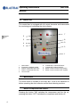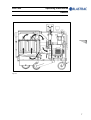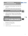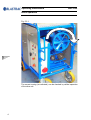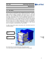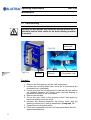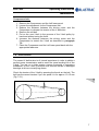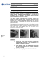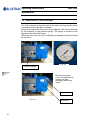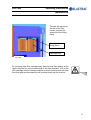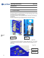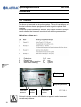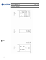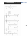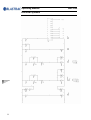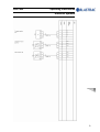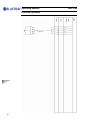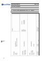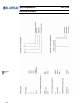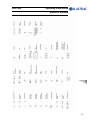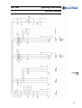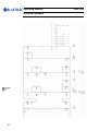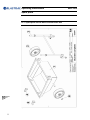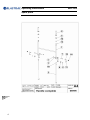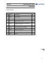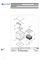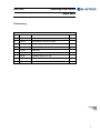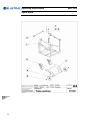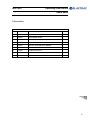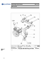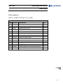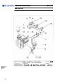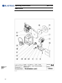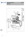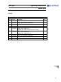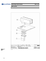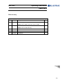
1
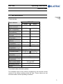
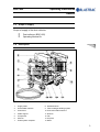
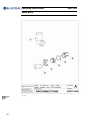
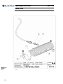
Operating Instructions BDC-655 MAN-BDC-655-EN – REV.A Blastrac BV Utrechthaven 12 3433 PN Nieuwegein THE NETHERLANDS T +31(0)30 - 601 88 66 F +31(0)30 - 601 83 33 E [email protected] I www.blastrac.com Technical data Safety instructions Nieuwegein General Transport Initial operation Operation Maintenance Electrical systems Fault diagnosis Spare parts Design and specifications are subject to change without notice - February 2005 BDC-655 Operating Instructions Technical data Contents Chapter 1 1.1 Rating 1.2 Unit specifications 1.3 Operative range and correct usage 1.4 Stand-by power supply 1.5 Machine type designation 1 Operating Instructions BDC-655 Technical data 1.1 Rating Unit / designation: Blastrac dust collector Machine type BDC-655 Manufacturer Blastrac BV Utrechthaven 12 NL-3433PN Nieuwegein THE NETHERLANDS T +31(0)30 - 601 88 66 F +31(0)30 - 601 83 33 E [email protected] I www.blastrac.com 2 BDC-655 Operating Instructions Technical data 1.2 Unit specifications Technical data Dust collector BDC-655 50 Hz 60 Hz Power consumption Screw conveyor Power consumption 5,5 kW 6,4 kW Fan / compressor Power consumption 5,5 kW 6,4 kW Dust collector Input current Screw conveyor Input current Fan / max.11A max.11A compressor Input current Dust collector 1080 min-1 Rated speed 1100 min-1 Compressor Rated speed Fan 4440 min-1 4530 min-1 IP 54 Enclosure Compressor Enclosure Fan IP 54 400V, 50Hz, 440V, 60Hz, Connected loads 63A CEE Plug 60A UL Plug Ø 130 mm / Ø 150 mm Dust hose connection Dust hose length 20 m Pressure adjusting 6-7 bar Compressor Pressure differential 50-150 mm/WS Filter surface (MAX) 2-6 inch/ WG 15 s Dedusting interval Airflow 1250 m³/h Connected loads (electrical system): The indicated input current values correspond to the nominal current values of the motors working under full load. These values are not achieved under normal operating conditions. 3 Operating Instructions BDC-655 Technical data Dimensions: Dust collector BDC-655 Length Width Height Weight 1730 800 1350 600 mm mm mm kg 1.3 Operative range and correct usage The dust collector BDC-655 is exclusively designed to be used with Blastrac equipment only. It is designed to vacuum dry dust specified to be Class L. (E DIN IEC 61J/94 CD) The Filter material FA 6176 is certified to DIN/EN DUST CLASSIFICATION CLASS L and M. Do not use this equipment on applications where you expect dust that is classified to be harmful. If you feel uncertain ask local authorities for assistance. The manufacturer will not be liable for damage resulting out of from incorrect use. In these cases the user assumes all risks. Dust collector BDC-655: The dust collector BDC-655 is exclusively designed to be used with the blast cleaning machines sizes 1-10, 1-15, 2-20, 350 and 350VH. 4 BDC-655 Operating Instructions Technical data 1.4 Stand-by power supply (Generator) If the dust collector BDC-655 is operated using a generator, this generator must be operated in accordance with the current VDE directives (this applies to the protective earth conductor in particular) in order to ensure that all safety devices are functioning and to eliminate possible damage to electrical components. 1.5 Machine type designation BDC - 6 - 55 Dust Collector number of filters 5.5 kW motor power 5 Operating Instructions Technical data 6 BDC-655 BDC-655 Operating Instructions Safety instructions Contents Chapter 2 2.1 Warnings and symbols 2.2 Organisational measures 2.3 Personnel selection and qualification 2.4 Safety precautions applicable to some operating sequences 2.5 Special work within the scope of use of the dust collector and maintenance activities as well as repairs during operation 2.6 Precautions categories applicable to some particular dangerous 2.7 Oils, greases and other chemical substances 2.8 Safety off position 2.9 Particular dangerous aspects of the equipment Safety regulations Electric 2.10 Regulations 2.11 Pay attention to the order of the following five golden rules 1 Operating Instructions BDC-655 Safety instructions 2.1 Warnings and symbols The following denominations and symbols are used in the Operating Instructions to highlight areas of particular importance: Symbol of operational safety. In these Operating Instructions this symbol will be shown next to all safety precautions that are to be taken in order to ensure prevention to life and injury. Follow these instructions and take special care in these circumstances. In addition to these instructions, the general safety precautions and accident prevention guidelines are also to be followed. Particular details regarding the economical use of the dust collector. Information, instructions and restrictions with regard to possible risks to persons or to extensive material damages. 2 BDC-655 Operating Instructions Safety instructions Warning against dangerous voltages. Indications relating to protective devices in electrical appliances. Indications where consultation with manufacturer of the dust collector is required. the Instructions relating to periodical checks. Reference to important instructions contained in the Operating Instructions. 3 Operating Instructions BDC-655 Safety instructions 2.2 Organisational measures The Operating Instructions are to be kept near the location where the dust collector is located and must be within reach at all times! In addition to the Operating Instructions general and legal regulations regarding accident prevention and environmental protection must be complied with and indicated! Such duties may for example relate to the handling of hazardous substances or to the provision and wearing of personal protection equipment as well as compliance with traffic regulations. The Operating Instructions must be supplemented by instructions including the duty to supervise and report relating to particular working practices, for example work organisation, work procedures and personnel allocation. Personnel entrusted with working with the dust collector must have read the Operating Instructions before starting work, in particular the Safety Instructions chapter. To read these instructions during work is too late. This particularly applies to incidental activities such as setting up the equipment, carrying out maintenance work or training staff to work with the dust collector. From time to time the working practices of the staff are to be checked regarding awareness of safety and hazards. Personnel must tie back long hair and not wear loose clothing or jewellery including rings. There is a risk of injury through getting stuck or being drawn into moving machinery. Use personnel protection equipment if necessary or required by regulations! Take notice of all safety and hazard notices on the dust collector! All safety and hazard notices at or on the dust collector must be kept complete and legible! 4 BDC-655 Operating Instructions Safety instructions If safety-critical changes occur to the dust collector or its working method, the dust collector must be shut down immediately! The cause of the fault must be established immediately! Changes, add-ons or conversions to the dust collector which might impair safety must not be undertaken without the manufacturer's permission! This applies in particular to the fitting and adjustment of safety devices as well as to welding on load-bearing parts. Spare parts must comply with the technical requirements specified by the manufacturer. This is always guaranteed if original spare parts are used. Intervals for recurring checks and inspections specified in these Operating Instructions must be complied with! To perform maintenance work correctly it is imperative to be equipped with the proper tools for the task in question. The location and the operation of fire extinguishers must be made known on each building site! Take note of the facilities for reporting and fighting fires! 2.3 Personnel selections and qualification Fundamental duties: Work on the dust collector may only be undertaken by reliable personnel. Note the statutory minimum age! Only trained personnel may be deployed. Specify clearly the responsibilities of personnel for operation, setting up, servicing and maintenance work! Make sure that only authorised personnel operate or work on the dust collector! Define responsibilities of the equipment operator also regarding to traffic safety regulations and empower him to decline instructions from third parties which are not complying with the safety requirements! 5 Operating Instructions BDC-655 Safety instructions Personnel being trained or made acquainted with the equipment may only be deployed on the dust collector under constant supervision of an experienced person! Work on electrical equipment or operating materials may only be undertaken by a skilled electrician or by trained persons under the guidance and supervision of a skilled electrician as well as in accordance with the electrical engineering regulations. 2.4 Safety precautions sequences applicable to some operating Standard operation Ban any method of working that impairs safety! Some measures have to be taken in order to operate the dust collector in safe and operative conditions! Only operate the dust collector when all safety devices and related safety equipment, e.g. detachable safety devices, emergency stops, sound insulations and suction devices are present and operational! Check the dust collector visually for any damage and defects at least once a day! If alterations or changes appear (inclusive of operating performance), inform immediately the responsible! Shut down immediately the dust collector and secure it, if necessary! In the event of operational malfunctions the dust collector must be shut down immediately and secured! Do not work with the Blastrac dust collector when it rains or on moist surfaces! Do not expose the filter cartridges to moisture! 6 BDC-655 Operating Instructions Safety instructions Faults must be immediately rectified! Carry out the switch on and off operations and pay attention to control display according to the operation manual! Before switching on the dust collector make sure that no-one can be endangered when the dust collector starts up! Do not switch off or remove the exhaust and ventilation devices when the dust collector is running! 2.5 Special work within the scope of use of the dust collector and maintenance activities as well as repairs during operation Adjustment, servicing and inspection work and time limits specified in these Operating Instructions as well as any information on the replacement of parts and equipment must be undertaken and/or complied with! These activities may only be undertaken by qualified personnel. The operator has to be informed about all kind of maintenance works before starting the process! Nominate a responsible person! At all works that are related to normal operation, conversion of tools adjustment of the dust collector and its safety devices as well as before inspection , maintenance and repair all ON and OFF functions have to be carried out according the operation manual and advises for maintenance and repair. Secure the maintenance area, if necessary! If the dust collector is switched off in order to do maintenance , repair or adjustment it has to be secured against unintended restart. Switch OFF and disconnect it from the power supply and secure the main switch with a padlock. 7 Operating Instructions BDC-655 Safety instructions Always dispose the contents of the dust bin of the dust collector before loading it on van or truck. Observe the waste disposal regulations, in uncertain situation ask your next policy level. Use only extension cable for extending the main cable that are sized and marked in accordance with the overall power consumption of the dust collector and of the connected blast cleaning machine and the valid VDE guidelines. All persons in the proximity of the dust collector, when it is working, must wear safety glasses with lateral protection and safety shoes. The operator is obliged to wear close-fitting protective clothing. Do not use any aggressive cleaning materials! Use lint-free cleaning cloths! Always tighten any screw connections that are undone during servicing and maintenance work! If safety devices need to be taken off or dismantled during service and repair, these safety devices must be reinstalled and inspected immediately after completion of the servicing and repair work. Make sure that process materials and replaced parts are disposed of safety and in an environmentally-friendly manner! 2.6 Precautions applicable to some particular dangerous categories Gases, Dust, Steam, Smoke Do not weld, flame cut or perform grinding works on the dust collector without express authorization. It exists danger of fire or explosion! Only work when the dust collector has been switched off and is in the safety off position. Before welding, flame cutting or grinding, remove all dust and combustible materials from the dust collector and from the area and provide adequate ventilation (risk of explosion)! 8 BDC-655 Operating Instructions Safety instructions When working in a confined space, adhere to the appropriate national safety regulations! Switch off the connected dust collector. Place fire extinguishers and fire blankets within easy reach of potential fire hazards. 2.7 Oils, greases and other chemical substances If you use oils, fats and other chemical substances observe the safety regulations in force! 2.8 Safety off position Definition: The dust collector is in a safe condition when it cannot generate any hazard. Putting the equipment in the Safety off position means: ; Put the connected blast cleaning machine in the safety off position according to the instructions. ; Switch off the fan. ; Switch off the compressor. ; Wait for standstill of all drives. ; Pull out main plug. ; Secure main switch with a padlock. 9 Operating Instructions BDC-655 Safety instructions 2.9 Particular dangerous aspects of the equipment Any dust collector, if it is not used according the regulations, may be hazardous for operating, setting-up and service personnel. The operating authority is responsible for compliance with the safety regulations during operation and maintenance of safety devices supplied with the dust collector as well as the provision of appropriate additional safety devices! Dangerous aspects of the equipment are: Fig 2.9.1 1 2 3 10 Wheels Air inlet Air outlet BDC-655 Operating Instructions Safety instructions 2.10 Regulations Work on electrical equipment or operating materials may only be undertaken by a skilled electrician or by trained persons under the guidance and supervision of a skilled electrician as well as in accordance with the electrical engineering regulations. The electrical equipment for the plant must be inspected regularly. Defects such as loose connections or scorched cables must be rectified immediately. Call a skilled electrician or our Customer Services. Be sure that the operators and maintenance personnel are familiar with the following: Lubrication, cleaning and repair works can only be done when the dust collector is in standstill. Make sure that the dust collector can not be set working during the duration of the works. Do not open or remove protective guards while driving gears are running. Once cleaning, lubrication or repair works are finished do not forget to fix again the safety devices. Do not touch any moving parts or stand in their path After cleaning, lubrication and repair works and before starting the dust collector, be certain that any person is in a dangerous area. A second person must be at side in order to manipulate the emergency switch or rather the main switch with overvoltage release if maintenance or repair requires working on live parts. The work area must be blocked off using a red and white safety chain and a danger sign. Use a tool that is insulated against voltages. Only start work once you are familiar with the electrical engineering regulations that apply to your area. 11 Operating Instructions BDC-655 Safety instructions 2.11 Pay attention to the order of the following five golden rules 1. 2. 3. 4. 5. Disconnect all Secure it against unintended restart Check that there is any electric tension Earthing and short-circuiting Put a barrier or cover neighbouring under voltage standing parts The rules 4 and 5 are only prescribed for equipment over 1000 V. Do not be persuaded by third parties to give up the required switching-off while repairing. The above-mentioned meanings of work do not include the troubleshooting, so measurement. Only use voltage seekers that comply with the regulations when troubleshooting. From time to time check voltage seekers to ensure that they are operationally efficient. Only use tools that are in good operating condition. Damaged tools should be immediately repaired or replaced. Use the available personnel protection equipment and safety clothes to protect you when you are working (e.g. safety glasses, safety gloves safety shoes, etc.). 12 BDC-655 Operating Instructions General Contents Chapter 3 3.1 Operating Manual 3.2 Care and maintenance 3.3 Scope of supply 3.4 Description 3.5 Control box 3.6 The suction air system 1 Operating Instructions BDC-655 General 3.1 Operating manual This manual has been written to support the operating personnel on learning the functioning of the dust collector and to guarantee optimum operation and maintenance. Therefore it is important that all persons operating and maintaining the dust collector read this manual carefully and understand it fully. The supplied dust collector has been manufactured for being employed in the user’s country. All descriptions and notes have been formulated in the language of the user’s country or in English in accordance with the statutory regulations, or shown as pictograms. If the customer deploys personnel with little knowledge of the language of the user’s country, appropriate instruction and training must be provided. Before using the dust collector personnel must be familiar with how to operate the machine, with all important components, with the method of working and with its dimensions. Blastrac BV offers a course on the use of the dust collector in order to make the operating and maintenance personnel familiar with all elements of the dust collector. Initial commissioning of the dust collector must be carried out very carefully. The dust collector operator must fully understand the sequence of commissioning of the individual parts and their functioning. 3.2 Care and maintenance Special attendance and regular maintenance of the dust collector are imperative for functioning and safety. 2 BDC-655 Operating Instructions General 3.3 Scope of supply Scope of supply of the dust collector: Dust collector (BDC-655) Operating Manual 2x 3.4 Description Fig. 3.4.1 1 Supply cable 8 Handle dust bin 2 Socket blast machine 9 Filter cartridges & lifting system 3 Control box 10 Connection blast machine 4 Cable support 11 Dust bin 5 Compressor 12 Fan 6 Silencer 13 Air pistol 7 Pulse system complete 14 Motor 3 Operating Instructions BDC-655 General 3.5 Control box The control box is equipped with all control elements and instruments for monitoring and controlling the dust collector. 7 6 5 8 9 4 3 2 1 Fig. 3.5.1 1 2 3 4 5 Main switch Emergency shutdown switch Button “Compressor/Fan OFF“ Button “Compressor/Fan ON“ Hour counter 6 7 8 9 Control lamp “Thermical Failure” Control lamp “Phase incorrect“ Button “Screw conveyor ON“ (option) Button “Screw conveyor OFF“ (option) Main switch The main switch is located on the main box. It has to be switched on before operating the dust collector and the blast cleaning machine. Button Compressor/Fan ON/OFF Pressing the button "ON" switches the compressor and the fan on, pressing the button "OFF" switches the compressor and the fan off. 4 BDC-655 Operating Instructions General Control lamp Thermical failure This lamp shines when the machine is overloaded. Control lamp Phase incorrect This lamp shines when there is a failure with the phases. Emergency shutdown switch Red mushroom-shaped press switch onto a yellow background. Pressing this switch immediately stops the power supply to all units of the machine, shut down switch requires re-setting after it has been used. 3.6 The suction air system The air streaming through the complete system during the application of the blast cleaning machine and the dust collector has the following functions: Cooling of the blast wheels Cooling of the abrasive Transport of the abrasive Transport of dust through the system Separation of dust from the re-useable abrasive Transport of dust to the dust collector 5 Operating Instructions BDC-655 General Motor output: Air throughput: Connected cable length: Dust hose Length: Diameter: 5.5 kW 1250 m³/h 20 m 20 m 130 / 150 mm All connection points must be sealed carefully and the dust hose must be fixed and sealed with duct tape or hose clips ! The filter housing must be sealed properly and all sealings must be in good condition! If dust leaves the dust collector instead of clean air, this is a sign that the filter cartridges are either damaged or not fixed correctly inside the filter chamber. The air streams through the dust collector as follows: The air stream then flows through the approx. 20 m long flexible dust hose taking dust and fine particles with it. The air stream now enters the filter chamber of the dust collector where the dust and the fine particles are separated from the air. The cleaned air is then fed into the environment again. 6 BDC-655 Operating Instructions General Fig. 3.6.1 7 Operating Instructions General 8 BDC-655 BDC-655 Operating Instructions Transport Contents Chapter 4 4.1 General information 4.2 Transport 4.3 Preparations with regard to transport 4.4 Unit specifications 1 Operating Instructions BDC-655 Transport 4.1 General information Before the dust collector is used for the first time, Blastrac BV authorised dealers offer a course to familiarise maintenance and operating personnel with all elements of the dust collector. We are not liable for damage caused by incorrect use of the dust collector by personnel not trained by Blastrac BV. 4.2 Transport When transporting the dust collector proceed in such a manner that damage due to the effects of the use of force or incorrect loading and unloading is avoided. Remove the dust from the dust collector before it is transported. The dust collector may only be lifted by using the suspension eyelets. The weight and dimensions of the dust collector are shown in Chapter 1 "Technical data“. Fig. 4.2.1 2 BDC-655 Operating Instructions Transport 4.3 Preparations with regard to transport The machine is operated in accordance with the instructions given in Chapter 5 ”Initial operation“. The dustcollector is equipped with a cable support. Wrap the supply cable over it in order to avoid damaging during transport. Always activate the brakes on the front wheels in order to prevent running away of the machine Wheel brakes Fig.4.3.1 Remove the dust hose connectors in order not to loose them and to avoid damage to the machine and parts. Dust hose connectors Fig.4.3.2 4.4 Unit specifications Dimensions The main dimensions and unit specifications of the dust collector when assembled are shown in Chapter 1 "Technical data“. 3 Operating Instructions Transport 4 BDC-655 BDC-655 Operating Instructions Initial operation Contents Chapter 5 5.1 Preparations for initial operation 5.2 Initial operation 1 Operating Instructions BDC-655 Initial operation 5.1 Preparations for initial operation Before switching on make sure that all existing protective housings are mounted and that the dust collector is connected correctly. Handle all plugs, cables, hoses and operating devices with care. Avoid any contact with live wires. Works on the electrical system must only be carried out by qualified specialists. Regular inspection is important in order to avoid downtimes of your dust collector. Carry out the following checks before any start-up: ; Check whether all dust collector parts are assembled safely and correctly. ; Check all screws and other fasteners for tight seat ; Check the tightness of the hose connections and the condition of the hose to the filter. ; Check the electrical connections for dirt and foreign body deposits. ; Check the electrical motors for dirt and other contaminants. Before start-up the operating personnel must be familiar with the safety regulations given in this manual. ; 2 Check the main power cable and the dust hose for damage. Replace or repair all damaged parts before starting the machine. BDC-655 Operating Instructions Initial operation ; Connect the blast cleaning machine and the dust collector with the dust hose. Use hose clamps or duct tape at the connections. ; Connect the electric cable of the filter unit with the site supply. Make sure that you use the correct electric supply (Chapter 1.2). Press the test button to check the function of the residual current operated device! ; Check that the dust container of the dust collector is empty. ; Check the presence of moisture in the air pulse system by activating the air pistol; releasing air pressure will enable the water separator to drain . This allows a better functioning of the air pulse system. 5.2 Initial operation All persons in the proximity of the dust collector must wear ear protectors, safety glasses with lateral protection as well as safety shoes. The operator is obliged to wear close-fitting protective clothing. The start of the dust collector is effected in the following sequence: 1 Switching on of the dust collector Main switch of the dust collector "ON" Compressor/Fan "ON" Check the turning direction of the filter and compressor motor. 3 Operating Instructions BDC-655 Initial operation Fig. 5.2.1 The correct turning (as indicated ) can be checked by visible inspection of the drive unit. 4 BDC-655 Operating Instructions Initial operation How to correct the turning direction of the driving motors Switch off the driving gears. Switch off the main switch. Open the control box of the dust collector. Set the inverter switch to the opposite position Inverter switch Fig.5.2.2 Close the control box Check again the turning direction of the driving gears. The initial operations take place in accordance with the chapter "Initial operation" of the operating manual of the blast cleaning machine. The dust container of the dust collector must be emptied regularly. 5 Operating Instructions Initial operation 6 BDC-655 BDC-655 Operating Instructions Operation Contents Chapter 6 6.1 Operation 6.2 Connecting the dusthose 6.3 Emptying the dustbin 6.4 Air pulse system / water drainage 6.5 Switching-off the dust collector 6.6 Trouble shooting 6.7 Safety shutdown 6.8 Restarting after a fault 6.9 Proceedings- prior and after a stationary period 1 Operating Instructions BDC-655 Operation 6.1 Operation Normal start-up and operation of the dust collector BDC-655 is no different from the procedure described in Chapter 5 “Initial operation”. Make sure that no vehicles, such as forklift trucks and other equipment run over the electric cable and the dust hose. 6.2 Connecting the dusthose To connect a Blastrac machine to the dustcollector, a hose with internal diameter of 130 mm. or 150 mm. can be used. Valve 150-130 mm. This valve is suitable for the 150 mm. hose, as well as the 130 mm. hose. Hose 150 Connect hose 150 and fix with ducttape or hoseclamp. Fig.6.2.1 2 BDC-655 Operating Instructions Operation Hose 130 Slip hose 130 and fix with ducttape. Fig.6.2.2 When inserting the hose 130 mm. in the valve, assure the edge does not exceed the limit pins . Assure the valve can be adjusted freely. pin Fig.6.2.3 3 Operating Instructions BDC-655 Operation 6.3 Emptying the dustbin The level of the dustbin must be regularly checked. The periods are dependent on the surface to be cleaned. Locking pin Handles Fig.6.3.1 Rotate the handles in shown direction to release the locking pins. Push the handle down and lock it in lower position to enable separation of the dustbin from the filter house. 4 BDC-655 Operating Instructions Operation Dustbin positioning system Fig.6.3.2 After emptying the dustbin, carry out the actions in opposite sequence. Ensure that the dustbin is at a correct way repositioned. If not, there can occur a major leakage in the dust collector system. Safety precaution: Pay attention to the increased weight of the dustbin when you release the locking device. Loosen the handle with caution! Assure frequently emptying the dustbin. When the level of the dustbin exceeds the limit of its contents , the filters may get clogged up excessively , which then can lead to cracks. Dust will then access the machine and cause damage to parts and systems of the filter unit. Dust exceeding the level of the dustbin contents may also lead to a heated up filter unit, which can cause defects to parts and systems of the filter unit. An indication of dust exceeding the limits of the dustbin contents, can also be recognized by an high indication of the pressure gauge. The gauge is located on the opposite side of the filter house (Fig. 6.3.3). When the value of 8 cm H2O (=0.008 bar) or higher is indicated, the dustbin should be checked. Frequency of checking the dustbin may vary upon the sort of utilisation of the dustcollector. 5 Operating Instructions BDC-655 Operation Fig.6.3.3 Pressure gauge 6.4 Air pulse system / water drainage The air pulse system assures that the cartridge filters do not get clogged. An airpulse generated by the compressor blow out the filters from within. Moisture, which is present in the air, is separated by the waterseparator, showed in fig.6.4.1. This is an automatic device. Except when drained manually, by pressing the outer ring (fig. 6.4.2), it can only function when once in a while the air pressure is relieved from the pulse system. Outlet ring Level indicator marking Fig. 6.4.1 6 Fig. 6.4.2 BDC-655 Operating Instructions Operation Do this by activating the airpistol, located below on the machine (shown in fig. 6.4.3). Do this at least when emptying the dustbin , the frequency however may vary upon atmospheric humidity. Fig.6.4.3 Air pistol Assure air pressure relief in order to maintain correct functioning of the water separator. Moisture in the filters can cause clogging up the cartridge filters excessively , which then can lead to cracks. Dust will then access the machine and cause damage to parts of the filter unit. 6.5 Switching-off the dust collector After finishing the blast cleaning process, the dust collector must run several minutes to dedust the filter cartridges. After several minutes press the push button "Compressor/Fan OFF". Relief air pressure of the pulse system by activating the airpisol. Set the main switch of the filter unit to "OFF". Make sure that all turning dust collector parts have come to standstill before any inspection or maintenance works are started. When the Blastrac dust collector is put out of operation for a longer period of time, pull out the mains plug and cover the dust collector with a plastic foil. 7 Operating Instructions BDC-655 Operation 6.6 Trouble shooting Irrespective of the following information, the local safety regulations are valid in any case for the operation of the dust collector. First put the dust collector to its Safety off position. Afterwards start searching for the fault. 6.7 Safety shutdown The dust collector has to be into its “Safety off position” before starting repair works. See Chapter 2.5 “Safety instructions”. 6.8 Restarting after a fault See Chapter 5 “Initial operation“. All persons in the proximity of the dust collector must wear ear protectors, safety glasses with lateral protection as well as safety shoes. The operator is obliged to wear close-fitting protective clothing. 8 BDC-655 Operating Instructions Operation 6.9 Proceedings- prior and after a stationary period Stand still of the machine for a maximum of 3 months. Before a long standstill period ; Switch off the dust collector. (See chapter 6.5) ; Protect the electric motors from moisture, heat, dust and shocks. ; Clean the machine and cover it with a plastic foil. ; Preserve bright parts of the dust collector with Tectyl 506, for example, or a similar preservative. After a long standstill period See Chapter 5 “Initial operation 9 Operating Instructions Operation 10 BDC-655 BDC-655 Operating Instructions Maintenance Contents Chapter 7 7.1 Recommendations 7.2 Maintenance and inspection list 7.3 Repairing 7.4 V-belt 7.5 Mounting V-belt 7.6 V-belt tension 7.7 Taper-Adaptor sleeve 7.8 Replacement of filter cartridges 7.9 Air pulse system 7.10 Waterseparator 7.11 Compressor 7.12 Timer unit 1 Operating Instructions BDC-655 Maintenance 7.1 Recommendations Pay attention to Chapter 2 "Safety information" during maintenance and repair works. Failures due to inadequate or incorrect maintenance may generate very high repair costs and long standstill periods of the dust collector. Regular maintenance therefore is imperative. Operational safety and service life of the dust collector depend, among other things, on proper maintenance. The following table shows recommendations about time, inspection and maintenance for the normal use of the dust collector. The time indications are based on uninterrupted operation. When the indicated number of working hours is not achieved during the corresponding period, the period can be extended. However a full overhaul must be carried out at least once a year. Due to different working conditions it can’t be foreseen how frequently inspections for wear check’s, inspection, maintenance and repair works ought to be carried out. Prepare a suitable inspection schedule considering your own working conditions and experience. Our specialists will be happy to assist you with more advice. Prior to any repair works on the dust collector and its drives, secure the dust collector against unintentional switching-on. Put the dust collector to its safety off position. Also make sure there is no air pressure on the pulse system. Follow additional operating and maintenance of OEM if included during your service and maintenance work. 2 BDC-655 Operating Instructions Maintenance 7.2 Maintenance and inspection list Operating hours/ time period Inspection points, maintenance instructions 12 h after repairing Check all accessible screw connections for tight seat. Daily and prior to starting work Check all safety devices working adequate. Check the function of the residual current operated device. Check the hose connections for tightness and fixed seat. Check the hose to the filter for damages. Make sure that the dust bin of the filter is emptied Check the electric connections for sediments of dirt or foreign bodies. Check the electric motors for dirt and other contaminants. Annually Full overhaul and cleaning of the complete dust collector. After 50 working hours Change compressor oil. After 300 working hours, using mineral oil Change compressor oil. After 900 working hours, using synthetic oil Change compressor oil. 7.3 Repairing As already mentioned in Chapter 5 “Initial operation” we recommend executing the first repair works on the dust collector having support of Blastrac BV personnel. Doing this together, your maintenance personnel gets the opportunity to be trained intensely. 3 Operating Instructions BDC-655 Maintenance We will describe only regular maintenance works that could occur within the bounds of regular maintenance or work that is required to replace wear parts. If you replace parts yourself for specific reason, the following instructions and work sequence have to be observed. You should also stock all spare or wear parts that cannot be supplied quickly. As a rule, production standstill periods are more expensive than the cost for the corresponding spare part. Screws that have been removed must be replaced with those of the same quality (strength, material) and design. Prior to any repair works on the dust collector and its drives, secure the dust collector against unintentional switching-on. Pull out the mains plug in order to do this. Also make sure there is no air pressure on the pulse system. 4 BDC-655 Operating Instructions Maintenance 7.4 The V-belts The V-belt drive is designed for the installed driving power. To force a higher output through an excessive high tension of the V-belt will break the belt, damage bearings and cause losses of the total efficiency. Too low belt tension will cause slipping with the result of a very high temperature of the V-belt a premature destruction of it. Temperatures over 70° for a longer period will decrease the working life and the efficiency of the V-belt. The grooves of the V-belt pulleys must be free of rust, fat and dirt and must not show any damages. The use of belt wax or similar substances in order to increase the friction coefficient is not necessary and it damages the V-belt. Soiling due to oil, grease or chemicals have to be avoided. In order to get perfect power transmission the V-belt drive has to be checked regularly. Compressor panel Left panel lower Fig.7.4.1 The V-belt drive is located behind the Compressor panel. The V-belt tension device is located behind the Left lower panel. 5 Operating Instructions BDC-655 Maintenance 7.5 V-belt mounting Remove the belt guards only when the driving motors are in standstill and the main switch of the blast cleaning machine is secured. Fig.7.5.2 Fig.7.5.1 V-belts Adjustment Fan belt Mounting plate bolts Adjustment Compressor belt Fan belt : 1. Remove the Compressor and the Left lower panel. 2. Loosen the mounting plate bolts, there are 4 bolts which are reachable from underneath. 3. Loosen the bolts for the adjustment of the fan belt and reduce the distance between the driving motor and the bearing to release the tension of the V-belt drive. 4. Remove the old belt. 5. Put on the new V-belt in the grooves of the V-belt pulley by hand and without using the force. 6. Increase the distance between the driving motor and the bearing to stretch the V-belt as described in paragraph 7.6. 7. Fasten the mounting plate bolts. 8. Place the Compressor and the Left lower panel back with the appropriate fasteners. 6 BDC-655 Operating Instructions Maintenance Compressor belt : 1. Remove the Compressor and the Left lower panel 2. Loosen the adjustment for the Compressor belt . 3. Reduce the distance between the driving motor and the Compressor to release the tension of the V-belt drive. 4. Remove the old belt. 5. Put on the new V-belt in the grooves of the V-belt pulley by hand and without using the force. 6. Increase the distance between the driving motor and the Compressor to stretch the V-belt as described in paragraph 7.6. 7. Place the Compressor and the Left lower panel back with the appropriate fasteners. 7.6 V-belt tension The correct V-belt tension is of utmost importance in order to obtain a perfect power transmission and to reach the usual working life of the V-belt. Too low or to high tension causes frequently a premature breakdown of the V-belt. Excessive belt tension results in damaged bearings at drives or scarifying drums. Check the tension of the V-belt by pressing the thumb on the belt. The belt has the correct tension if you can press it in for approx. 10-15 mm (Fig. 7.6.1). Fig. 7.6.1 7 Operating Instructions BDC-655 Maintenance 7.7 Taper-Adapter sleeve Hubs will be fixed like a shrunk-on fit on shafts with the help of taper adapter sleeves. To assembly and disassembly it you need only a screw driver DIN 911 (Allan key). The same set screw or rather the same screws serve to loose and to stretch. The taper – adapter sleeve are inside cylindrical, outside cone shaped and slotted along the length. The smaller sleeves have in the big face 2 and 3 cylindrical blind holes parallel to the axis. One half lies on the material of the sleeves and the other half lies in the hub and have threads. Set screws or rather screws will be screwed in with a Allan key to the stop in the face bores. When the screws are powerful tightened, the hub will be drawn on the shaped sleeve and the sleeve will be pressed with force on the shaft. Fig. 7.7.1 Fig. 7.7.2 Fig. 7.7.3 Dismount: 1. Dismount the screws of the belt-pulleys. Lubricate the threads and the coned point of one screw and turn it in the bore, as described in the figure. 2. Screw down the screws until the sleeve sits loose in the belt pulley and consequently the structural components are loose on the shaft. 3. Remove the belt-pulley and the sleeve from the shaft. 8 BDC-655 Operating Instructions Maintenance Mount: 1. Make sure that all surfaces they lie superpose are dirt and oil free. Set the sleeve in the belt pulley. 2. Lubricate a little the screws and insert it in the designated tap hole. 3. Clean the shaft and push the pulley with the sleeve, as a unit, on the shaft and set the structural components. Make sure that the sleeve will be first tightened on the shaft and then the belt pulley lifted up by the sleeve. 4. Use a Allan key to tighten the screws progressively and alternately. 5. Hit with a hammer the face of the sleeve to make sure that it is seated axial in the pulley. (Use a drift to avoid damages.) 6. Now tighten the screws. Hammer and tighten alternately until the screws are tight. 9 Operating Instructions BDC-655 Maintenance 7.8 Replacement of filter cartridges The Dust collector is provided with a air pulse cleaning system which increases the life of the filter cartridges. However periodical the filters have to be replaced. This can be checked by the indication of the pressure gauge. The gauge is located on the opposite side of the filter house. When the value of 8 cm H2O (=0.008 bar) is indicated, the filters should be replaced. Pressure gauge Fig.7.8.1 Remove the upper cover and side door to access the filter cartridges and lifting frame. Upper cover Fig.7.8.2 10 Side door BDC-655 Operating Instructions Maintenance Through the access at the top of the filter house, unscrew the wingnuts of the lifting frame. Cartridge filter lifting frame Cartridge filter Fig.7.8.3 By mounting new filter cartridges pay attention that their gasket at the upper side lies firm at the sheet steel of the filter chamber. A tilt of the filter cartridge result in leakage and then suction contaminants will enter the clean part and consequently will be blown back into the outer air. 11 Operating Instructions BDC-655 Maintenance 7.9 Air pulse system The Dust collector is provided with a air pulse cleaning system which increases the life of the filter cartridges. The system works by use of pressurized air, built up by a belt driven compressor The air is leaded through a waterseparator to the pulse system. Compressor Fig.7.9.1 Water separator Fig.7.9.2 The conditioned air then passes a control valve (see fig. 7.9.4), which regulates the systems pressure , and then builds up pressure in the pulse tank. Fig.7.9.3 Safety valve Pulse tank 12 BDC-655 Operating Instructions Maintenance Control valve Fig.7.9.4 Pressure gauge Fig.7.9.5 The pressure in the pulse system is indicated on the pressure gauge. It is mounted in the Filter house next to the vacuum gauge. Normally the pressure in the system lies between 6 up to 7 bar. This is regulated by the control valve. The safety valve mounted on the pulse tank is activated at approximately 10 bar. If the pressure of 7 bar is not reached, it is possible that either the filter of the water separator or the air filter of the compressor is dirty. For maintenance instructions on the waterseparator see paragraph 7.10. For maintenance instructions on the compressor see paragraph 7.11 If inspection on the waterseparator or compressor shows no dirty filter, it is possible that either there is a leakage in the air tubing, or 13 Operating Instructions BDC-655 Maintenance the control valve is defect. In that case replace the defective parts or have it checked by Blastrac. When there is pressure but the pulse system does not function, there might be a problem in the electrical system which controls the pulsing system. Check the wiring and the timer-unit settings. For timer-unit settings see paragraph 7.12 . Timer unit Fig.7.9.6 7.10 Water Separator Periodically check the level indicator of the waterseparator. If there is condensate level approximately 10 mm below the level indicator marking (see figure 7.10.1 ) then either press in or turn the outlet ring as shown on figure 7.10.3 . Outlet ring Fig. 7.10.2 Level indicator marking Fig. 7.10.1 In case of less air flow as mentioned in paragraph 7.9, replace the filter of the waterseparator as following: 14 BDC-655 Operating Instructions Maintenance Push unlocking slide down and turn filter bowl in anti-clockwise direction. Then pull filter bowl away from the separator. Fig. 7.10.3 15 Operating Instructions BDC-655 Maintenance Turn the filter screw loose and replace the dirty filter by a new one as shown on figure 7.10.4 . Hold the new filter element only at the lower end . Fig. 7.10.4 Fig. 7.10.5 Fig. 7.10.6 Fasten the filter screw and place the filter bowl back . Make sure the locking pin points towards the large recess (see figure 7.10.5 ). When fastening the filter bowl, make sure you hear a clear snap. 16 BDC-655 Operating Instructions Maintenance 7.11 Compressor The oil level and air filter of the compressor should periodically be inspected acc. to the in table of chapter 7.2 given values. Replacement or cleaning of the air filter is depending on the environment in which the Dust collector is operating. Oil level indicator Fig.7.11.1 Air filter Fig.7.11.2 The height of the oil level oil level must lay on approximately half of the oil level indicator , about 0,25 liter. Use only oil especially mend for compressors, according specification C.T. 68 ( ISO 68 – viscosity ) . Prior to draining-off , the compressor unit should have operating temperature. 17 Operating Instructions BDC-655 Maintenance 7.12 Timer-unit The timer unit controls the air pulse system. This unit is at delivery of the dust collector already programmed with regard to optimal filter cleaning. If however doubts arise about settings, they can be checked. Always check whether the timer unit is switched on with the power button. Indication on timer unit : Standard settings : 1 2 3 4 Pulse time Pause time Number valve selection Shut down cleaning 0.25 15 3 50 sec sec valves cycles Display Adjusting buttons Release screws Power button Selection button Fig.7.12.1 Advised is to take contact with Blastrac support in order to prevent operational problems. 18 BDC-655 Operating Instructions Electrical systems Contents Chapter 8 8.1 Electric circuit diagrams BDC-655 – EC - version 8.2 Electric circuit diagrams BDC-655 – UL - version 1 Operating Manual Electrical systems 8.1 Electric circuit diagrams BDC-655 – EC - version 2 BDC-655 BDC-655 Operating Instructions Electrical systems 3 Operating Manual Electrical systems 4 BDC-655 BDC-655 Operating Instructions Electrical systems 5 Operating Manual Electrical systems 6 BDC-655 BDC-655 Operating Instructions Electrical systems 7 Operating Manual Electrical systems 8 BDC-655 BDC-655 Operating Instructions Electrical systems 9 Operating Manual Electrical systems 10 BDC-655 BDC-655 Operating Instructions Electrical systems 11 Operating Manual Electrical systems 8.2 Electric circuit diagrams BDC-655 – UL - version 12 BDC-655 BDC-655 Operating Instructions Electrical systems 13 Operating Manual Electrical systems 14 BDC-655 BDC-655 Operating Instructions Electrical systems 15 Operating Manual Electrical systems 16 BDC-655 BDC-655 Operating Instructions Electrical systems 17 Operating Manual Electrical systems 18 BDC-655 BDC-655 Operating Instructions Electrical systems 19 Operating Manual Electrical systems 20 BDC-655 BDC-655 Operating Instructions Fault diagnosis Contents Chapter 9 9.1 Fault diagnosis - dust collector 9.2 Fault diagnosis electrical system 1 Operating Instructions BDC-655 Fault diagnosis 9.1 Fault diagnosis - dust collector Prior to any repair works on the equipment or its drives the equipment must be secured against unintentional switchingon. Put the machine to its Safety off position. Fault Possible cause Remedy Unusual noises. To little clearance or wrong adjustment of the rotating parts. Check the adjustment of the rotating parts. Check screws and all parts for tight seat. To low Check the whole pressure or pneumatic system for any pressure. leaks. Stop up the leaks or replace the damaged components. Check settings of control valve or replace it when defect. Replace filter element of waterseparator when dirty . Any suction power. Bad or any dedusting. Check the tension of the V-belt compressor. Stretch the V-belt Dirty filter cartridge. Clean or replace the filter cartridge. Check the tension of the V-belt fan. Stretch the V-belt. Foreign airs through leaks in the hopper or in the housing cover seal. Replace the seal. To low air pressure in pulse air system. See over. Dedusting timer card or solenoid valve defective. Replace defective parts. 2 BDC-655 Operating Instructions Fault diagnosis Loud running noises. It is missing grease in fan bearing. Lubricate the fan bearing. Silencer assembly defective. Replace it. Oil level of compressor to low Fill compressor oil level up. 3 Operating Instructions BDC-655 Fault diagnosis 9.2 Fault diagnosis electrical-system Prior to any repair works on the equipment or its drives the equipment must be secured against unintentional switchingon. Put the machine to its Safety off position.. Fault Possible cause Remedy Fan/ compressor does not switch on. Motor protections switch triggered. Check the mains power supply and next switch on again. Check voltage and existence of 3 fases. Control lamp Motor protections switch for motor triggered. protection switch flashes. Overload current because of defective equipment (Motor, etc). Switch on again the motor protections. Have the unit checked by an electrician. Control Dust collector safety fuse Have the unit checked by switches off or residual current an electrician. while working. operated device has triggered. Connection cable is defective. Replace the cable. Main switch of the dust Main switch "Off", with collector switches off due fault, have the unit to overload. checked by an electrician. Note: If the motor protection switches off the blast wheel motor, triggered by overload, they can be switched on again after a short cooling down period. 4 BDC-655 Operating Instructions Spare parts Contents Chapter 10 10.1 Spare parts 1 Operating Instructions Spare parts 10.1 Spare parts list for dust collector BDC-655 Fig.10.1 2 BDC-655 BDC-655 Operating Instructions Spare parts Dustbin complete E03011 – DUSTBIN COMPLETE ITEM PART-NO. DESCRIPTION CTY. 1 E03012 DUST BIN 1 2 B20969 WHEEL 2 3 E00890 HANDLE COMPLETE 1 4 E03013 DUST BIN HOLDER LEFT 1 5 E03014 DUST BIN HOLDER RIGHT 1 6 E03747 ADJUSTING RING WITH SCREW 2 3 Operating Instructions Spare parts Fig.10.2 4 BDC-655 BDC-655 Operating Instructions Spare parts Handle complete E00890 – HANDLE COMPLETE ITEM PART-NO. DESCRIPTION QTY. 1 E00891 HANDLE 1 2 E00895 INNER HANDLE 2 3 M10 WASHER 2 4 M10 NUT PLASTIC INSERT NUT 2 5 CIRCLIP DIN 471 - 15 X 1 2 6 E01304 BALL BEARING 2 7 E03113 HEXAGON SOCKET HEAD SHOULDERS SCREW M10 -12X50 2 8 453290 HANDLE GRIP 2 9 E03747 ADJUSTING RING WITH SCREW 2 10 E03081 O – RING Ø25 X 4 4 11 E00896 ARM FOR LOCKING PIN 2 12 E00897 LOCKING PIN 2 SHIM 26 X 37 X 1 2 SPRING 2 13 14 E03072 5 Operating Instructions Spare parts Fig.10.3 6 BDC-655 BDC-655 Operating Instructions Spare parts Filterhousing E03108 - FILTERHOUSING ITEM PART-NO. DESCRIPTION QTY. 1 E03015 FILTER BODY 1 2 E03016 CARTRIDGE LIFTER SYSTEM 1 3 E01309 SEAL 3M 4 E10218 CARTRIDGE 6 5 E14028 VENTURI 6 6 E03020 COVER PLATE 1 7 E00881 RUBBER IMPACT PLATE 1 8 E03031 PULSE SYSTEM COMPLETE 1 9 E03018 SIDE DOOR 1 7 Operating Instructions Spare parts Fig.10.4 8 BDC-655 BDC-655 Operating Instructions Spare parts Tube section E03068 – TUBE SECTION ITEM PART-NO. DESCRIPTION QTY. 1 E03063 TUBE FRAME 1 2 E03067 STIFFENER BEAM 1 3 E10407 FRONT AXIS DEVICE UNIT 1 4 E10202 WHEEL 2 5 E10207 SWIVEL CASTOR WITH BRAKE 2 6 E03748 ADJUSTING RING WITH SCREW 2 7 E03082 CABLE SUPPORT 2 8 E03119 SPRING 2 M10X60 HEX.SOCKET HEAD CAP 2 9 9 Operating Instructions Spare parts Fig.10.5 10 BDC-655 BDC-655 Operating Instructions Spare parts Pulse system (1) Serial nr. 2148B, 2151B up to / incl. 2155B E03104 – PULSE AIR INSTALLATION ITEM PART-NO. DESCRIPTION QTY. 1 001244 AIR FILTER 1 1A 656384 FILTER ELEMENT ONLY 1 2 B21750 NON RETURN VALVE 1 3 E01300 AIR VALVE 3 4 E01303 SAFETY VALVE 1 5 E03033 PULSE TUBE 3 6 E03032 TANK PULSE SYSTEM 1 7 2381-365 FILTER VACUÜM GAUGE 2 8 491837 VACUÜM GAUGE 1 9 E10349 MANOMETER 1 10 490691 CONTROL VALVE COMPRESSOR 1 11 E00635 WATER SEPARATOR 1 E00635/1 FILTER ELEMENT FOR WATER SEPARATOR 1 E03075 MOUNT PLATE 1 11A 12 11 Operating Instructions Spare parts Fig.10.6 12 BDC-655 BDC-655 Operating Instructions Spare parts Pulse system (2) Serial nr. 2156B and up E03104 – PULSE AIR INSTALLATION ITEM PART-NO. DESCRIPTION QTY. 1 E03815 AIR FILTER 1 2 B21750 NON RETURN VALVE 1 3 E01300 AIR VALVE 3 4 E01303 SAFETY VALVE 1 5 E03033 PULSE TUBE 3 6 E03032 TANK PULSE SYSTEM 1 7 2381-365 FILTER VACUÜM GAUGE 2 8 491837 VACUÜM GAUGE 1 9 E10349 MANOMETER 1 10 490691 CONTROL VALVE COMPRESSOR 1 11 E00635 WATER SEPARATOR 1 E00635/1 FILTER ELEMENT FOR WATER SEPARATOR 1 12 E03075 MOUNT PLATE 1 13 E03816 FILTER ADAPTOR 1 14 E01563 AIR SUCTION HOSE 1 11A 13 Operating Instructions Spare parts Fig. 10.7 14 BDC-655 BDC-655 Operating Instructions Spare parts Ventilation unit E03064 – VENTILATION UNIT ITEM PART-NO. 50 HZ DESCRIPTION QTY. 60 HZ 1 E03069 HINGE PLATE ASSY 1 2 E00999 BEARING UNIT COMPLETE 1 3 E10213 MOTOR 5.5 KW 1 4 E03071 MOTOR HOUSING 1 M16 X 140 EYE BOLT 1 5 6 490693 COMPRESSOR 1 7 E03142 FAN HOUSING 1 8 E03150 FANCOVER 1 9 493399 FAN IMPELLER 1 10 E10422 SHOCK ABSORBER 4 11 E10418 SHOCK ABSORBER 4 12 E03077 PROTECTION PLATE 1 BELT PULLEY 1 13 E10413 E00275 14 E10415 TAPER LOCK BUSH 1 15 B22078 TAPER LOCK BUSH 1 16 DG14 BELT PULLEY 1 17 E03103 V-BELT 2 18 E03102 V-BELT 1 19 E03195 RING FAN 1 15 Operating Instructions Spare parts Fig. 10.8 16 BDC-655 BDC-655 Operating Instructions Spare parts Panels 655DC-0000 - PANELS Item Part-No. Description Qty.. 1 E03091 PANEL COMPRESSOR COMPLETE 1 2 E03093 PANEL BOX COVER COMPLETE 1 3 E03094 PANEL RIGHT COMPLETE 1 3A E03106 GROMMET 1 4 E03823 PANEL TOP COMPLETE - 1 (SERIAL NR. 2148B, 2151B TO / INCL. 2155B 4 E03853 PANEL TOP COMPLETE – 1 (SERIAL NR. 2156B AND UP) 5 E03098 PANEL LEFT UPPER COMPLETE 1 6 E03097 PANEL LEFT LOWER COMPLETE 1 7 E03092 COVER ANGLE 1 17 Operating Instructions Spare parts Fig. 10.9 18 BDC-655 BDC-655 Operating Instructions Spare parts Silencer assy 655DC-0000 – SILENCER ASSY Item 1 Part-No. E03791 Description ADAPTOR (SHIFTING) - Qty.. 1 (SERIAL NR. 2148B, 2151B TO / INCL. 2156B 1 E03801 ADAPTOR (STRAIGHT) – 1 (SERIAL NR. 2157B AND UP) 2 E03795 SEAL PLATE RUBBER 1 3 E03794 PRESS PLATE 1 4 492425 SILENCER 1 19 Operating Instructions Spare parts Fig. 10,10 20 BDC-655 BDC-655 Operating Instructions Spare parts Airconnections Serial nr. up to incl. 2162B 655DC-000 – AIRCONNECTIONS ITEM PART-NO. DESCRIPTION QTY. 1 490706 CONNECTION HOSE 200 L=600 1 2 E03128 CONNECTION HOSE 150 L=250 1 3 E03084 CONNECTION SUPPORT 1 4 E03083 CONNECTION PART 1 (SERIAL NR. UP TO INCL. 2162B ) 5 E03105 ADAPTER SEAL 1 (SERIAL NR. UP TO INCL. 2162B ) 6 E03096 – REV.E VALVE COMPLETE Ø150 - Ø130 1 (SERIAL NR. UP TO INCL. 2162B ) 21 Operating Instructions Spare parts Fig. 10,11 22 BDC-655 BDC-655 Operating Instructions Spare parts Airconnections 2 Serial nr. 2163B and up 655DC-000 – AIRCONNECTIONS 2 ITEM PART-NO. DESCRIPTION QTY. 1 490706 CONNECTION HOSE 200 L=600 1 2 E03128 CONNECTION HOSE 150 L=250 1 3 E03084 CONNECTION SUPPORT 1 4 E03798 CONNECTION PART 1 (SERIAL NR. 2163B AND UP ) 5 E03874 ADAPTER SEAL 1 (SERIAL NR. 2163B AND UP ) 6 E03797 VALVE COMPLETE Ø150 - Ø130 (SERIAL NR. 2163B AND UP ) 1 23 Operating Instructions Spare parts Fig.10. 12 24 BDC-655 BDC-655 Operating Instructions Spare parts Control system E03110 – CONTROL UNIT COMPLETE ITEM 1 PART-NO. DESCRIPTION 50 Hz 60 Hz E10346 E03171 QTY.. CONTROL PANEL 1 1A E01301 TIMERUNIT 1 2 E03079 INSTR.PANEL SUPPORT 1 3 E03109 PULSE CABLE COMPLETE 1 NEOPRENE CABLE (L=15 MTR.) 1 PLUG 1 SUPPORT AIRFILTER 1 4 999-3346/ 15 E00608 5 500-3195 INCLUDED I N E00608 6 E03126 25 Operating Instructions Spare parts Fig.10.13 26 BDC-655 BDC-655 Operating Instructions Spare parts Air pistol E03170 – AIRPISTOL ASSY ITEM PART-NO. DESCRIPTION QTY. 1 E03160 HOSE CLIP 1 2 DA—9290.1 AIRPISTOL 1 3 DA—9290.2 AIRHOSE 6 MM. L 5 MTR. 1 4 E03168 MINI-QUICKCOUPLING 1 5 E03169 MINI-NIPPEL 1 27 Operating Instructions Spare parts 28 BDC-655