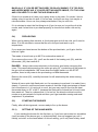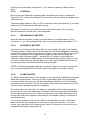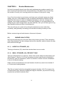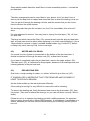
1
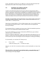
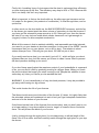
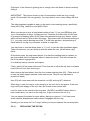
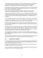
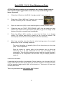
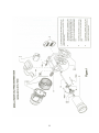
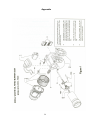
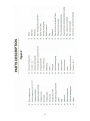
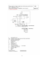
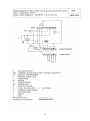
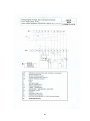
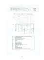
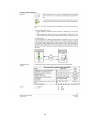
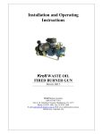
Installation and Operating
Instructions*
Kroll WASTE OIL BURNER GUN
MODELS BR10, BR15, AND BR20
.
Kroll Heaters Australia
ABN 67108717451
Factory 6, 4 Kirkham Road, Dandenong, Vic, 3175
Phone: 03 9791 3082 Fax: 03 9791 3048
E: [email protected] W: www.kroll-heaters.com.au
FREECALL 1800 805 243
* ENERGY OPTION VERSION
1
INDEX
Pg
Introduction
2
Chapter 1
Principle of Waste Oil Burning
3
Chapter 2
What is “Waste Oil”?
4
Chapter 3
Mounting the Burner Gun
5
Chapter 4
Oil Feed
6
4.1)
4.2)
4.3)
4.4)
4.5)
4.6)
4.7)
4.8)
Chapter 5
Main Storage Tanks
Day Tank
Pipeline from Main Tank to Day Tank
Gravity Feed System
Pump Transfer System
Oil Feed from Day Tank to Burner Gun
Filtration
De-Gassing
Starting and Running the Burner Gun
5.1)
5.2)
5.3)
5.4)
5.5)
Chapter 6
Sequence Of Functions (How The Burner Works)
Choosing The Correct Setting For Your Heater Or Boiler
Secondary Air
Pre-Heating
Starting The Burner
Routine Maintenance
6.1)
6.2)
6.3)
6.4)
6.5)
6.6)
6.7)
6.8)
6.9)
12
20
Burner Gun Filters
Water And Oil Drain
Pre-Heating Rod
Nozzle Pipe Assembly
Photo-Electric Cell (6)
Hydraulic Coupling, (64)
Electrovalve, (33)
Cover For Worm Gear (41)
End Of Heating Season
Chapter 7
Faults, Possible Causes and Remedies
27
Appendix
Short Maintenance Guide, Exploded Parts View & Circuits
30
2
Introduction
Thank you for choosing a Kroll waste oil fired burner.
This manual will explain how to install, operate and maintain your burner.
Kroll burners can be fitted to air furnaces or heaters which push out warm air, or to
boilers, to produce hot water. It’s important that you also read the separate manual
about that apparatus in conjunction with this burner manual.
When you burn waste oil in a Kroll burner, provided you have it adjusted correctly,
and attached it to a compatible heater or boiler, it will run cleanly and reliably.
BUT, in exchange for being able to run on this free or inexpensive fuel, you have to
put up with inconvenience of some extra maintenance compared to using gas,
heating oil or electricity.
If you are not prepared to carry out this extra maintenance, then, to be blunt, you
have bought the wrong heater!
Generally speaking, the savings on running costs are so great that this effort and
inconvenience on your part are well worthwhile.
We believe that in order to look after your burner, you need to have a good
understanding of how it works.
So please take the trouble to read through this manual.
We cannot look after your Kroll for you. We can only make it as easy as possible for
you to do it yourself by giving you the information you need.
Please be patient. Read all the way through this manual, and “digest” it, before
attempting to start your burner.
3
CHAPTER 1:
Principle of Waste Oil Burning
Waste oil has a high flash point, compared to conventional heating oil. This means it
does not burn easily. Your Kroll burner gun is designed to filter, pre-heat and
emulsify the waste oil with air bubbles, before sending it to the nozzle, where it is
atomized into a fine mist for reliable and efficient combustion.
The high furnace temperature reduces the contaminants in the waste oil to a grey
coloured residual ash, which is trapped in the furnace and heat exchanger chambers
or tubes of your air heater or water boiler.
4
CHAPTER 2:
What is “Waste Oil”?
When we talk about waste oil we mean almost any kind of used automotive oil –
engine oil, diff oil, gearbox oil, and automatic transmission oil.
There are some synthetic oils around which don’t burn well on their own. These are
usually exotic high performance oils used in racing cars or specialized mining
machinery, so they’re not usually found in large volumes. High performance brake
fluid is also synthetic.
If small amounts of synthetic oils are present in your waste oil it’s not a problem.
They travel through and are burned up. But it is the mineral base oil which provides
the heat.
In fact waste oil has the same calorific value (heating energy) as conventional
heating oil.
The contaminant to be most vigilant for is paint thinners.
Logically, you’d expect this to be volatile and dangerous, but in fact, paint thinners
usually reacts with sump oil to form a jelly like substance, which will not burn
properly. Your Kroll burner will not run on a mixture of sump oil and paint thinners.
Fortunately, thinners have a fairly distinctive smell. If you’re collecting your own oil,
you ought to be able to detect, and avoid it.
If you’re buying your oil from a waste merchant, it is important that you tell him that
paint thinners is absolutely unacceptable.
It will cause rapid damage to your burner gun.
5
CHAPTER 3:
Mounting the Burner Gun
Insert the blast tube (12) into the furnace opening and mount it using the pair of Cshaped alloy clamps and insulating gaskets provided.
The gaskets should be offset to the clamps, so the gaps do not coincide.
The furnace opening should not be much bigger than the “bell” on the blast tube. It is
preferable if it’s smaller, provided you can poke the blast tube through from the
inside.
The drip hole in the bell should always face down.
If possible, locate the blast tube so that the drip hole is in the furnace itself, rather
that in the “neck” of the furnace.
Have a qualified electrician wire up the seven-pin plug (9) to your air heater/boiler.
6
CHAPTER 4
Oil Feed
This is one of the most important chapters in this manual.
4.1)
Main Storage Tanks
The great appeal of a Kroll burner is its very low running cost. But this is also its
‘Achilles’ Heel.
The fuel is cheap because it’s dirty. Your Kroll burner is very tolerant. It will run on
just about any kind of waste automotive oil, but it will not run on water or sludge. The
best way to eliminate fuel related problems is to have a good storage tank
arrangement.
We strongly discourage feeding your burner directly from 205 litre drums – even as a
temporary measure.
We recommend you put in two proper storage tanks of between five thousand and
twenty thousand litres capacity, depending on your expected consumption.
Given time, the water and sludge will settle to the bottom. It is ABSOLUTELY
ESSENTIAL that the oil feed outlet from your tank is well above the lowest point. We
recommend that at least 10% of the tank’s capacity be below the outlet.
You should have another outlet at the lowest point, to drain off accumulated water
and sludge, once or twice each year. If possible, locate this drain at the opposite end
to the feed outlet and slope the tank that way slightly.
It is very important to have two storage tanks, to allow settling time. Most waste oil
has moisture and dirt suspended in it. If you can let it settle for 3 or 4 weeks, a lot of
the rubbish will fall to the bottom.
Every time you get a new delivery of oil, not only does it have its own suspended
contaminants, but when you pump it into your tank, it stirs up some of the sludge that
has settled out of previous deliveries. With two tanks, you can be running one, while
the other is settling.
We recommend you fill both tanks during Summer, because the longer it sits there,
the better it gets.
The consequences of spilling a large amount of sump oil are quite horrific –
especially if it should flow into a creek or dam.
7
We recommend the building of a bund wall. This can be as simple as an earth ‘dam’
around your tank or it can be constructed with a concrete slab and blocks, painted
with a sealant on the inside.
You should check with your local authorities, or your Kroll agent, to see whether
such a precaution is mandatory or not.
8
4.2)
Day Tank
A certain amount of fine silt and metallic dust will stay suspended in the oil. This
doesn’t affect reliability in the short term, because it passes easily through the burner
gun. However, the fuel is also the lubricant for the moving parts inside the burner
gun, and all this abrasive material can cause premature wear.
A tank of between fifty and one thousand litres, called a ‘day’ tank or ‘header’ tank,
should be located near your heater, and fed from your main storage tank.
The standard domestic heating oil tank is ideal. It’s about 400 litres and can usually
be found just by asking around, because many homes have switched to gas heating.
In conjunction with a good filter, this ‘decanting’ of the waste oil eliminates much of
the abrasive material and reduces the ash build-up in your heater/boiler.
Even after settling and filtration of your oil, you can still expect a certain amount of
“wear and tear” in your burner gun.
In a greenhouse heating application, where the burner is working 7 days a week,
virtually all year round, you could be looking at up to $1,500 in a worst scenario, to
recondition your burner gun each year.
In a factory or workshop heating situation, you can expect to go for 4, 5 or 6 years,
before any major wear occurs.
4.3)
Pipeline from Bulk Tank to Day Tank.
Your Kroll agent can advise you on the best arrangement for the main storage tank,
pipeline, day tank and filtration. It will vary according to the topography and layout of
your site.
Here are some options, but first a few words about the pipe itself.
If the pipe is exposed to risk of damage or rupture from vehicles or machinery, etc, it
should be of galvanized steel. Otherwise, high grade poly or flexible, petrol and oil
resistant hose is fine, provided it complies with local regulations.
Give your choice of pipe careful consideration and be vigilant. Sump oil spillage or
leakage is a very serious matter. The risk is extremely low, provided you plan your
installation well and take proper precautions.
9
4.4)
Gravity Feed System
If you have some fall from the main tank to day tank this works well, but be aware
that oil gets very thick when the temperature falls. A generous flow in summer.
Through a ¾ inch (19mm) pipe, can reduce to a pitiful trickle when winter comes.
Allow for this by using large diameter pipe (up to 2 inch /50mm, if it’s traveling 30
metres or more), having only gentle curves (not right angle bends), and if possible
run inside the building or underground, where it’s not so cold.
If the distance from your storage tank to your day tank is less than five metres, 1 inch
(25mm) pipe is adequate, provided you have at least a one metre fall.
Of course, you have to control the flow of oil into the day tank.
A conventional full flow float valve (eg, Philmac brand) can be mounted in the day
tank. (If it has rubber O- rings they should be replaced with a neoprene type which is
unaffected by oil.)
Float valves can leak if some grit gets under the seat. You need a safety back up.
You could fit an electric motorized valve, or solenoid valve to the main pipe,
activated by a float level switch, mounted in the day tank, above the float valve.
Or, it can be very simple. From an overflow outlet near the top of your day tank,
excess oil would fall into a sizeable container – twenty litres or so. When it gets
heavy enough, the container pulls on the lever of a ball valve, thereby closing off the
main pipe (see diagram, below).
Day tank with gravity feed from storage tanks, showing safety shut off valve in case
of overflow.
10
4.5)
Pump Transfer System
If you cannot gravity feed to the tank, you will have to pump the oil. There are a
variety of pumps available for this job. Your Kroll agent can advise you.
A simple float switch fitted in the day tank will stop and start the pump, to maintain
the desired level in the day tank.
Again, we believe it is imperative that you have a safety back-up system in case the
float switch fails to switch off the pump.
We suggest a simple system. From an overflow outlet near the top of your day tank,
excess oil would fall into a sizeable container – twenty litres or so. (Remember that
oil is coming into the day tank under pump pressure, so you’ll need a generous sized
overflow outlet, say 2 inch (50mm) to match it.
When it gets heavy enough, the container breaks the electrical connection between
the float switch and the pump.
If your float is set up properly, it’s very unlikely that it will ever fail. But if it does, the
consequences are severe enough that you simple must have a safety back-up.
With the pump transfer system you can afford to use a smaller diameter pipe, but we
recommend at least one inch (25).
4.6)
Oil Feed from Day Tank to Burner Gun
Your day tank must be higher than your burner gun to ensure a good gravity feed. Fit
the ball valve at the outlet point and then run a 25 mm flexible hose directly to your
burner gun, connecting at the pre-heat tank, in place of the plug *(31). We
recommend you use a generous length of hose that runs down to the floor and up to
the burner. This will enable you to take the burner on and off the heater or boiler,
without having to disconnect the oil line.
We normally use a transparent flexible petrol and oil resistant PVC hose (eg. Nylex
TMP. That stands for ‘transparent, multi purpose’, and the hose has a thin red line on
it). It’s important that 90° elbows are used at each end. If the hose is fitted in a
horizontal position it will eventually sag and kink.
4.7)
Filtration
You must have some form of filtration in your oil supply system. Consult your Kroll
agent for advice on the best type and size to suit your needs. 100 Micron is a good
filter element size.
11
4.8)
De-Gassing
As the oil heats up in the pre-heating tank, it gives off small amounts of gases and
water vapour. Also, as it heats up, the oil expands.
We have provided a short length of ½ inch copper pipe attached to a hydraulic
coupling on top of the pre-heating tank. (64), to vent these gasses off.
We want you to fit a length of ½ inch hose to this, run it up to the roof of the shed, or
at least higher than your day tank.
The oil will rise, in the de-gassing pipe, to the same level as the tank that is feeding
it.
It’s normal practice to leave the pre-heating on all the time during winter. This way
your burner will always be ready to fire up. If you switch the power off to the burner,
you’ll have to wait about ten or fifteen minutes each time, to allow the oil to heat up
before you can start it. It is most unlikely to start reliably with cold oil.
It’s best to use a transparent or semi-transparent PVC hose that can handle warm oil
(up to about 50°C). It’s much better if you can see the oil level in this de-gassing
pipe.
12
Chapter 5
Starting and Running the Burner Gun
Before attempting to fire up the burner gun, it is important that you have a
reasonable understanding of how it works, particularly the sequence of the various
functions.
5.1)
SEQUENCE OF FUNCTIONS (How the Burner Works)
When you throw the toggle switch (or the thermostat calls for heat), the burner will
not fire-up straight away. First it goes through a PURGE period. The purpose of this
is to remove un-burnt fuel & vapour in the furnace. It does this by blowing air into the
furnace from the secondary air fan, (5). This dilutes the un-burnt fuel, and then the
electrodes, (14), ignite the weakened mixture. You’ll get a small ‘poof’ as this
happens. The purge goes on for about 10 seconds, so the fan can push out the
gases. You’ll always get a small amount of smoke out of the flue at this time.
During the purge period the photo-electric (PE) cell, (6), which is located in a small
plastic socket on the right hand side of the burner gun ‘barrel’, is checking to see that
there is no light (ie, no flame) present. After the initial ‘poof’ and subsequent purging,
there should be no fuel present, and hence no flame. If there is a flame present, then
the PE cell will not allow the burner gun to proceed to the firing up stage. It will purge
for a bit longer than normal and then shut down on ‘flame failure’, ie, the red light,
(which is also the reset button) comes on, on the control box.
When the burner goes off on flame failure at the end of the purge period, it’s
because the PE cell can ‘see’ some light. The most likely cause of this is strong
sunlight shining through the viewing glass. The PE cell is very sensitive, and thinks it
can see a flame. Some tape over the viewing glass will fix this problem.
Assuming that all is in order at the end of the purge period (ie, no light visible) the PE
cell sends a message to the control box, which then sends power to the three-way
electrovalve, (33).
During the purge, up to this point, the warm oil in the pre-heating tank is being
pumped around in a circle, ie, it is drawn out of the pre-heating tank via the inlet
pipe, (38), into the metering pump,(57), goes along the pipe, (55), into the
electrovalve, (33), out the top and back along the other pipe, (61), and falls back into
the pre-heating tank via the de-gassing T-piece,(64).
At the end of the purge, the electrovalve closes off the top outlet, and opens the
lower one, to a small elbow that leads directly into the compressor. This is where the
warm oil is mixed, or emulsified, with the primary air, and sent on to the nozzle. The
primary air is drawn in through the copper pipe, (66)
When this mixture of warm oil and air bubbles reaches the nozzle, it comes out as a
fine spray. (atomization)
The secondary air, which is rushing down the black blast tube, (12), and swirling
when it passes through and around the windmill shaped disc, called the diffuser
plate, (15), controls the shape of the spray of this atomized oil, and supplies the
oxygen, that enables it to be ignited by the electrodes, (14), which are throwing a
13
strong spark throughout this whole purge and firing up process. (The spark stops
about 14 seconds after the flame starts.)
Listen carefully for the ‘click’ of the electrovalve, (33), and a slight change in note of
the burner – which signals the end of the purge period. (Sometimes, the click is so
soft you need to place your finger on the electrovalve, to ‘feel’ it click.)
The burner gun should fire up within 2 or 3 seconds of the click.
At the end of the purge period, The PE cell (6), (which, during the purge period, was
checking to make sure there was NO light present) reverses its role. It is now
checking to make sure there is a light present, and if it doesn’t see one within about
10 seconds, it will shut the burner down on ‘flame-failure’.
Now that you have an understanding of the sequence of functions, we can go back
to the start-up procedure.
5.1.1)
PRIMING THE BURNER GUN
You cannot attempt to fire up the burner gun until it is primed. i.e., inlet pipe and
most importantly, he pre-heating tank, are full of oil.
Also, if the pre-heating rod, (50), is activated without oil around it for more than about
10 minutes, it may suffer damage.
Open the ball valve at the day tank outlet and watch the oil flow down the 1” TMP
hose, and into the gun. After a short delay, while it fills the pre-heat tank of the gun,
the oil will appear in the de gassing pipe and climb up till it has reached the same
height as the oil level in the day tank.
If you have a filter on the outlet of the day tank, it may be necessary to bleed any air
out this filter as it fills, to prevent an air lock.
5.1.2)
THE VOLUMETRIC PUMP & OIL CONSUMPTION
The Hand Wheel
The amount of oil your burner gun will use is determined by where you set the hand
wheel, (53).
This chart shows the approximate consumption for the BR10, 15 and 20.
Model
BR 5
BR 10
BR 15
BR 20
l/hr
l/hr
l/hr
l/hr
1
2
4
6
5
2
3
6
11
12
Position on Hand-Wheel
3
4
4
5
8
10
15
17
16
20
5
5.5
11
18
23
6
5.5
11
18
23
The higher the setting, the bigger the flame.
To adjust the hand wheel, loosen the knurled lock nut, line up the desired position of
the hand wheel with the index mark (ie, the indentation on top of the volumetric
14
pump), and tighten it up again. Eg, on a BR10 if you set the hand wheel about half
way between #1 and #2, it will use approximately five litres per hour.
5.2)
CHOOSING THE CORRECT SETTING
FOR YOUR HEATER OR BOILER
In theory, the hand wheel determines how much oil the gun will consume. But in
reality, you can only run the burner at a setting which is compatible with the heater or
boiler it is attached to. Not all heaters and boilers are suitable for use with a waste oil
burner. Kroll burners run at low pressure. They cannot be used successfully on a
heater or boiler which is of a design that creates high back pressure, because this
restricts the ability of the burner to push its mixture of air and oil into the furnace.
Secondly, the heater/boiler must be designed in a way to allow access to the furnace
and heat exchanger chambers or pipes, in order to remove the residual dust, on a
regular basis, ie, cleaning access.
Assuming your heater/boiler is of the low back pressure type, we now need to look at
the manufacturer’s specified output, in order to determine the most appropriate
burner gun settings.
We recommend that you regulate your burner gun so that the heater/boiler produces
about 70% if its manufacturers claimed maximum output.
Eg: the Kroll 200SZ warm air heater is fitted with the BR20 burner gun and has a
maximum output of 232 kW of heat.
One litre of waste oil makes about 11 KW’s. We claim about 90% efficiency from our
heaters, ie: about 10% of the heat that the burner gun puts into the furnace goes up
the flue and is lost; 90% is exchanged into the air that goes to heating your building.
So, theoretically, you could burn 23.5 litres per hour.
Ie:
23.5 x 11 KW
=
LESS10% efficiency loss
258 KW
= 232 KW net output.
However, as I said, this is a maximum situation, and not sustainable on a day to day
basis.
When the heater is shiny and new, and all clean inside, you may be able to run it at
23.5 litres for a very short while. But as the dust builds up inside the furnace and
heat exchanger, two things happen.
15
Firstly, this ‘insulating’ layer of dust means that the heat is exchanged less efficiently,
so more heat goes up the flue. The efficiency may drop to 80% or 70%. Because the
fuel is so cheap, this isn’t very important.
What is important, is that as the dust builds up, the alley ways get narrower and so
it’s harder for the gases ( the products of combustion ) to flow through them, and on
up the flue.
In other words, as the dust builds up, the BACK PRESSURE increases, and the fan
in the burner gun cannot push the same volume of secondary air into the furnace. If
you have got the volumetric pump wound up to 23.5 litres per hour, then the burner
will start to run very rich and make black smoke, because it can’t get enough air
(oxygen) in there, to allow complete combustion.
What all this means is that to maintain reliability, and reasonable servicing intervals,
you need to run your heater at less than maximum. In the case of the 200SZ, I would
recommend that you run your burner, set on #3 (or less). That relates to about
sixteen litres per hour. That will give you about 160 KW out put of heat.
If you really need more heat, you can wind it up to #3 ½ , which will give you about
eighteen litres per hour, but this means you’ll have to clean it more often to prevent
the back pressure building up too much.
If you don’t know exactly what the maximum output of your heater/boiler is supposed
to be, you can find it’s limit by gradually pushing in a bigger flame. When you reach
the point at which the burner gun starts running to rich (despite the addition of more
secondary air), then you’ll know you’ve reached the limit.
WARNING If your heater/boiler is of very low back pressure, it may be possible to
get away with running too big a flame.
This could shorten the life of your furnace.
The flame should never touch the sides of the furnace. If it does, it’s highly likely that
the atomized mixture will condense into wet oil and you’ll get incomplete combustion
and wet oil in the bottom of your furnace.
If the flame hits the back of the furnace (but not the sides), and you don’t want to run
at a lower setting, it may be possible to erect a ‘target’ of ceramic tiles or fire bricks
there. This will protect the back of your furnace.
Just by looking through the sight glass, it’s not always easy to tell the length of the
flame. Run it for a while, and then carefully watch through the sight glass as you stop
the burner.
16
If the back of the furnace is glowing red or orange, then the flame is almost certainly
hitting it.
IMPORTANT: The figures shown on the oil consumption chart are only a rough
guide. Oil viscosities can vary greatly. You may need to use a lower setting with thin
oil.
The other important variable is wear on the parts in the metering pump; specifically
items (#47) Ring, (#48) Rod, and (#46) Piston.
When your burner is new, a hand wheel setting of say 2 ½ on your BR20may give
you a consumption of about 14 litres per hour. However 6 months later (in the case
of greenhouse heating) after 15,000 litres have passed through your burner, these
parts will have worn a bit and be a bit sloppy. This means that on the same setting of
2 ½ , you may now be burning more like 17 or 08 litres per hour, and producing a
flame which is too big for your heater or boiler to cope with.
You may have to turn the wheel down to 1 ½ or 2, to get the right sized flame again.
Taken to extremes, you can finish up with the wheel on zero, yet still have a big
flame.
Of the three parts, the ring wears fastest. It is also the cheapest part to replace, so
we recommend that it be replaced before it wears too much. This will increase the
life of the parts it engages with.
It is relatively easy to remove and inspect.
Firstly, switch off the power at the wall. Then turn the oil off at the day tank, and drain
most of the oil from your burner gun.
Now remove the hand wheel, then the four screws retaining item (50). (Take care not
to lose the small copper washers under each screw. They’re very important to
prevent oil leaks).
Item (50) will come away with the eccentric rod (48) and ring (47) attached.
When they’re new, the ring is a nice snug fit on the rod, and in the piston. If the new
ring is still quite sloppy on the rod, then you’ll need a new rod as well.
Look for wear on the outside of the ring also. (On BR10 and BR15 where there is
less contact area, you can turn the ring over, to get a bit more life out of it).
You can inspect the piston for wear without having to remove it. You’ll see some
small crescent shaped wear marks where it engages with the ring.
Usually you can wear out 2 or 3 rings, before you have to replace the rod and piston.
5.2.1)
REPLACING THE PISTON
17
To replace the piston (46), you need to take out the metering pump rotor (45).
Firstly remove covers (41) and (34), and withdraw the worn gear (44) by grabbing it
with pliers. The bevel gear (36) is screwed onto the threaded end of the metering
pump rotor. Your Kroll agent can lend or sell you the special tools required to
unscrew the bevel gear. Or you may get away with using some pointy nose or circlip
pliers. You’ll have to hold the other end of the metering pump rotor by inserting a
suitably sized square shaped tool into the cut away of the piston. Take care not to
burr the edge of the piston.
VERY IMPORTANT You’ll notice on one side of the rod there is stamped on “O”.
This “O” must be facing up, when you refit the hand wheel, or your metering pump
will be 180° out, and will not pump.
5.3)
SECONDARY AIR
Efficient combustion requires the correct ratio between oil and air in your furnace.
This air (oxygen) comes into your furnace in two ways. The primary air is drawn in
through the pipe, (66), and mixed (emulsified) with the oil, in the compressor. The
primary air volume is fixed for each burner.
It’s the secondary air which must be adjusted to suit the oil volume and back
pressure. We do this by loosening the knurled lock nut on the secondary air
regulator, (11), and rotating this black disc, to increase, or decrease, the size of the
‘windows’.
So, if you wind up the oil, you need to open up the secondary air also.
Don’t be too concerned about this. It’s not a temperamental device. There is not one
sweet spot where it runs perfectly, and runs badly on any other setting. There’s a
reasonable range of settings where it runs smoothly. It’s hard to describe, but when
you have established the oil setting where you want it, you should adjust the air
opening, so that the flame is a bright yellow or orange colour, but ‘clear’ around the
outside, so you can see the back of the furnace.
To get a feel for oil/air ratio do this exercise.
While looking through the viewing window of your burner gun, slowly move the
secondary air regulator disc, (11), through its range. At a very small opening, you’ll
see the flame get very ‘sloppy’ and not clear around the outside. If you leave it like
that for a few minutes it will start to run very rich and blow black smoke, start
pulsating and run very roughly. When that just starts to happen, gradually open up
the air, and you’ll see the flame ‘tighten up’, and become clear around the edge. As
you keep opening the air, it will start to run to lean. The flame gets very ‘crisp’ and
white smoke belches out the flue, and starts to leak out around the burner mount. If
you go too far, the flame will die.
Your best and easiest guide is what you see at the top of the flue – at least initially.
After a while you’ll learn to read the flame quite well.
18
BASICALLY, IF YOU’RE GETTING GREY OR BLACK SMOKE, IT’S TOO RICH
AND NEEDS MORE AIR. IF YOU’RE GETTING WHITE SMOKE, IT’S TOO LEAN
AND YOU NEED TO CLOSE THE AIR DOWN A BIT.
If there’s no smoke at all, then you’re pretty close to the mark. If in doubt, I favour
setting a tiny bit on the rich side. If it’s too lean, it will still run okay, but may be a
reluctant starter. Like a car, they always start better if they’re a bit rich.
If it is reluctant to start, the first thing to do (if you’re sure you’ve got the oil at the
nozzle, and it’s had time to pre-heat properly) is close the air down a bit and try
again.
5.4)
PRE-HEATING
When you’re starting from scratch, ie, the burner gun and oil are cold, you’ll need to
allow 15 to 20 minutes to ensure that the oil in the pre-heat tank is up to
temperature.
If you wrap your hand around the bottom of the pre-heat tank, you’ll get a feel for
how hot it gets.
The waste oil must heat up to 80°C for automotive waste oil
If you remove the cover, (63), you’ll see the end of the heating rod, (60), and the
thermostat, (62), that controls it.
DANGER. Always disconnect electricity to the burner gun before removing this
cover. This means disconnecting the seven pin plug (9), or switching off the power to
the gun at the heater/boiler. NB: even when the toggle switch is in the STOP
position, there is still power to the pre-heating rod and thermostat.
Remove the cover (63), carefully because it’s still attached by the wires running
through it.
Waste oil has a quite high flash point, so it’s necessary to pre-heat it, to make it burn
cleanly. If you ever come across some waste oil that has a high percentage of diesel
fuel or kerosene in it, it’s quite ok to use it, but you may need to turn the pre-heat
thermostat down to 30° or 40°C, because the flash point of diesel fuel is much lower
than waste oil. There’s a chance that, it it’s too hot, the diesel could arrive at the
nozzle as a gas instead of a liquid and then you’d get unstable running and small
‘explosions’ or pulsations.
5.5)
STARTING THE BURNER
Finally, after all this rigmarole, we are ready to fire up the burner.
5.5.1)
SETTING OF THE HAND WHEEL
If your starting the burner for the first time, or if you have just sorted out a problem
(such as water in the burner gun, or a blocked filter), then we suggest you run it,
initially, set at #1 on the hand wheel. At this oil setting, you’ll only need a fairly small
19
opening of the secondary air regulator (11), a ‘window’ opening of about 5mm or
6mm.
5.5.2)
STARTING
By now you have fitted the de-gassing pipe, primed the gun with oil, allowed it to
heat up to 75°C, set your hand wheel on #1 and set your secondary air regulator at a
small opening.
Throw the toggle switch to ‘start’ or ‘ON’ (or wind the room thermostat up, if you have
wired one in), and the burner will start to purge.
After about 10 seconds, you’ll hear the click of the electrovalve, (33), and your
burner should fire up within two or three seconds.
5.5.3)
INCREASING FLAME SIZE
When the burner has been running on a small flame, in a stable manner for five
minutes or so, you can gradually wind it up to your desired setting (see table 5.1.2).
5.5.4)
AUTOMATIC RESTART
If the burner is running and the flame dies for some reason (eg: lack of oil), instead
of shutting down on ‘flame failure’ ten seconds after the flame disappears, the burner
control box is programmed to attempt one restart, ie: ten seconds after losing sight of
the flame it goes back to the purge period, purges for about ten seconds, the
magnetic valve clicks open again… and this time, if it doesn’t fire up within ten
seconds, it shuts down on flame failure. The red (flame-failure) light comes on, and
you have to wait about fifty seconds before you can reset the flame-failure lock out,
by pushing on the red illuminated button, and trying again.
(NOTE: It will not automatically attempt a restart if it fails to fire up on an initial start
up. It only does that if the PE cell loses sight of light while it’s actually running.)
5.5.5)
FLAME FAILURE
If it fails to fire up after three or four attempts, it’s no good just repeatedly pushing the
flame failure reset button. You have to look for the reason, and, most importantly,
you need to take the burner gun off the heater/boiler and look to see if it’s dumped
some wet oil in the furnace. If it has, this needs to be removed by wiping it out with a
rag. (See faults, possible causes and remedies)
If you don’t wipe put most of the oil, when you eventually find the fault and get the
burner fired up, very soon afterwards, that wet oil will heat up and start vapourising,
and the gases ignite into a ball of flame, and the burner gun starts backfiring. It’s a
bit scary the first time it happens, with vibration, and smoke coming out around the
mounting bracket.
If it’s only fairly sedate, let it run for a while on a small flame, say #1 on the hand
wheel, and it will dry out that wet oil and start running smoothly. But, if it’s a bit
violent, you must switch off the burner gun, remove it, and dry out the wet oil with a
rag before attempting another start up.
20
CHAPTER 6:
Routine Maintenance
It’s hard to be specific about how often each maintenance procedure needs to be
done, because it depends on the nature (dirtiness) of the waste oil you’re burning,
the number of hours you’re running and/or the number of litres you’re using.
If you fit an hour meter to your burner, and leave your volumetric pump on a fixed
setting, then you could establish a fairly consistent maintenance schedule. But be
aware that the nature of waste oil changes depending on sources, storage times
(settling), and outside temperatures. If you have followed our recommendations for
setting up your main storage tanks, day tank and filter, then you will have gone a ling
way towards leveling out these inconsistencies.
The only safe way is to start out by doing the maintenance more often than
necessary, and gradually increasing your intervals according to what you find.
Before commencing and maintenance, disconnect all power.
6.1)
BURNER GUN FILTERS
Here we are referring only to the two filters in the burner gun itself. There should be
other filters between the main storage tank and the day tank, and/or between the day
tank and the burner gun.
6.1.1)
LARGE OIL STRAINER, (29)
The large oil strainer,(29), should be checked about once a month.
6.1.2)
SMALL STRAINER, (39), PRE-HEAT TANK
The role of this strainer is to trap any ‘clinker’ that comes away from the heating rod.
(See Chapter 7, Section 3.) On rare occasions we have experienced a blocking of
this filter by a jelly-like substance, which is a reaction of some unusual contaminant
in the oil, to the pre-heating.
Under normal circumstances, this small strainer should only need to be checked 2
or 3 times each heating season.
This filter is located inside the elongated hexagonal chamber (39). First remove the
U shaped 6mm pipe, and while holding the long hex chamber, (to prevent it turning)
unscrew the nut which holds the filter.
21
Some earlier models have this small filter in a less accessible position. i.e inside the
pre-heat tank.
The later arrangements can be retro-fitted to your burner, but if you don’t have it,
then by far the best time to inspect and clean this filter is when the heating rod is out.
You can get at it through the heating rod hole, and this means that you don’t ever
have to remove the small strainer.
We would prefer that you did not take it out, but if it’s unavoidable, this is how it’s
done.
It’s quite awkward to remove. You may have to ‘spring’ the inlet pipe, ( 38), off, and
on, with care.
The large nut which carries the filter, (39), screws directly into the alloy pre-heat tank
wall, so great care must be taken when replacing it, to avoid cross threading it. Use a
19mm socket to remove it. Apply a suitable thread sealant (eg, Loctite 567), before
re-fitting it by hand, then nip it up, but not over-tight.
6.2)
WATER AND OIL DRAIN
It’s normal for a bit of water to accumulate in the bottom of the pre-heat tank. It
should be drained off through the drain cock,(32), at least twice a week.
If you want to completely drain the pre-heat tank, remove the large strainer, (29).
The drain cock, (32), is ineffective for this purpose, because of its small aperture and
internal galleries in the pre-heat tank.
6.3)
PRE-HEATING ROD
Over time, a tough coating of carbon, or ‘clinker’ will build up on this rod, (60).
IT IS ABSOLUTELY IMPERATIVE THAT IT BE REMOVED AND CLEANED AT
LEAST TWICE EACH SEASON.
As the clinker builds up, the rod works less efficiently.
If the coating is too big it is very difficult to remove the rod for cleaning.
To remove the heating rod, firstly disconnect and remove the thermostat, (62), from
it’s pocket. (Take note of where the wires go, so you can refit them correctly. Write it
down.)
Please do not try to unscrew the heating rod with a shifting spanner. It’s important
that you equip yourself with a 32mm RING spanner. A ring spanner is preferable to a
socket, because you can see that the whole heating rod is turning, and not just the
hex nut.
22
The heating element is bonded to the nut. If the carbon has built up on the element
so much that it cannot turn inside the pre-heat tank, then applying excessive
pressure will cause that bond between the element and the nut to break.
If the heating rod starts to unscrew, as it should, but then you can see that the build
up of carbon on the element is preventing further unscrewing, you must take some
steps to avoid destroying the heating rod.
You could try rotating it carefully back and forth, in the little movement that is
available, to try to dislodge some of the carbon. (You’ll hear it ‘crunching’.)
If that is unsuccessful, you will need to pour some caustic soda SOLUTION INTO
THE PRE-HEAT TANK. Remove the de-gassing T piece,(64), and pour it in through
the top of the pre-heat tank after refitting any plugs/filters you may have already
removed.
Let this caustic soda solution soften up the carbon for a while, before you try again.
If, despite these methods, you feel you are unable to remove the heating rod without
damaging it, do not proceed until you have contacted your Kroll agent.
He may be able to arrange for you to have a replacement heating rod on hand, so
that if yours is damaged when you re-attempt to remove it, your burner gun will not
be out of service.
Once the rod is out you can remove the carbon. There’s no easy way to do this that
we’re aware of. You just have to scrape away at it, and finish it off on a wire wheel.
WHILE THE HEATING ROD AND THE LARGE STRAINER ARE OUT, IT IS VERY
IMPORTANT THAT YOU FLUSH OUT THE PRE-HEAT TANK!
This sludgy material is made up of carbon that has flaked off the heating rod, and
contaminants that have settled out of the oil, in both the upper and lower galleries of
the pre-heat tank.
This can be done using petrol or diesel, and a toothbrush or similar small brush. It’s
a bit awkward to get at, but if you ignore it, it will cause you grief later on.
6.4)
NOZZLE PIPE ASSEMBLY
It’s very important that the components are mounted according to the specifications.
If the clearances between the nozzle, diffuser plate and electrodes are not correct,
the burner may not start and run properly.
This is not to say that you have to use vernier calipers to set it. Or that if it’s out a
‘whisker’ it won’t fire up. It’s not that critical.
Use a ruler initially to ensure that the clearances are about right. After a while you’ll
be able to do it by eye. See image next page.
23
24
6.4.1)
DIFFUSER PLATE
By looking through the sight glass when the burner is running, you can monitor the
build-up of carbon on the diffuser plate,(15). It’s important that the vents are not
clogged. You should not let it build up too much, because even though it may
accumulate over a week or two, it reaches a certain point and then the build-up and
efficient combustion can accelerate rapidly.
There’s no easy way to clean it. You just have to scrape it off. We have had some
success with spraying it with oven cleaner and leaving it sit for a while. This softens
the carbon a bit, and enables you to do an interim job while it’s on the gun.
To clean it thoroughly you really need to take it off the nozzle pipe. This enables you
to soak it in petrol or caustic soda, which helps soften the carbon. After scraping you
can finish it off on a small wire wheel.
Like all the maintenance procedures we recommend, they should be done before
they have to be done.
Note that the hole in the middle of the diffuser plate is not symmetrical. It is cut away
more on the top, to accommodate the electrodes.
6.4.2)
ELECTRODES
A visual inspection will tell you whether the tips of the electrodes (14DX/SX) need
cleaning. It’s important that neither of these electrodes is touching or too close to the
diffuser plate, or you’ll find the spark will jump to the plate, instead of between the
electrodes.
If an electrode ever comes loose inside its ceramic casing, you can tighten it up
again with the nipple that the high tension lead clips on to. That nipple is actually a
threaded nut, screwed on the end of the electrode wire itself.
Check the ceramic casings for cracks at least once each season, and replace them
when necessary.
If the electrodes and nozzle pipe assembly is covered in wet oil, it should be
disassembled and cleaned.
6.4.3)
NOZZLE
Remove the nozzle assembly, (16), with a 14mm spanner. Unscrew the front part
(17mm spanner) from the rear part and in between you’ll find a small ‘spiral’. This
doesn’t spin itself, but it causes the emulsified oil to ‘spin’ as it leaves the nozzle and
this creates better atomization. This spiral needs to be checked once a month
because it can get a build-up of rubbish or carbon in the splines.
The spiral is symmetrical so it can go back in either way, but take care that it is
located properly, and doesn’t flip sideways when you are reassembling the nozzle.
25
6.5)
PHOTO-ELECTRIC CELL (6)
To understand the very important role this safety device plays, see 5.1).
Over time the PE cell will get a bit of soot on it, which affects its ability to ‘see’ the
flame. It should be pulled out and wiped every two weeks or so.
If it shows signs of being heat affected, it’s probably because the heater/boiler is
overdue for cleaning and the excess back pressure is pushing heat back into the
burner gun.
Because of the importance of the PE cell, it would be wise to keep a spare one on
hand.
6.6)
HYDRAULIC COUPLING, (64)
We have fitted this so that when you disconnect the de-gassing pipe, it doesn’t drip
oil everywhere.
However, you will need to clean both male and female parts occasionally, to ensure
that the opening is clear and that the coupling goes together without undue
downward pressure.
If it leaks oil, you may need to replace the O-ring in the female side.
6.7)
ELECTROVALVE, (33)
These units rarely give trouble, but it’s wise to clean them at least once each season.
Take careful note when disassembling, of what goes where.
Unplug the 3-pin plug, and take the electrovalve off the burner gun by unscrewing
the three small pipes attached to it.
Undo the top nut and slip the magnetic block (ie, the energizer) off the post.
Unscrew the four small Phillips head screws to reveal the plunger and spring.
Wash everything in petrol, blow it out with compressed air if available, and
reassemble.
6.8)
COVER FOR WORM GEAR (41)
We have fitted an adjustable grub screw (since ’96) to this cover. The worm drive
gear (because of the spiral drive action) pushes against the steel ball, which is fixed
to the end of the grub screw. Over time, the steel ball wears which allows the worm
gear to ‘creep’ away from the compressor rotor which drives it.
This reduces the contact area between the “tongue and groove” drive connection of
the compressor rotor and worm drive, and causes more rapid wear to both parts.
Loosen the lock nut and turn the grub screw in to take up the slack (being careful not
to overdo it and put too much pressure on the rotor). If you do it while the burner is
running, you can get a good feel for the point at which you’re starting to put a bit of
load on the compressor rotor, then just back the grub screw off an eighth of a turn,
and retighten the lock nut.
26
6.9)
END OF HEATING SEASON
After long operating intervals (after the heating season, for example) carry out the
following operations:
6.9.1
Put some lubricating oil (possibly light oil) into the primary air inlet pipe (#66)
of the compressor
6.9.2
Start the burner for a short while (a few rotations only) to allow the
lubricating oil to be well distributed into the rotor and blades of the compressor.
This will inhibit eventual corrosion and the eventual sticking of the blades in the
compressor rotor as water can always be present in waste oil.
27
CHAPTER 7
FAULTS, POSSIBLE CAUSES AND REMEDIES
Goes out on flame failure at end of purge period (ie magnetic valve does
not ‘click’).
�
Photo electric cell, (16), is picking up outside light through the viewing
window, or through the secondary air inlets.
�
PE cell is faulty
�
Faulty or dirty electrovalve,(33), is allowing oil through to the nozzle
during the purge period, and the burner is firing up prematurely.
�
Control box, (8), is faulty.
Purges OK but does not fire up and goes out on flame failure shortly after.
�
Mixture too lean. Close air down a bit and try again.
�
No oil getting to nozzle. Check that pre-heat tank is full and that the
pipes and magnetic valve aren’t blocked. Check that the hand wheel,
(53), has not come loose and wound back.
�
Too high water content in fuel.
�
Oil is not combustible for some reason-eg, contains paint thinners, or
a high percentage of some 100% synthetic oils. Drain it out, get a
known sample that you’re sure of, and try again.
�
Oil too cold. Check pre-heat thermostat, (62), is set to 75°C and give
it time to warm up.
�
Nozzle blocked
�
Electrodes not positioned properly, or need cleaning.
�
Diffuser plate, (15), too dirty
�
Too much back pressure in heater or boiler. Overdue for cleaning.
�
Flue blocked. Perhaps the hat has fallen down?
Burner fires up okay but then shuts down on flame failure soon after.
�
Check PE cell for soot. Perhaps it can’t see the flame.
�
PE cell faulty.
�
Control box faulty
28
Burner fires up okay, runs for a while, but then starts to run very badly,
pulsating and making black or grey smoke.
�
Mixture too rich. Open air up a bit.
�
Wet oil in furnace. When it warms up, it vapourises and erupts into a
ball of flame. Remove burner gun, and dry out the furnace as much
as possible with rags. If the wet oil is sticky and stubborn, soak it with
some diesel of degreaser and then dry it out. DO NOT USE
PETROL!!! If furnace is hot, let it cool down before cleaning and
attempting to re-start.
�
If fire bricks are used in the furnace, let them cool down, remove
them, clean as well as possible and refit them.
�
Turn the gun down to a small flame, ie, set metering knob to #1 and
close the air down accordingly. Fire it up, adjust the air a bit if
necessary, and let it run on a small flame until it dries itself out-maybe
half an hour or so.
�
If, even on a small flame, the furnace erupts again, and the burner
starts pulsating, switch it off, wait five minutes, and try again.
�
When it’s been running with a stable flame for a while, you can ease
the flame back up to your normal settings.
What causes wet oil in the furnace?
�
Possibly a blocked filter or too much back pressure, or an empty day
tank. The burner is running, but as the filter blocks, it gradually
starves for oil. It struggles on, running badly, before it dies, and
during this time, the poor combustion means unburnt oil accumulates.
If you were near the heater when it was struggling you’d notice and
do something. But if it happens in the middle of the night, before you
can fire it up again, you need to fix the original cause of the wet oil.
Flame too big for furnace.
�
Too much wear in burner gun; specifically in the compressor. If the
compressor liner (26) and rotor blades (25) are too worn. Your burner
will not atomize properly. Instead of getting a nice fine mist at the
nozzle, you could be getting large droplets of oil, which do not burn
well. This sort of wear does not occur overnight, so there is usually
plenty of warning. If your gun is noisy, and is not burning well, contact
your Kroll agent before winter. Don’t ignore the signs and leave it till
the last minute.
Pre-heat tank is hot, but burner won’t even start to purge.
�
Thermal overload for burner motor (BR20 only) has tripped out (reset
in black metal box).
�
Check flame failure light. Push to reset. (On BR20 it’s in the black
metal box with the hinged door.)
29
�
Check room thermostat
�
Check safety thermostat in heater/boiler. It might be overheating
because
A)
Flame is too big.
B)
Ducting is restricting airflow from blower fan in heater; or
water flow is insufficient in boiler.
C)
Blower fan in heater is blocked with lint or has sucked in
some paper or rubbish; or
D)
Fan belt in heater is loose or broken.
30
Model BR10, 15 & 20 Short Maintenance Guide
ATTENTION! before starting any maintenance work, always disable both the
main switch and the toggle switch on the burner to prevent damage to the
burner & yourself
1-
Clean the oil filter(s) on the BULK oil supply weekly if using waste oil
2-
Clean the oil filters (#29) and Y-strainer once a month
for #29, 2 monthly for the Y-strainer element
3-
Open the drain cock (#32) once a week/fortnight to release possible water.
4-
Clean the heat rod TWICE PER SEASON (#60). Use a scraper and wire
wheel. Then flush out the pre-heater tank (#27) to get rid of sludge at the
bottom of the tank; use petrol and a toothbrush.
5-
Clean the diffuser (#15) monthly, or every time the flame is not burning
cleanly. The diffuser does tend to carbon up, so it must be cleaned. The
nozzle (#16) should also be checked by removal & dis-assembly.
6-
After long operating intervals (after the winter heating season, for example)
please carry out the following operations:
Put some lubricating oil (possibly light oil) into the primary air inlet pipe
(#66) of the compressor
Start the burner for a short while (a few rotations only) to allow the
lubricating oil to be well distributed into the rotor and blades of the
compressor. This will inhibit eventual corrosion and the eventual sticking of
the blades in the compressor rotor as water may be always present in
waste oil.
STARTING THE BURNERl
If restarting the burner after a long period of burner inactivity, turn the main 240 VAC
supply switch ON first, then wait for about 15 minutes until the oil is heated and then
turn the operating toggle switch (#8a) of the burner on. The burner will now work
correctly with hot oil.
This short guide should be read together with Chapter 6.
31
32
33
Appendix
34
35
36
37
38
39
40
41
42
43
44
45