1
Geda Materials Hoist
Operating Instructions
Conveying & Hoisting Solutions Pty Ltd
ABN 78 163 105 744
1
Purpose of Equipment
Geda Rack & Pinion Hoists are temporarily erected hoist systems that are intended exclusively for transporting
goods. Materials Hoists are NOT intended for the carriage of humans or animals.
2
Safety
2.1
Warnings
The Hoist is constructed using sate-of-the-art technology and is safe to operate. However, the nature of the
operating procedures is such that the Hoist has areas and parts that cannot be protected without impairing the
function and operating capability. Therefore good personal safety practice is essential to protect personnel and
the Hoist.
t
h The Hoist can present dangers if it is used incorrectly by untrained
e personnel or if it is not used in accordance with regulations.
Read and understand these instructions first before setting up or
H operating this equipment
o Keep these instructions accessible near the Hoist.
i Before beginning work, one should become familiar with the working
s environment.
t No changes, additions or modifications may be made to the Hoist or
. associated equipment.
Do not modify, remove, bypass or override the safety devices.
Have the area around the Hoist barricaded off and post warning
notices.
Fig. 1 EMERGENCYObserve National Plant Regulations and Occupational Health and
STOP button
Safety Regulations.
In situations that are dangerous or potentially dangerous to the
operating personnel or to the hoist, pressing the EMERGENCY-STOP
button can stop the Hoist.
2.2
Certification
A Certificate of Competency is required to operate this Hoist. The Operator must be familiar with the
Operating Instructions, possess adequate experience and be aware of the dangers involved with the Hoist.
2.3
Log Book
A continuous working record (i.e. logbook) of the significant events concerning the safety and operation of the
Hoist shall be kept and retained on the Hoist. Refer to AS 2550.7 Section 9.6 for details.
2.4
Incident Notification
The employer, as defined by the Regulations referred to below, who has management or control of the
workplace must be aware that they may have an obligation to notify WorkCover of any incidents involving this
equipment. Refer to the Occupational Health and Safety Act and the Occupational Health & Safety (Incident
Notification) Regulation(s) applicable to your State
2.5
Inspections
Inspections as detailed in Chapter 6: Maintenance should be performed before Installation or Use of this
equipment.
Form 0503
Geda Hoist Instructions
Issued 14th May 2013
Page 1 of 6
2.6
Hazard Assessment
Please note that this checklist is indicative only. Users must perform their own Risk Assessment subject to the
intended siting and use of the equipment.
3
Hazard
Crushing by the Hoist
collapsing, tipping or
rolling
Risk
Moderate
Crushing or shearing
by trapping between
the Hoist and fixed
structures, or Hoist
parts.
Moderate
Falling when
unloading a raised
platform
Moderate
Striking or crushing
by materials falling
from the equipment
Low
Electrocution
Low
Explosion
Low
Cutting, stabbing or
puncturing
Crushing or
entanglement when
inspecting or
maintaining the Hoist
Low
Low
Control
Ensure that the load does not protrude from the platform and the
Hoist is always observed during operation, or the load may catch
leading to the Hoist toppling.
Ensure that the Hoist has been assembled on firm level ground only.
Check the area under the Hoist has not been cut, bored, eroded or
otherwise become unstable.
Ensure the securing structure is of adequate strength.
Ensure that the Hoist is correctly attached with adequate bracing and
fixtures.
Regularly check mast bolts, bracing and fixings for soundness.
Do not remove bracings or fixings
Check the Hoist mast is vertical in both elevations.
Do not overload the Hoist, or allow loads to protrude.
Do not operate in extreme weather conditions.
Barricade a work-space around the base of the Hoist to prevent personnel
standing underneath the Hoist
Ensure the base area is unobstructed before lowering the Hoist in the final
2m zone.
Keep body parts clear of the Hoist and it’s components while in motion.
Keep fingers and toes clear of the Loading Ramps.
Barricade area at height to prevent falls.
Ensure Landing gates or barriers remain closed except during
loading/unloading.
Do not step onto a raised platform.
Barricade a work-space around the base of the Hoist to prevent personnel
standing underneath the Hoist
Do not overload the Hoist.
Loose or suspect materials should be adequately secured before hoisting.
Do not carry protruding loads.
Operate from a protected supply only.
Do not operate in a liquid environment.
Do not operate near naked flames.
Do not operate in an explosive environment.
Ensure mesh on platform and Landing Gates is in good condition.
Do not carry protruding loads.
Do not place body parts against the Hoist when in operation.
Wear close fitting clothing
Do not wear jewellery such as chains or rings.
Specifications
Model
500/300Z
500/300L
500Z/500
Maximum Load Capacity (evenly distributed)
Supply Voltage
Lifting Speed
Maximum Lifting Height
Platform size
Platform Loading Ramp size
Height to platform when completely lowered
Ground Bearing Area
Base Mass
Mast Mass
300kg
240v 9.5A
13m/min
50m
900mm x 1750mm
600mm x 920mm
300mm
0.25m2
490kg
48kg
500kg
240v 10.5A
9m/min
50m
1600mm x 1750mm
600mm x 1770mm
300mm
0.4m2
550kg
48kg
500kg
415v 11.4A
25m/min
100m
1600mm x 1750mm
600mm x 1770mm
300mm
0.4m2
520kg
48kg
Form 0503
Geda Hoist Instructions
Issued 14th May 2013
Page 2 of 6
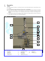
4
Description
4.1
Outline
During operation the Hoist is controlled by means of the mobile Hand Control at the Switchbox on the
cable bin.
An Overspeed Governor prevents a free-fall from a drive or brake failure.
Floor Stops may be fitted to the Hoist to allow stops at a pre-determined point. Pressing the UP button
slightly will cause the Hoist to stop automatically at the next Floor Stop fitted. Pressing the UP button
completely will cause the Hoist to rise continuously until the button is released or the Working Limit is
reached.
Landing Gates interlocks and signalling system connected to the Hoist operate on 48vAC and do not
require additional insulation (see AS 3000 Wiring Rules)
4.2
General Arrangement
10
11
9
8
7
6
12
5
13
4
3
2
1
Fig. 2: Hoist Components
1
Hoist Base
2
Cable Drum
3
Switchbox
4
Hand Control
5
Trailing Cable
Form 0503
Geda Hoist Instructions
6
7
8
9
10
Overspeed Governor
Motor/Brake
Cable Guide
Landing Stop
Working / Final Limit
Issued 14th May 2013
dimensions 1.8 x 2.3m
11
12
13
Mast Section
Platform
Loading Ramp
Page 3 of 6
4.3
Controls
Fig.3: Operator’s Hand Control
Fig. 4: Switchbox at the Hoist base.
1: EMERGENCY
STOP
2: not used
3: UP button
4: DOWN button
5: Control Lead
4.4
1: Main key
switch
2: Green Lamp
(Hoist run)
3: Red lamp
(Hoist stopped,
Interlock open)
4: Cabinet
Lock
5: Red Lamp
(Hoist stopped.
Landing Gate
open)
6: Landing
Gate Link
(48vAC)
Travel Limit Switches
Normal operational up travel is limited by a Working-Limit switch activated by a red plate fitted to the
mast above the topmost landing point [Fig. 6]. This limit switch will be reached if the UP button is
completely pressed, or the UP button is pressed in AUTOMATIC mode while the platform is at the
uppermost landing. Pressing the DOWN button in either mode will allow the platform to descend off this
limit switch.
Down travel is limited by a Working-Limit switch activated by a plate fitted to the mast so the platform
stops at ground level. Pressing the UP button in either mode will allow the platform to move off this limit
switch.
An upper Final-Limit switch is tripped by the red activating plate [Fig. 6] fitted to the mast above the
topmost landing point. The Final-Limit switch will only be tripped by failure of the Working-Limit
switch. It is not possible for the Operator to move the platform off this limit switch and Conveying and
Hoisting Solutions Pty Ltd must be contacted for corrective action.
A Proximity switch is also fitted to limit upper travel if the red Limit switch activating plate is removed or
tampered with.
If the red Limit switch activating plate and Proximity switch are tampered with or removed, the hoist
design will ensure the drive sprocket will over-run the mast but the platform will be retained on the mast
by all keepers and guides.
A lower Final-Limit switch is tripped if the hoist over-runs the lower Working-Limit switch. The Operator
cannot move the hoist platform if this switch has been activated and Conveying and Hoisting Solutions
Pty Ltd must be contacted for corrective action.
Failure, removal or tampering with the Working-Limit and Final-Limit switches in the down direction will
result in the drive pinion causing a special section of rack to be torn off, preventing any hoist operation
until the Supplier has been contacted for corrective action.
Automatic Landing stop may be set by fixing a Landing Stop plate on the mast as shown in Fig. 5
Fig 5: Landing Stop
Fig. 6: Working / Final-Limit
1,05m
Form 0503
Geda Hoist Instructions
Issued 14th May 2013
Page 4 of 6
5
Operation
5.1
Pre-Operation
Read the Warning notices in Chapter 2 and implement a Risk Assessment before starting work
Perform maintenance as described in Chapter 6
Do not work beneath; step over or into the Hoist.
Always wear personal protective equipment.
5.2
Prohibitions
Do not hoist people or animals.
Do not exceed the loading specifications stated in Chapter 3
Do not operate with the load on one side of the platform only or a load protruding over platform edges.
Do not operate in wind speeds of more the 70km/hr
Do not operate if the Hoist or any of it’s components are damaged
Do not operate if required Maintenance has not been performed.
Do not use this Hoist if there is any damage or unusual performance. Isolate the Hoist as described in
Chapter 7.1 Emergency Shutdown.
Do not operate the Hoist if there is a risk of people being endangered by the load or platform.
Do not operate in poor conditions (below 15ºC or above 45ºC, fog, ice, naked flames etc)
Do not operate if upper and/or lower Travel Limit switches have not been set.
Do not operate if any bracing or fixings have been loosened or removed.
5.3
Beginning of Work Period Start-up
Turn the Keyed Isolator Switch [#1 in Fig.4] on the Switchbox to “ON”
Check that the platform is unloaded.
Check that personnel and/or animals are not near or on the platform.
Check all ramps and covers are closed firmly.
Turn the EMERGENCY STOP [#1 in Fig. 3] button clockwise to release.
Verify that the green lamp [#2 in Fig. 4] is lit. See Chapter 5.5 if not lit.
Press and hold the black UP button [#3 in Fig. 3] to raise the platform 2 metres.
Release the button and check the Hoist stops instantly and the platform does not descend under it’s own
weight.
Press and hold the black DOWN button [#4 in Fig. 3] and lower the platform 1 metre.
Release the button and check the Hoist stops instantly and the platform does not descend under it’s own
weight.
Lower the platform to the ground and place a suitable load on the platform.
Repeat the above lift test
Check that the Trailing Cable [#6 in Fig.1] winds and unwinds regularly from its container.
5.4
Loading or Unloading the Platform
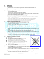
Fig. 7: Prohibited loading
Refer to Fig. 7
The load platform must always be loaded in such a way that
there is free access for loading and unloading.
The load must be evenly distributed on the platform.
Bulky goods must not protrude laterally over the platform.
The load must be positioned securely. Materials that tend to slip,
or is higher than the platform or could fall over, must be
adequately secured.
Consideration should be given to the effects of sudden wind
gusts on the security of the load.
5.5
Indicator Lamps
The green lamp {#2 in Fig. 4] is lit when all Hoist & Landing Gate Interlocks are closed and all
Emergency Stop switches have been released.
The top red lamp {#3 in Fig. 4] is lit when a Hoist Interlock is open such as a Loading Ramp. The Hoist
will not run.
Both red lamps [#3 and #5 in Fig. 4] are lit when a Landing Gate is open, the Landing Gate connection to
the Hoist is loose, unplugging or removing the Landing Gate link or the Emergency Stop Button [#1 in
Fig. 3] has been pressed on the Hand Control. The Hoist will not run.
Form 0503
Geda Hoist Instructions
Issued 14th May 2013
Page 5 of 6
5.6
Regular Operation
Refer to Fig. 3 and Fig 4 in Chapter 4
1. Turn on the Main Key Switch [#1 in Fig. 4]
2. Turn the EMERGENCY STOP Button [#1 in Fig. 3] clockwise to release.
3. Check the green lamp is lit [#2 in Fig. 4]. Refer to Chapter 5.5 if not lit.
4. Firmly press and hold the UP [#3 in Fig. 3] button to cause the platform to rise.
5. Release the button to stop.
6. Firmly press and hold the DOWN [#4 in Fig. 3] button to cause the platform to lower.
7. Release the button to stop.
8. Up and down motions may be ceased at any time by releasing the motion button or by pressing the
EMERGENCY STOP [#1 in Fig. 3] button.
9. Up and down motions will be limited by a Limit Switch – see Chapter 4.4
5.7
Floor Stop Operation
Refer to Fig. 2, Fig. 3 and Fig. 5
Automatic stop at the next landing is available in the UP mode only. Operation in the DOWN mode will
cause the platform to descend from a point to the ground.
Automatic stop at the next landing will occur if:
A Landing Stop has been fitted to the mast [#10 in Fig.2, Fig. 5]
The UP button is pressed slightly
Release the button to stop.
6
Operator Maintenance
6.1
Daily
Perform an empty test run and check that:
Working-Limit switches top and bottom are functioning
Loading ramps lock correctly and the Hoist does not function if opened
EMERGENCY OFF button is functioning and the Hoist does not move
When electrically connected to the Hoist, an open Landing Gate will not allow Hoist operation
6.2
Fortnightly or after Adverse Weather Conditions
Brake test. Load the platform with a load equal to the rated capacity and check that the platform does not
move downward when the Hoist is not operated.
Lubricate the toothed rack and driving pinions with general grease.
Check the trailing cable, mains supply and control leads for damage.
7
Shutdown
7.1
Emergency Shutdown
Stop operation of the Hoist by either:
1. Releasing the UP or DOWN buttons [see Fig. 3].
2. Pressing the EMERGENCY-OFF button [#1 in Fig. 3].
3. Turning off the power supply [#1 in Fig. 4].
Remove the power supply from the Hoist.
Erect a sign stating “DO NOT USE – HOIST UNDER REPAIR” and fix to the Hoist.
Inform management or management’s agent of the situation.
7.2
End of Work Period / End of Hire Shutdown
Unload the Hoist and lower the platform to the ground.
Turn the keyed Main Isolator to “OFF” and withdraw the key [#1 in Fig. 4].
Remove the power supply and secure the key in a safe place.
Clean any dirt or grease from the Hoist.
8
Installation and Removal
Refer to Form 0504 for Installation and Removal Instructions
Form 0503
Geda Hoist Instructions
Issued 14th May 2013
Page 6 of 6