1
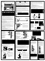
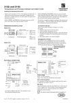
DI6AC Logic Input
DI4Voltage Source
Inputs
Contact Inputs
Externally Powered
DI4
1
3 4
1
A link must be
fitedin place of
external voltage
supply
C C C
C
V+ V+ C C
C V+ C 2
1
C
3 4
2
C C C
Voltage
Supply
C
4
C
3
C 4
L5 N5 L6 N6
1
L3
N5 L6
1
RLY
C C C
C
4 6 8
2
1C2
* This supply is an
external power supply
to power plant devices.
For power rating see
Technical Specification
for the module.
Appendix A.
3 4
2
1
5 7
+
4
3C4
A1 A2 A3 A4
Functional Isolation
To additional
Modules
C4
-
Basic 50V
Isolation
C
1
C
C
2
C
3
A1 B1
4
A2 B2
A3 B3
B4 A4 C4
Relays shown in
relaxed state
e.g. (power off)
4
3C4
3
Label fitted to the side of the relay
module with space to record which
snubbers have been removed
B1 B2 B3 B4
V+ V+ C C
V+ V+ C C
+
2
1
C
3
4
Logic Outputs
+
+
5
Note: Negative logic inputs can be connected if required.
Reverse the polarity of the input connections.
5C6
6
7C8
2
8
+
+
7
AI2 - TC, DC, mA
If the AI module is configured as thermocouple input on one channel and
mV input on the other then the Thermocouple MUST be connected to
channel one.
The shunt option has 5Ω reisitors mounted on the PCB. The mV option
may also be used for mA inputs if fitted with suitable external 5Ω burden
resistors. It permits a 0-20mA input to provide a full-scale range of
0-100mV.
Dual 2, 3, 4-wire
platinum Resistance
Thermometer (PRT)
3
N2
Functional Isolation
Dual thermocouple
(T/C)
2
2
Relay Output
D4
1C2 3C4 5C6 7C8
+
Contact Inputs
2)
1
6 8
1C2
3
Logic Inputs
1)
Logic Outputs
Voltage
Supply +
N4
N1 L2
5 7
4
2
RLY4-
DI8
3
1
N6
N3 L4
Contact
Inputs
1C2 3C4 5C6 7C8
C
L1
3
DI8
L1 N1 L2 N2
L5
To Additional
Modules
C 2
1
DI6
L3 N3 L4 N4
V+ V+ C C
V+ V+ C C
C
D04-
Voltage Source
Inputs
115 and 230 Volt AC
Inputs
DI4
2
DI8-
Dual Potentiometer
Input
Basic 50V
Isolation
5
5C6
6
Basic 50V
Isolation
7
7C8
2
8
AI3 - mA
4-20mA self
powered inputs
Thermocouple
(T/C)
Milli-volts
(mV)
Voltage, mA
Contact Inputs
Logic Inputs
AI3
Dual Volts (V) or
Milli-volt (mV)
A02-V, mA
AI4 - Tc, mV, mA
4-20mA module
powered inputs
+
+
Fuses
The fuses supplied for the relay units are 3.15A (T type),
20mm to EN60127
AI3
AI-TC
A02
AI-TC
Dual milli-amps (mA) High impedance
Shunt Option
Input
(Zirconia Probe)
SHUNT
AI2
AI2
AI2
AI2
AI2
AI2
P1 P2 P3
P1 P2 P3
C1 C2 C3
C1 C2 C3
I1 I2 I3
I1 I2 I3
P1
5Ω
5Ω
P2
mA
mA
mV
C1
mA
C2
I1
P3
C1
I3
+
H1 B1 H2 B2
H1 B1 H2 B2
H1 B1 H2 B2
H1 B1 H2 B2
I1 D1 I2 D2
I1 D1 I2 D2
I1 D1 I2 D2
I1 D1 I2 D2
I1 D1 I2 D2
A1 C1 A2 C2
A1 C1 A2 C2
A1 C1 A2 C2
A1 C1 A2 C2
1+ 1- 2+ 2+
+
A1 C1 A2 C2
I1
A1C1
A2 C2
I2
PRT
OR
A1C1
+I1
A1
-C1
-C1 +A1 -C1
+H1
PRT
I2 B2
+A1
-C1
mA
mV
V
OR
PRT
Reinforced
insulation
I1 B1
OR
A2 C2
+I1
A1
-C2 +A2 -C2
+H2
-C1
V
PRT
mV
+A2
-C2
mA
+A2
Zr
-C2
+
+
mV
RV
RV
RI
mA
mV
2-
1- 2+
1+
3-
1- 3+
1+
2-
1- 2+
1+
mV
mV
C3
1+ 1- 2+ 24-
2- 4+
2+
mA
C2
+
H1 B1 H2 B2
1+ 1- 3+ 3-
1+ 1- 3+ 3-
I2
mA
mA
mV
C3
2+ 2- 4+ 4-
2+ 2- 4+ 4-
RI
mA
Voltage mode:
The input impedance ‘Rv’ of the device connected
to the analogue output module
must be >2KΩ for 10V range.
Current mode:
The input impedance (or loop impedance) ‘Ri’ of
the device connected to the analogue output
module must be <600Ω
Functional insulation
This is defined as: Insulation between conductive parts that is necessary only for the
proper functioning of the equipment. This does not necessarily provide protection
against electric shock.
Reinforced insulation
This is defined as: Insulation between conductive parts, which provides protection
against electric shock.
For 2-wire PRT link A & C
Installation Safety Requirements
Various symbols are used on the instrument, they have the following
meaning:
!
Caution (refer to the
accompanying documents)
Functional
(ground) earth
Protective earth
terminal
Personnel
Installation must only be carried out by qualified personnel..
Enclosure of live parts
To prevent hands or metal tools touching parts that may be electrically live,
the controller must be installed in an enclosure.
Blank Terminal Unit
Bases are supplied to hold 2, 4, 8 or 16 modules. In the event that a base is
not fully populated a blank terminal unit, part number 026373, will be
supplied with the system. It is important that this is fitted into the position
immediately to the right of the last module in order to maintain IP20 rating.
Caution: Live sensors
The controller is designed to operate with the temperature sensor connected
directly to an electrical heating element. However you must ensure that
service personnel do not touch connections to these inputs while they are
live. WIth a live sensor, all cables, connectors and switches for connecting the
sensor must be mains rated.
Wiring
It is important to connect the controller in accordance with the wiring data
given in this instruction sheet. Take particular care not to connect AC
supplies to the low voltage sensor input or other low level inputs and
outputs. Only use copper conductors for connections (except thermocouple
inputs) and ensure that the wiring of installations comply with all local wiring
regulations. For example in the UK use the latest version of the IEE wiring
regulations (BS7671). In the USA use NEC Class 1 wiring methods.
Power Isolation
The installation must include a power isolating switch or circuit breaker. This
device should be in close proximity (1 meter) to the controller, within easy
reach of the operator and marked as the disconnecting device for the
instrument.
Earth Leakage Current
Due to RFI Filtering there may be an earth leakage current of up to 3.5mA.
This may affect the design of an installation of multiple controllers protected
by Residual Current Device (RCD) or Ground Fault Detector, (GFD) type
circuit breakers.
Overcurrent Protection
It is recommended that the DC power supply to the system is fused
appropriately to protect the cabling to the units. The 2500 provides a fuse on
the IOC Terminal Unit to protect the supply from a fault within the 2500.
Voltage Rating
The maximum continuous voltage applied between any of the following
terminals must not exceed 264Vac:
·
DI6 input or RLY4 relay output to logic, dc or sensor connections;
·
any connection to ground
The controller should not be wired to a three-phase supply with an
unearthed star connection. Under fault conditions such a supply could rise
above 264Vac with respect to ground and the product would not be safe.
Conductive Pollution
Electrically conductive pollution must be excluded from the cabinet in which
the controller is mounted. To secure a suitable atmosphere in conditions of
conductive pollution, fit an air filter to the air intake of the cabinet. Where
condensation is likely, include a thermostatically controller heater in the
cabinet.
Installation requirements for EMC
To ensure compliance with the European EMC directive certain installation
precautions are necessary as follows: For general guidance refer to
Eurotherm Controls EMC Installation Guide, HA025464. When using relay
outputs it may be necessary to fit a filter suitable for suppressing the
emissions. The filter requirements will depend on the type of load. For
typical applications we recommend Schaffner FN321 or FN612.
MODEL 2500 DIN RAIL
CONTROLLER
INSTALLATION AND WIRING INSTRUCTIONS
WHAT IS THE 2500?
The 2500 is a modular system which can provide multi-loop PID control,
analogue and digital I/O, signal conditioning and computational blocks with
a variety of plug-in modules.
I/O Control Moduel (IOC)
Always mounted in the left
hand position
Communications
port (RS485/422)
2500M Plug-in I/O Modules
Can be mounted in any order
Plant and Process Connections
2500B Base
The base unit (2500B) can be provided in different sizes, with up to 16 I/O
modules. The base can be mounted on DIN rail (35mm top-hat), or just
bolted to a wall.
Terminal units (2500T) clip into the base, providing customer cconnections to
and from the plant devices and interconnections between modules and the
Input Output Control module (IOC). Terminal units are specific to particular
modules. I/O Modules (2500M) clip into the Terminal Units. These modules
are dedicated to specifc functions- analogue or digital, input or output. The
IOC module (2500E or 2500C) contains the configuration for the system and
communications support. Three communications versions are available for
Modbus, Profibus or DeviceNet.
The system requires 24Vdc at less than 100mA module. A suitable power
supply is 2500P available in 2.5, 5 or 10 amp versions.
Part No. HA027773 Issue 3.2 Jan-04
The Base
!
To mount the base
This unit is intended to be mounted within an enclosure, or in an environment
suitable for IP20 rated equipment. It can be DIN rail or bulkhead mounted.
A
4
4
3
DIN rail
4
Side cover
5
Retention clip
6
Support for
7
Connecting the 24Vdc Power Supply
6
terminal
7
EMC earthing
3
B
3
1
1
1
2
2
E
C
2
D
5
Protective earth
Model
2500B
S02
S04
S08
S10
S12
S16
The Configuration Port
CAUTION
Do not operate the equipment without a protective earth conductor connected to
one of the earth terminals on the base unit. The earth cable should have at least the
current rating of the largest power cable used to connect to the unit.
Connect the protective earth with a suitable tinned copper eyelet, and use the screw
ans washer supplied with the base unit, tightened to a torque of 1.2Nm (910.5lbin).
This connection also provides a ground for EMC purposes.
For DIN rail mounting, use symmetrical DIN rail to EN50022-35 X 7.5 or 35 X 15
mounted horizontally or vertically.
A
87
137
239
289
340
442
Dimensions (mm)
B
C
D
E
180
180
180
180
180
180
5
5
5
5
5
5
68
68
68
68
68
68
15
15
15
15
15
15
Weights (Kgms)
No
All
models models
fitted
fitted
0.6
1.0
0.6
1.0
1.1
1.7
1.3
1.9
1.6
2.1
2.1
2.7
DIN Rail Mounting (horizontal)
1. Mount the DIN rail horizontally, using suitable bolts.
2. Ensure that the DIN rail makes good electrical contact with the metal base
of the enclosure.
3. Loosen screws (1) in the base, and allow them, and the associated base
retention clips (2) to drop to the bottom of he screw slot.
4. In the back of the base is an extruded slot which locates with the DIN
rail(3).
5. Fit the top edges of this into the top edge of the DIN rail (3).
Slide the screws (1) with the associated clips (2) upwards as far as they will
go towards the top of the screw slots. The angled edge of the base
retaining clip (2) must locate behind the bottom edge of the DIN rail.
6. Tighen the screws (1).
DIN Rail Mounting (vertical)
Caution! It is acceptable to mount the 2500 base vertically. If it is mounted
vertically, however, it is advisable to fit a fan in the cubicle to ensure a free
flow of air around the modules.
1. Mount the DIN rail vertically, using suitable bolts.
2. Ensure that the DIN rail makes good electrical contact with the metal base
of the enclosure.
3. Loosen screws (1) in the base, and move them and the associated base
retention clips (2) to the bottom of the screw slot.
4. In the back of the base is an extruder slot which locates with the DIN rail
(3)
5. Fit the top edge of this into the top edge of the DIN rail (3)
6. Slide the screws (1) with the associated clips (2) upwards as far as they will
go towards the top of the screw slots. The angled edge of the base
retaining clip (2) must locate behind the bottom edge of the DIN rail.
7. Tighten the screws.
Caution: Before proceeding with any wiring on this unit, please read section on
Wiring, and Safety and EMC information. It is the responsibility of the installer to
ensure the safety and EMC compliance of any particular installation.
The power supply is the 2500P. This is a DIN rail mounted unit, which may be
mounted adjacent to the 2500 base or remotely. Alternatively, an existing power
supply may be used provided it meets the specification below.
The IOC terminal unit contains a fuse and a reverse biased power diode. If the
power is wired reverse polarity the fuse will blow and protect the complete 2500
base from damage. The fuse is not user replacable. The unit should be returned to
the factory for replacement.
Power supply specification
Power supply voltage:
Supply ripple:
Power consumption:
18.0Vdc min to 28.8Vdc max
2Vp-p max
90W max. per base
Communications
Ports (RS485)
Moulding Modbus
colour
Black
8
8
Label
Push to lock into place
MB120
AN100
120Ω 5%
9 way connector
X
2500A/CABLE/CONFIG/RJ11/9PINDF
6
- +
Optional Power Supply
24VPower and cable to enable
Supply
IOC to be configured
remotely
Modbus
Profibus
DeviceNet
8 7 6 5 4 3 2 1
8 7 6 5 4 3 2 1
8 7 6 5 4 3 2 1
P O 32 16 8 4 2 1
64 32 16 8 4 2 1
BAUD 32 16 8 4 2 1
Switch
position
ON
To Fit a Module
P E Modbus Address
Modules are locked into position
using the retaining lever on the face
of the module.
The module must be fitted and
removed with the lever in the open
position, as shown in this side view.
Once fitted the lever is closed to
securely lock the module in place.
Baud rate
Baud rate is set by the Profibus
Master which is able to detect
the fastest Baud at which all
slaves can operate. The
Profibus IOC is capable of
operating at 12Mbaud.
Ethernet
D O 32 16 8 4 2 1
D DHCP enabled
D DHCP disabled
D Modbus Unit ID
OFF
Addresses from 1 to 63 are set on the rightmost 6 switches.
The leftmost switch may be used to enable DHCP Ethernet addressing.
If all switches are off, the Modbus address and DHCP enable will be
determined by the value seen in the iTools Operator.
Colour
Orange/white
Orange
Green/white
Blue
Blue/white
Green
Brown/white
Brown
2500A/TERM/PROFIBUS/RJ45
24V power
supply terminals
Moulding Profibus
colour
Grey
8
8
+24V 0V
Label
1
DeviceNet Communications
The DeviceNet Communications
IOC is identified by the front label
and the order code printed on the
side label. This IOC must be used
with the DeviceNet Terminal Unit.
The DeviceNet Connector is selected
to comply with the Devicenet Open
Connector specification (5-way,
5.08mm pitch).
ProfiBus - 9 Pin connectors communications line terminators.
For 9 pin D connectors standard ProfiBus cables should be used. These cables have
special headers on the 9 pin D male connector which allow one or two cables to
be connected into them and have a small termination load built in with an ON/OFF
switch, which is set to ON at the two ends of the link.
The ProfiBus standard states that two types of cable, ‘Line A’ and ‘Line B’, may be
used. The termination details for these two types of cable are shown below:
8
6
3
220Ω
390Ω
Profibus Line A
5
8
390Ω
Address
Switch
5
4
3
2
1
390Ω
Profibus Line B
}
}
Profibus RJ45 type - built-in communictions line terminators
RS422-RS485 Modbus communications selection
Fit both links:
1 - 2 for 2 (3) wire Modbus (default)
2 - 3 for 4 (5) wire Modbus
Fit both links:
1 - 2 to terminate the Profibus network
2 - 3 no termination
Note: Earlier units were fitted with a
single link for 2(3) wire or no link for
4(5) wire.
1
2
3
Unit
address
switch
Fit suitable termination ONLY on the last
device in the chain.
On earlier units the use of the termination plug is recommended on later units
fit either the termination unit or both
links in position 1 & 2.
Note: Earlier units were fitted with a
single link. On these units this link has no
function and the system should be
terminated using the termination plug.
Ethernet Communications
The Ethernet IOC is defined by
the front label and the order
code printed on the side label.
This IOC must be used with the
Ethernet Terminal Unit.
The Ethernet port is a 10baseT
port and can be connected to a
hub or switch with Cat5 cable via
the standard RJ45 connector.
Alternatively, an RJ45 cross-over
cable may be used to connect
direct to a pc 10baseT network
Interface Card.
Module
connector
6
3
150Ω
180Ω 1%
180Ω 1%
130Ω 1%
PROFI
1
Profibus 9-pin D-Type Connections
390Ω
Signal
Date ‘N’
Date ‘P’
Gnd
+15V
-
Profibus 9-pin D-Type Connections
9-way D-Type
Communications
Connector
Connections to the Network Connectors
The 9 pin D-Type connector is intended for installations using standard Profibus
cables:
Pin No.
Signal Name
Meaning
1
Shield
Shield (ground)
2
Not used
3
RxD/TxD-P
Receive/Transmit - Data ‘P’
4
Not used
5
DGND
Data ground
6
VP
Voltage - Plus
7
Not used
8
RxD/TxD-N
Receive/Transmit - Data ‘N’
9
Not used
5
Switch
position
ON
8 7 6 5 4 3 2 1
RJ45 pin
1
2
3
4
5
6
7
8
Address
Switch
OFF
Addresses from 0 to 63 can be set.
SW7 SW8 Communications speed
0
0
125K baud
0
1
250K baud
1
0
500K baud
1
1
Both speed and node
address controlled
software
The switch gives 127
addresses from 1 to 127.
Address 0 is invalid.
Switch 8 is not normally
used.
If, however, it is set to ON
the unit address is settable
over communications.
Sixty-three Modbus addresses
can be set in binary using
positions 1 to 6.
Parity has three possible
states - none/even/odd
- using SW7 & 8 as above.
If the address switch is set to
all OFF then the IOC expects
to have it address set by the
configuration tools. For
addresses between 65 and
255 the address switch must
be set all OFF and the address
set in iTools.
Module
connector
RATE DeviceNet Address
Profibus Address
P=Parity on, P=Parity off,
O=Odd, E=Even
120Ω 5%
Fit suitable termination ONLY on the
last device in the chain.
The use of the termination plug is
recommended.
The plastic cover supplied
must be fitted over the
RJ11 socket when the connector
is not in use.
IOC Terminal unit Address Switches
100Ω 5%
1
S
C
PC used for
configuration
Locate the location tab on
Terminal unit with the
matching slot in the base
Push to
release
The terminator is plugged into the last RJ45 socket in the chain. If the
operating interface is a PC or PLC this should be terminated in accordance
using the appropriate load resistors.
Unit
address
switch
1 Screen
2TX
3RX
7 0V
IOC
}
}
}
}
2500A/TERM/MODBUS/RJ45
1
2
3
Screen
+24V 0V
Conections to the Network Connectors
RJ45 pin
Colour
EIA485
2 wire
4 wire
1
Orange/White
B
DTX2
Orange
A
D+
TX+
3
Green/White
Gnd
Gnd
Gnd
4
Blue
5
Blue/White
6
Green
Gnd
Gnd
Gnd
7
Brown/White
B
RX8
Brown
A
RX+
Screen
Modbus RJ45-Type Connections
WARNING CABLE COLOURS MAY CHANGE!
Modbus - RJ45 Communications Line Terminator
The communications line must be terminated using the appropriate load
resistors. To minimise on site wiring and to provide the correct resistor values,
‘Terminator’ are available from Eurotherm.
1
Pin connections on 25
way D-type into PC
1
Profibus DP and DPv1 Communications
Address
Switch
Pin connections on 9
way D-type into PC
3 TX
2RX
5 0V
Configuration Connections
To Fit Terminal Unit
There are two ProfiBus TU
LED Status
options: a standard 9-Way
Indicators
D-type, and a dual RJ45 unit.
The latter is similar to the
Modbus terminal unit, but must
not be confused; the Modbus
unit includes capacitors that
Configuration
could affect high-speed data.
Port (RS232)
Configuration
Port (RS232)
Pin connections RJ11
into IOC
6 no connection
5 RX
4 TCX
3 0V
2 no connection
1 24V (in)
Screen
Assembling I/O Modules & Terminal Units
The Modbus network
connection (RJ45 sockets)
and the 2500 system power
connections (standard
screw terminals) are
provided by the Terminal
Unit.
The network connection to
an operator interface unit,
a PC running iTools or 3rd
party system, or to link
further slave 2500
controllers or other
Modbus equipment in a
system. The IOC can be
configured from the
Modbus network if
required.
Module
connector
Connections to this socket are given below:
Voltage
polarity
of socket
Modbus Communications
I/O Module
interconnection
bus
The IOC will not control the process if:
1. It is in configuration mode or standby mode
2. A network watchdog time-out occurs (if configured)
3. It is removed from the system
Under these conditions all modules will enter a ‘safe’ state. Generally this
defaults as digital output modules will go to an OFF state, and analogue output
modules will go to a minimum output state (generally 0V or 4mA). Unless set
otherwise in the configuration.
Note:- The current taken by each module is 100mA on average.
18V is the absolute lower limit. The use of an 18V power supply with any
appreciable voltage drop may cause unpredictable or out of specification operation.
Direct Panel Mounting
1. Remove the screws (1) and base retention clips (2)
2. Hold the base horizontally or vertically on the panel and mark the position
of the two holes on the panel.
3. Drill two 5.2mm holes in the panel.
4. Using M5 bolts supplied, secure the base to the metal panel.
LED Status
Indicators
An RS232 configuration port is provided on the front of the IOC, via a RJ11
socket. When the IOC is powerd up with a PC connected to the RJ11
configuration port, it will start in configuration mode. Alternatively, the IOC is
put into configuration mode by setting a command from the configuration
software.
Note:- Existing configuration mode must be done using iTools or through
communications.
Module
connector
5-way
DeviceNet
Communications
Connector
Address
Switch
24V power
supply terminals
RJ45 Socket
+24V 0V
The mating DeviceNet connector
(female Open Connector) is supplied to
facilitate screwing user wiring. The pin
functions are marked on the TU.
Pin Number
1
2
3
4
5
Function
V+
CAN_H
DRAIN
CAN_L
V-
DeviceNet Terminators
The DeviceNet specification states that
the bus terminators should not be
included as any part of a master or
slave. They are not supplied as part of
the 2500 DeviceNet termination
assembly.
24V power
supply terminals
Connections to the RJ45 Socket
The RJ45 socket is connected
according to the Ethernet standard.
RJ45 pin
1
2
3
4
5
6
7
8
!
Colour
Orange/white
Orange
Green/white
Blue
Blue/white
Green
Brown/white
Brown
Signal
TX+
TXRX+
RX-
CABLE COLOURS MAY
CHANGE