1
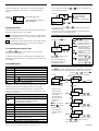
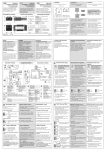
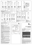
2132i and 2116i
Temperature and Process Indicator and Alarm Units
Installing and Operating Instructions
Thank you for choosing the 2132i or 2116i indicator and alarm unit. It
will provide accurate measurement and display of temperature and
other process variables with up to two alarm outputs for operator alert
and process protection.
Models 2132i/ND and 2116i/ND are Indicator only units which
come without the alarm relay output or logic I/O fitted. Alarms can
still be configured and flashed as messages in the main display but
they will not be able to operate a physical output.
Models 2132i/AL and 2116i/AL are Indicating alarm units which
come with an alarm relay output and logic I/O fitted.
The indicator is supplied configured according to the ordering code
given on page 5. Check the coding on the side labels to determine
the configuration of your particular indicator.
DIMENSIONS AND INSTALLATION
Model 2132i
48mm (1.89in)
103mm (4.01in)
Panel cut-out
mm
2132
24mm
(0.95in)
-0.0 +0.3
OP1
OP2
22.2
-0.0 +0.6
x 45
Latching ears
Inch
Panel retaining clips
-0.0 +0.1
0.88
-0.0 +0.02
x1.77
Model 2116i
48mm (1.89in)
103mm (4.01in)
To install the indicator
Please read the safety information on pages 5 & 6 before
proceeding.
1. Prepare the panel cut-out to the size shown.
2. Insert the indicator through the cut-out.
3. Spring the panel retaining clips into place. Secure the indicator
in position by holding it level and pushing both retaining clips
forward.
4. Peel off the protective cover from the display
Unplugging the indicator
The indicator can be unplugged from its sleeve by easing the
latching ears outwards and pulling it forward out of the sleeve.
When plugging the indicator back into its sleeve, ensure that the
latching ears click into place to maintain the IP65 sealing.
Recommended minimum
spacing of indicators in
both sizes
Panel cut-out
2216
OP1
48mm
(1.89in)
OP2
SP2
REM
45 x 45mm
D
MAN
-0.0 +0.6
10mm
(0.4in)
1.77 x 1.77in
RUN
HOLD
-0.00 +0.02
38mm
(1.5in)
(Not to
scale)
Panel retaining clips
Latching ears
ELECTRICAL CONNECTIONS
External Relay
module
Model 2116i
L
N
External
Relay module
AA
OR
Alarm
ack/reset
Alarm
ack/reset
Logic*
I/O
OR
Logic*
I/O
1B 1A
+
-
V+ AB AA
N
T/C
24
Neutral
mA
Line
85-264Vac
1B -
V-
Relay*
Output
2.49Ω
Pt100
Sensor
input
mA
Over current protection
Use a maximum 2A fuse for the indicator supply and relay output.
A suitable fuse is EN60127 (type T).
20-29Vac/dc
Pt100
V+
20-29Vac/dc
Output ratings
Relay: 2A, 264Vac resistive
Logic: 9Vdc, 12mA (non-isolated from sensor input).
L
Relay*
Output
1A +
24
24
T/C
Model 2132i
Sensor input
V-
AB
Low voltage supply
Line
85-264Vac
Neutral
24
Wire Sizes
The screw terminals accept wire sizes from 0.5 to 1.5 mm (16 to 22
AWG). Hinged covers prevent hands or metal making accidental
contact with live wires. The rear terminals screws should be
tightened to 0.4Nm (3.5lb in).
Low voltage supply
2.49Ω
*Not fitted in indicator only units. Also terminals 1A and
1B not fitted in indicator only unit.
This indicator meets the European directives on safety and
EMC
ENG
Issue 3, Nov-98. Applies to software versions 1.3 & 1.4
-1-
HA026248
OPERATION
TO VIEW THE DISPLAY UNITS
Switch on the indicator. Following a 3 second self-test sequence,
you will see the display shown below. It is called the HOME
display.
Press and release quickly the
will be flashed for 0.5sec
OP1
OP2
* See HOME display options for
other possibilities
and
together will return you to
If you get lost, pressing
the HOME display.
If, at any time, no key is pressed within 45 seconds, the display
will always return to the HOME display.
The indicator has three internal ‘soft’ alarm setpoints which can be
attached to either the logic or relay outputs.
OP1 will flash when an alarm attached to the logic output becomes
true. (This is normally alarm 1). It will go steady when the alarm
is acknowledged but still true.
HOME DISPLAY OPTIONS
Quickly press
OP2 will flash when an alarm attached to the relay output becomes
true. (This is normally alarm 2 or 3). It will go steady when the
alarm is acknowledged but still true.
TO ACKNOWLEDGE A NEW ALARM
Meaning
0;
or
Press
to return to the
HOME display
The Process value will be
displayed
Alarm 2 setpoint will be
displayed and can be
adjusted by
0;D)
To prevent an Operator
changing this option, see
“To Hide Parameters” .
or
The Process value will be
displayed with Alarm 2
setpoint viewed and
adjusted by
or
Pressing
or
displays )O6
to indicate that this a list heading
Alarm 1 is active and it is a High alarm.
Alarm 2 is active and it is a Low alarm.
0.5 sec
Alarm 2 is active and it is a High alarm.
J
Alarm 3 is active and it is a Low alarm.
Sensor Break: Input sensor is open circuit or high
resistance. Check the sensor.
There are three
alarm setpoints.
The first character
is the alarm
setpoint number,
the next three the
alarm type, as
follows:
B) Low alarm
B# High alarm
Diagnostic alarms
Meaning and (Action)
Electrically Erasable Memory Error:
A parameter value has been corrupted.
Contact Eurotherm Controls.
Hardware error:
( Return for repair)
Low display range exceeded: (Check input signal)
High display range exceeded: (Check input signal)
If an alarm has
been disabled, it
will not appear in
this list.
(Return for repair)
Error 2: RAM self-test fail.
(Return for repair)
Error 3: Watchdog fail.
(Return for repair)
Error 4: Keyboard failure. Stuck button, or a button
was pressed during power up.
Error 5: Input circuit failure. (Return for repair)
Power failure. The line voltage is too low.
Issue 3, Nov-98. Applies to software versions 1.3 & 1.4
2 secs
2nd
press
1st
press
The table above shows normal process alarms. In the event of a
failure in the indicator or the sensor the following diagnostic alarm
messages are provided.
Error 1: ROM self-test fail.
The HOME display will be
blank and only alarm
messages will be flashed
The
button steps through parameter list headings. The first list
is the alarm setpoints. The other lists are shown on the next page.
Alarm 1 is active and it is a Low alarm.
In addition to the above messages, the displayed process value will
flash if the input signal or the displayed value is out of range.
55
0=5D
./.
0;
TO CHANGE THE ALARM SETPOINTS (TRIP LEVELS)
Process Alarms
#<D5
))))
####
55
55
55
55
to select:
or
Not used by indicator
Not used by indicator. (Only
applies to software version 1.4)
)D0
ALARM MESSAGES
Message
6
0
2 secs
O0
In addition to the OP beacons, alarm messages are flashed in the
main display. The tables below list all of the possible messages and
their meaning.
D5
Press
twice
and
together. This will also reset any latched
Press
alarms that are no longer true.
Message
Degrees Centigrade
Degrees Fahrenheit
Kelvin
Linear inputs - no units displayed
or
ALARM INDICATION
)
#
)
#
)
D5
J
J'
J
J
The process value (PV)*
button. The display units
Display Units
0.5 sec
Output 1
Output 2
or
)O6
)
Next list
Press
Alarm 1
BBB
Press
or
to
change the setpoint.
Alarm 2
BBB
or
to
Press
change the setpoint.
Alarm 3
)
Press
or
to
change the setpoint.
Press
and
together to return
to the HOME display.
-2-
HA026248
PARAMETER LISTS
TO HIDE PARAMETERS OR MAKE THEM READ-ONLY
Use these lists to change: • The alarm setpoints •The alarm setpoint
limits •User calibration.
HOME
List
X2
Input
List
Alarm
List
Setpoint
List
)
0
O1
BBB
BBB
)
#@
1 )
0 #
O)6
%J
,;
)D0
)
0.6D)
D)
0.6D#
D#
/
!/6/
Access
List
X2
O0
Selecting and adjusting a parameter
1.
2.
Press
to step across the list
headings.
to step down the
Press
parameters within a particular list.
You will eventually return to the list
heading.
*BBB
*
BBB
)
#@
0 )
0 #
O0
Default setting
See HOME
display options on
page 2
0;
Alarm setpoints
Adjustable Range
Default setting
Alarm 1 setpoint
Between low
Alarm 2 setpoint
and high
Alarm 3 setpoint
setpoint limits
Alarm Hysterisis
B PV units
Adjustable Range
Default setting
Between Process
As per order
Setpoint high limit
Value min & max
code
Input List
Adjustable Range
Default setting
O)6
%J
,;
)D0
)
Input filter time in secs
BD
B units
D
0.6D)
D)
0.6D#
D#
Low calibration point
See User
Low point offset
Calibration
Access list
Calibration password
Calibration type.
B
6 (Factory)
85 (User)
High calibration point
High point offset
Example: High alarm 2 has been selected.
or
When
is pressed, instead of
displaying the parameter value, its
availability to Operator is shown as follows:
)65 The parameter will be alterable
05/ The parameter will be ‘promoted’
into the HOME list
5 The parameter will be read-only
#O The parameter will be hidden.
!/6/
Press
until you reach the list
heading
until you reach !/6/
Press
or
to select 15
Press
Press
to return to Operator level
USER CALIBRATION
Setpoint low limit
mV input at the rear terminals
or
Use
to select O6 level.
Other options are:
05 For Operator level
9)) Shows the ‘Full’ set of
available parameters
/. Gives access to
configuration level.
Repeat for all the parameters you wish to hide or make readonly then return to operator level:
05
Setpoint limits
Cold junction temperature at the rear term’ls
or
Press
to enter the password.
The factory default is 1. 0 will be
displayed when the correct password
has been entered.
You are now in Edit level. Press
and
to select a parameter in the normal way.
#
Selectable options
Process value offset
Press
#O
*In place of dashes, the last three letters indicate the alarm type:
)= Low alarm. #=High alarm
1
/
Press
to view the value of a selected parameter. Keep pressing
to increase the value.
)
0
Press to return to the Access list header.
4.
O0
to reach the Access List Heading.
Press
!/6/
to view the value of a
Press
selected parameter. Keep pressing to
decrease the value.
HOME display options
Press
O6
3.
Parameter tables
HOME Home List
Read-only
Read-only
6
Your indicator has been calibrated for life against known
reference sources in the factory. User calibration allows
you to apply offsets to compensate for sensor and other
system errors. The parameter in the N0 list applies a
fixed offset over the whole display range. You may also
apply a 2-point calibration as follows:
until you reach the O0 list
•
Press
until you reach the )D0 parameter
•
Press
or
to enter the password. The factory
•
Press
default is 3. 0 will be displayed when correct.
to reach the ) parameter
•
Press
or
to select 85 (6 will restore
•
Press
the factory calibration)
•
Apply 2-point calibration as below:
User calibration
Displayed Value
D#
Factory calibration
D)
Used for re-configuring the indicator.
Issue 3, Nov-98. Applies to software versions 1.3 & 1.4
0.6D)
-3-
0.6D#
Factory
calibration
HA026248
CONFIGURING THE INDICATOR
Linear input scaling (-12.00 to +80.00mV)
Displayed value
N.0D) mV input low
Select configuration level to change: •The display units •The
input sensor type •The scaling of linear inputs •The alarm
configuration • The passwords.
N.0D#
;)D)
;)D#
To select configuration level
Press
Press
Use
!/6//.
or
)
) to step across the configuration list headings.
N.6 O0
)
?O6 0 Having selected a list heading, press
within a particular list. Press
and
65)
Instrument list
Options
to select a parameter
to change the setting.
Centigrade
J
Fahrenheit
J
Kelvin
J'
None (for linear inputs)
./.
None
....
Decimal places
One
...D.
in display
Two
..D..
)
Always set to )
Control type
Selecting .D or 0O will convert the indicator into a
Sensor Input
Input type
%
Cold junction
compensation
N,0
Sensor break
input impedance
Options
Meaning
)
#
:
#O
)/
./
@
,.
./
@
The alarm is disabled
Low alarm
High alarm
Deviation band alarm
Deviation high alarm
Deviation low alarm
Non-latching
Special - Not used
Latched (manual reset)
No blocking
Blocked until first good
Alarm latching
)/
Alarm blocking
Relay and Logic input/output Configuration
The and lists attach the three internal alarms to the relay
and logic outputs. The logic can be configured as an alarm output
or as an alarm acknowledge input.
O
Display units
Meaning
J thermocouple
&D6
K thermocouple
(D6
L thermocouple
)D6
R thermocouple
5D6
B thermocouple
D6
N thermocouple
.D6
T thermocouple
6D6
S thermocouple
D6
Platinell II
0) 56
100Ω Pt thermometer
D6
Custom input- C=st’d
,;
Linear mV
OFF - Linear inputs only
Automatic
96/
J, J or J external ref.
96/ = 1.5KΩ, #O=5KΩ,
#O#O= 15KΩ
Meaning
Logic output
Relay
5)A
Logic
)/!
Digital output
Function
O!
Alarm Ack input
Logic only D)
Functions: #6, ), 5D and 55 are not
Identity of output
Passwords
0
D0
.D0
)D0
Passwords
Range
Default
Full and Edit level password
Configuration level password
User calibration password
B
B
B
To leave Configuration level
?O6@
Continued in next column....
Issue 3, Nov-98. Applies to software versions 1.3 & 1.4
Options
Relay output
used by the indicator and require separate instructions
No change
O!D Digital output functions
./$
Clear all
Any combination of alarms
)5
alarms
can be attached to the logic or
Alarm 1*
DD)
and
relay output. Press
Alarm 2*
DD#
to select a desired alarms
Alarm 3*
DD)
After a two second pause the
DD5 Sensor
display blinks and returns to
break
O!D. Pressing
and
again will show two decimal
points in those alarms that
.=
New alarm
have been added to the output
Functions: )5, ), ,., ., & 6,!, to 6," are
not used by the indicator and need separate instructions
Normal
./5
. Sense of the output.
Inverted
O.: = output de-energised in N.:
alarm.
*The last three letters will correspond to the alarm type set in the )
list. If the alarm is disabled, ) or ) or ) will be shown.
controller which requires separate instructions.
O.06
Options
)6$
9.
Meaning
The parameters that follow, (6, 0D65 and 0=5), are not used
by the indicator and require separate instructions.
O0
N.1D#
The above sequence is repeated for ) & ) (Alarms 2 & 3)
Limited by display range
1D)O Alarm setpoint O
limits
Limited by setpoint limits
/.
Press to enter configuration level.
D0
N.1D)
Alarm 1
Not used
in the
indicator
or
Use
to enter the configuration
level password. The factory default is 2.
0 will be displayed when the
correct password has been entered.
/.0
9.O6
mV
Alarm list
to select /.
Press
N.6
;)D)
Displayed value high
Alarm Configuration
The ) list configures the three internal ‘soft’ alarms and causes
the appropriate alarm message to be flashed in the HOME display.
or
Use
to enter the password.
The factory default is 1. 0 will be
displayed when the correct password
has been entered.
/0
.
Displayed value low
to reach the Access List Heading.
Press
Press
;)D#
mV input high
-4-
Press
to reach the ?O6 display
Press
or
to select @ After 2
secs the display will blink and return to
the HOME display in Operator level.
HA026248
ORDERING CODE
The indicator is supplied configured according to the ordering code shown below.
Model
number
Function
Supply
voltage
Manual
Logic
I/O
Alarm
Relay
Output
Sensor
input
Setpoint
min
Setpoint
max
Units
External
relay
module
Input
adaptor
2132i
2116i
Function
Indicator only*
Indicating alarm
unit
ND
AL
VH
VL
Sensor input
Supply voltage
85-264Vac
20 -29V dc or ac
XXX
ENG
FRA
GER
NED
SPA
SWE
ITA
Manual
None
English
French
German
Dutch
Spanish
Swedish
Italian
Logic I/O
XX
Disabled*
Logic input
AC
Alarm ack/reset
KL
Keylock
Non-latched alarms
FH
High alarm 1
FL
Low alarm 1
Latched alarms
HA
High alarm 1
LA
Low alarm 1
NW
New alarm
Alarm Relay Output
XX
Disabled*
Non-latched alarms
FH
High alarm 2
FL
Low alarm 2
AL
High alarm 2 &
low alarm 3
Latched alarms
HA
High alarm 2
LA
Low alarm 2
AA
High alarm 2 &
low alarm 3
NW
New alarm
Display range and
Setpoint min & max limits
°C
°F
-210 to 1200
-340 to 2192
-200 to 1372
-325 to 2500
-200 to 400
-325 to 750
-200 to 900
-325 to 1650
-200 to 1300
-325 to 2370
-50 to 1768
-58 to 3200
-50 to 1768
-58 to 3200
0 to 1820
32 to 3308
0 to 1369
32 to 2496
Thermocouples
J
Type J
K Type K
T Type T
L Type L
N Type N
R Type R
S Type S
B Type B
P Platinell II
Resistance thermometer
Z Pt100
-200 to 850
-325 to 1562
Custom downloaded inputs
C Type C -W5%Re/W26%Re
0 to 2319
32 to 4200
(default custom sensor)
D Type D - W3%Re/W25%Re
0 to 2399
32 to 4350
E E thermocouple
-200 to 999
-325 to 1830
1 Ni/Ni18%Mo
0 to 1399
32 to 2550
2 Pt20%Rh/Pt40%Rh
0 to 1870
32 to 3398
3 W/W26%Re (Engelhard)
0 to 2000
32 to 3632
4 W/W26%Re (Hoskins)
0 to 2010
32 to 3650
5 W5%Re/W26%Re (Engelhard)
10 to 2300
50 to 4172
6 W5%Re/W26%Re(Bucose)
0 to 2000
32 to 3632
7 Pt10%Rh/Pt40%/Rh
200 to 1800
392 to 3272
8 Exergen K80 I.R. Pyrometer
-45 to 650
-49 to 1202
Process inputs (linear)
M -9.99 to +80mV
Scalable -999 to 9999
Y 0 to 20mA
Scalable -999 to 9999
A 4 to 20mA
Scalable -999 to 9999
V 0 to 10Vdc (input adapter required)
Scalable -999 to 9999
Input Adaptor
XX
None
V1
0-10Vdc
A1
0-20mA sense
resistor (2.49Ω.
0.1%)
External relay module
XX
Not fitted
R7
Fitted (Operated
by the logic
output)
C
F
K
X
Units
°C
°F
Kelvin
Linear input
*If ‘ND’ (Indicator only) is
specified in the function field,
then XX must be entered in
the Logic I/O and alarm 2
relay fields.
TECHNICAL SPECIFICATION
Display
Supply voltage
Operating ambients
Storage temperature
Output ratings
Calibration accuracy
Cold junction compensation
Input filtering
EMC standards
Safety standard
Atmosphere
Panel sealing
4 digit, green. 10mm high characters
High voltage unit: 100Vac -15% to 240Vac +10%, 48-62Hz. Power consumption: 5Watts maximum
Low voltage unit: 24Vdc or ac -15%, +20% DC to 62Hz, Power consumption: 5Watts maximum
o
0 to 55 C. 5 to 95%RH, non condensing
o
o
-30 C to +75 C.
Relay(isolated): Maximum: 264Vac, 2A resistive. Minimum: 12Vdc, 100mA
Logic I/O: 9Vdc at 18mA (non-isolated from sensor input). Can be used as alarm output or alarm acknowledge
input
± 1 C or ±0.25% of reading whichever is greater
TM
>30 to 1 rejection of ambient temperature change. Uses INSTANT ACCURACY cold junction sensing
technology to eliminate warm-up drift and respond rapidly to ambient temperature changes.
Off to 999.9 seconds
Generic emissions standard EN50081-2 and immunity standard EN50082-2 for industrial environments
EN 61010. Installation category II. (Voltage transients on the power supply must not exceed 2.5kV). Pollution
degree 2. All isolated inputs and outputs have reinforced insulation to protect against electric shock.
Not suitable for use above 2000m or in explosive or corrosive atmospheres
IP65 (EN 60529), or NEMA 4X
o
SAFETY AND EMC INFORMATION
Safety
GENERAL
This indicator complies with the European Low Voltage Directive
73/23/EEC, amended by 93/68/EEC, by the application of the
safety standard EN 61010.
The information contained in these instructions is subject to change
without notice. While every effort has been made to ensure the
accuracy of the information, Eurotherm Controls shall not be held
liable for errors contained herein.
Electromagnetic compatibility
Unpacking and storage
This indicator conforms with the essential protection requirements
of the EMC Directive 89/336/EEC, amended by 93/68/EEC, by the
application of a Technical Construction File. This indicator
satisfies the general requirements of the industrial environment
defined in EN 50081-2 and EN 50082-2.
Issue 3, Nov-98. Applies to software versions 1.3 & 1.4
-5-
The packaging should contain the indicator, two panel retaining
clips, a 2.49Ω current sense resistor and this instruction leaflet.
If the packaging or the indicator are damaged, do not install the
product but contact your nearest Eurotherm Controls agent.
Continued on the next page
HA026248
SERVICE AND REPAIR
Wiring
This indicator has no user serviceable parts. Contact your nearest
Eurotherm Controls agent for repair.
Wire the indicator in accordance with the wiring data given in
these instructions. Take particular care not to connect AC supplies
to the low voltage sensor input or logic outputs. Only use copper
conductors for connections, (except thermocouple). Use a
2
minimum of 0.5mm or 16swg wire for plant connections. Ensure
that the installation complies with local wiring regulations.
Caution: Charged capacitors
Before removing the indicator from its sleeve, switch off the
supply and wait two minutes to allow capacitors to discharge.
Failure to observe this precaution may damage the indicator or
cause some discomfort to the user.
Power Isolation
The installation must include a power isolating switch or circuit
breaker that disconnects all current carrying conductors. The
device should be mounted in close proximity to the indicator,
within easy reach of the operator and marked as the disconnecting
device for the indicator.
Electrostatic discharge precautions
When the indicator is removed from its sleeve, it is vulnerable to
damage by electrostatic discharge from someone handling the
indicator. To avoid this, before handling the unplugged indicator
discharge yourself to ground.
Voltage rating
Cleaning
The maximum continuous voltage applied between any connection
and ground must not exceed 264Vac.
Do not use water or water based products to clean labels or they
will become illegible. Isopropyl alcohol may be used to clean
labels. A mild soap solution may be used to clean other exterior
surfaces of the product.
Safety Symbols
For the above reason the indicator should not be wired to a three
phase supply with an unearthed star connection. Under fault
conditions such a supply could rise above 264Vac with respect to
ground and the product would not be safe.
The following safety symbols are used on the controller:
Conductive pollution
Caution. Refer to the
accompanying documents
Personnel
Electrically conductive pollution (for example carbon dust) must
be excluded from the cabinet in which the indicator is mounted.
Where condensation is likely, for example at low temperatures,
include a thermostatically controlled heater in the cabinet.
Installation must be carried out by qualified personnel.
Installation requirements for EMC
Enclosure of live parts
•
The indicator must be installed in an enclosure to prevent hands or
metal tools touching parts that may be electrically live.
•
!
Caution: Live sensors
The logic input/output is electrically connected to the sensor input
(e.g. thermocouple). In some installations the temperature sensor
may become live. The indicator is designed to operate under these
conditions, but you must ensure that this will not damage other
equipment connected to the logic input/output and that service
personnel do not touch this connection while it is live. With a live
sensor, all cables, connectors and switches for connecting the
sensor and non-isolated inputs and outputs must be mains rated.
For general guidance refer to Eurotherm Controls EMC
Installation Guide, HA025464.
It may be necessary to fit a filter across the relay output to
suppress conducted emissions. The filter requirements will
depend on the type of load. For typical applications we
recommend Schaffner FN321 or FN612.
Routing of wires
To minimise the pick-up of electrical noise, the sensor input wiring
should be routed away from high-current power cables. Where it is
impractical to do this, use shielded cables with the shield grounded
at both ends.
INTERNATIONAL SALES AND SERVICE
EUROTHERM CONTROLS LTD
Faraday Close, Durrington, Worthing,
West Sussex BN13 3PL
Telephone Sales: (01903) 695888
Technical: (01903) 695777
Service: (01903) 695444
Fax (01903) 695666
For countries not listed enquiries/orders to:
Eurotherm Controls Limited,
Export Dept,. Faraday Close, Durrington,
Worthing, West Sussex, BN13 3PL
Telephone (01903) 268500
Fax (01903) 265982
DENMARK
Eurotherm A/S
Telephone Copenhagen (+45 31) 871622
Fax (+45 31) 872124
IRELAND
Eurotherm Ireland Limited
Telephone Naas (+353 45) 879937
Fax (+353 45) 875123
NORWAY
Eurotherm A/S
Telephone Oslo (+47 66) 803330
Fax (+47 66) 803331
FRANCE
Eurotherm Automation SA
Telephone Lyon (+33 478) 664500
Fax (+33 478) 352490
ITALY
Eurotherm SpA
Telephone Como (+39 31) 975111
Fax (+39 31) 977512
Telex 380893 EUROTH I
SPAIN
Eurotherm España SA
Telephone (+34 91) 6616001
Fax (+34 91) 6619093
GERMANY
Eurotherm Regler GmbH
Telephone Limburg (+49 6431) 2980
Fax (+49 6431) 298119
Also regional offices
JAPAN
Eurotherm Japan Limited
Telephone Tokyo (+81 3) 33702951
Fax (+81 3) 33702960
AUSTRALIA
Eurotherm Pty. Ltd.
Telephone Sydney (+61 2) 9477 7022
Fax (+61 2) 9477 7756
HONG KONG
Eurotherm Limited
Telephone Hong Kong (+852) 2873 3826
Fax (+852) 2870 0148
Telex 0802 69257 EIFEL HX
KOREA
Eurotherm Korea Limited
Telephone Seoul (+82 2) 5438507
Fax (+82 2) 545 9758
Telex EIKOR K23105
AUSTRIA
Eurotherm GmbH
Telephone Vienna (+43 1) 798 7601
Fax (+43 1) 798 7605
Telex 047 1132000 EIAUT A
INDIA
Eurotherm India Limited
Telephone Chennai (+9144) 4961 129
Fax (+9144) 4961 831
NETHERLANDS
Eurotherm B.V.
Telephone Alphen a/d Ryn (+31 172)
411752
Fax (+31 172) 417260
BELGIUM
Eurotherm B.V.
Telephone Antwerp (+32 3) 322 3870
Fax (+32 3) 321 7363
Issue 3, Nov-98. Applies to software versions 1.3 & 1.4
NEW ZEALAND
Eurotherm Limited
Telephone Auckland (+64 9) 2635900
Fax: (+64 9) 2635901
-6-
SWEDEN
Eurotherm AB
Telephone Malmo (+46 40) 384500
Fax (+46 40) 384545
SWITZERLAND
Eurotherm Produkte (Schweiz) AG
Telephone Zurich (+41 55) 4154400
Fax (+41 55) 4154415
UNITED KINGDOM
Eurotherm Controls Limited
Telephone Worthing (+44 1903) 269888
Fax (+44 1903) 269666
http://www.eurotherm.co.uk
U.S.A
Eurotherm Controls Inc.
Telephone Reston (+1 703) 787 3405
Fax (+1 703) 787 3436
ENG
HA026248