1
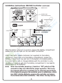
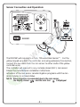
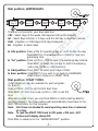
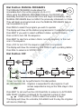
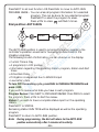
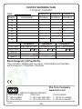
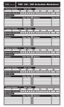
DDCWP™ Series
Waterproof Battery
Controller
INSTALLATION AND
OPERATING INSTRUCTIONS
Thank you for choosing the Toro DDCWP Waterproof Battery
Controller. The DDCWP incorporates the latest programming
technology in an easy-to-use, "digital dial" display.
The following instructions will help you get started. As you
follow the simple steps, please pay attention to the important
NOTES, which will give you helpful hints and programming
advice to maximize the feature capability of the DDCWP.
TABLE OF CONTENTS
Controller Specifications . . . . . . . . . . . . . . . . . . . . . . . .
Installation Instructions . . . . . . . . . . . . . . . . . . . . . . . . .
Sensor Connection and Operation. . . . . . . . . . . . . . . . .
Programming . . . . . . . . . . . . . . . . . . . . . . . . . . . . . . . .
- SET TIME/DAY . . . . . . . . . . . . . . . . . . . . . . . . . . . .
- RUN TIME . . . . . . . . . . . . . . . . . . . . . . . . . . . . . . .
-
WATER DAYS . . . . . . . . . . . . . . .
START TIMES . . . . . . . . . . . . . . .
WATER BUDGET (Season Adjust) .
MANUAL . . . . . . . . . . . . . . . . . .
MANUAL PROGRAMS . . . . . . . . .
.
.
.
.
.
.
.
.
.
.
.
.
.
.
.
.
.
.
.
.
.
.
.
.
.
.
.
.
.
.
.
.
.
.
.
.
.
.
.
.
.
.
.
.
.
.
.
.
.
.
.
.
.
.
.
.
.
.
.
.
.
.
.
.
.
.
.
.
.
.
Page 3
Page 3-4
Page 5
Page 6
Page 6
Page
Page
Page
Page
6
7
7
8
- SYSTEM OFF . . . . . . . . . . . . . . . . . . . . . . . . . . . . .
- AUTO-RUN . . . . . . . . . . . . . . . . . . . . . . . . . . . . . .
Automatic Voltage Detection. . . . . . . . . . . . . . . . . . . . .
Page 8
Page 9
Page 9
Page 10
Page 11
About the DDCWP Memory. . . . . . . . . . . . . . . . . . . . .
Wire Run . . . . . . . . . . . . . . . . . . . . . . . . . . . . . . . . . . .
Custom Watering Plan . . . . . . . . . . . . . . . . . . . . . . . . .
Page 11
Page 11
Page 12
-2-
Controller Specifications:
The DDCWP will run one master valve and one station valve
simultaneously. The DDCWP is a DC controller. This means it ONLY
runs DC latching solenoids. It will not run AC solenoids. It has been
fully tested using Toro DC Latching Solenoids. If you intend to use other
brands, test them before making an installation.
As DC latching solenoids are more susceptible to debris than AC solenoids,
Toro recommends that a filter and master valve be installed in the system.
The DDCWP is tested to be operational under 2 meters of water and is
marked IP68. It is important to completely dry the controller before
opening the battery compartment. It is also important to make waterproof
connections for the longevity of the system components. The DDCWP is
supplied with 3M waterproof connectors for this purpose. If more
connectors are required, Toro recommends 3M DBY type connectors as
these are readily available in most markets.
Connect all field wiring before applying battery power to the controller.
This will insure that all connected DC solenoids are properly calibrated
for operation.
Installation Instructions: DDCWP Controller
Level and mount controller mounting bracket to a solid surface. If
mounting in a valve box, it is suggested to mount the bracket under
the lid and leave sufficient wire so the lid can be removed to access
the controller.
Next connect the solenoid wires to the controller. The controller drives
Toro latching solenoids. It is essential for proper operation that the wire
colors between the solenoid and the controller be matched. The red
controller station wire is connected to the red solenoid wire and the black
controller common wire is attached to the black solenoid wire. It is also
essential that a waterproof wire connection be made. The DDCWP is
shipped with waterproof connectors for this purpose. These can be used
for wire sizes 19 to 26 AWG. (0.9 metric is the largest size wire these
accept)
(continued on next page)
-3-
Installation Instructions: DDCWP Controller (continued)
RESET button
DIGITAL DIAL
Advancement button
WATERPROOF CAP
Attach 2 9VDC
alkaline batteries
black
common wire
orange
master
valve
wire
red
station
wires
yellow rain
sensor wire.
DO NOT CUT IF NOT
CONNECTING TO A
RAIN SENSOR
MASTER
VALVE
C O M M O N
T O
A L L
V A L V E S
After the station wires are connected, remove the battery compartment
waterproof cap and take out the two 9VDC connectors.
Attach two 9VDC alkaline batteries (not supplied) to the battery
connectors, insert them into the battery compartment, replace the
battery compartment cap and turn it clockwise to its locked position.
It is important to add or change batteries with the controller in a dry
condition. If moisture gets into the battery compartment, it can lead to
deterioration of the batteries.
Note: When the controller powers up, it sends an “Off” pulse to all the
solenoids so they are calibrated for proper operation. This is why
the solenoids should be connected prior to attaching the batteries.
If it is desired to program the controller prior to installation, attach
two 9VDC alkaline batteries, program the controller and remove
the batteries before field installation. Then follow the steps above.
-4-
Sensor Connection and Operation:
The DDCWP will respond to a Toro, TRS wired Rain Sensor™. Cut the
yellow looped wire from the controller, and using waterproof connectors,
connect the two wires from the rain sensor to either ends of the yellow
controller wires.
The controller will respond to any normally closed (N.C.) rain sensor.
Follow the manufacturers installation instructions.
Activation of the rain sensor cancels irrigation programs until the rain
sensor returns to a closed status.
NOTE: When irrigation is suspended due to the rain sensor,
the display shows:
and the rain icon
is displayed.
-5-
PROGRAMMING:
It is recommended to press the RESET button to clear the memory.
Press DIAL to advance to SET TIME/DAY
Dial Position: SET TIME/DAY
Set the current YEAR, MONTH, DAY & TIME.
Set the YEAR with +/ON or -/OFF
Press NEXT
Set the MONTH with +/ON or -/OFF
Press NEXT
Set the DAY with +/ON or -/OFF
Press NEXT
Select 24 hour mode (default) or AM/PM with +/ON or -/OFF
Press NEXT
Set the TIME with +/ON or -/OFF
Press NEXT if you wish to go back to YEAR setting.
NOTE: If you press and hold either +/ON or -/OFF continuously, the digits
will advance more quickly.
Press DIAL to advance to RUN TIME
Dial Position: RUN TIME
The DDCWP has 3 independent programs: A, B & C.
Program A has an initial start-up program with each station set for a 5
minute run time and a 0400 (AM) start time. This initial program can be
erased by following the “Program Erase” function described on page 10 or
it can be modified by following these programming steps.
Press PROG to select the program to be set.
Press +/ON or -/OFF to set the desired RUN TIME for the first station.
Run time is in one minute increments from 1 minute to 4 hours.
Press NEXT to advance to next station.
Continue to assign stations to a program by entering RUN TIMES for those
stations. Unselected stations in a program will remain OFF. Enabling /
Disabling MASTER VALVE: After the last station is the MASTER VALVE
position. The display will show “ON”. To disable the master valve / pump
start for this program, press -/OFF. Press +/ON to resume master valve /
pump start operation.
NOTE: To turn off a station which has previously been programmed, press
both +/ON and -/OFF buttons and hold them for a few seconds.
Use this option if you have a station with RUN TIME and you want this station
to be OFF or if you have a start time and you want to cancel it (set it to OFF).
-6-
Dial position: WATER DAYS
Calendar
Prog. A
Intervalr
Prog. A
day
interval
start
Odd
Prog. A
Even
Prog. A
There are 4 choices for your days selection:
CAL - Select days of the week. (All days are ON as the default)
Int - Select days interval, 1-7 days, and the 1st day to start the interval
Odd - Irrigation on Odd days (31st day is skipped)
En - Irrigation on Even days.
In CAL position: Press +/ON for operating day or -/OFF to skip the day.
Press NEXT for Interval selection or DIAL for next programming step.
In "Int" position: Press +/ON or -/OFF to select the watering day interval.
Press NEXT to select the 1st day to start the watering
(using the +/ON or -/OFF buttons).
In Odd position: Press NEXT to select Even days or DIAL.
In Even position: Press NEXT if you wish to go back to CALENDAR.
Press DIAL to advance to START TIME.
Dial position: START TIMES
3 start times per day are available for each program.
(A, B or C)
Press +/ON or -/OFF to set the first start time.
Press NEXT for start 2 and use +/ON or -/OFF to set the
time.
After setting start times, you can Press PROG to start entering data for
another program. The Dial position will automatically move back to the
RUN TIME position for that program.
Note: Start times are stacked to avoid operating more than 2 solenoids
at a time.
Note: To reset the START TIME back to OFF press +/ON and -/OFF
buttons until display shows OFF.
Press DIAL to advance to the “WATER BUDGET” position.
-7-
Dial position: WATER BUDGET (Seasonal adjust)
In this dial position you can increase or decrease the
RUN TIME of all stations in that program by percentage
scaling from 0% to 200% in 10% increments.
Press PROG to select the program you wish to scale.
Press +/ON or -/OFF to change.
The Initial RUN TIME represents 100%. The controller will record the
change, i.e., if a program was scaled down to 80%, next time you enter
this dial position the display will show 80%.
To set a program to "OFF"
If you wish to stop irrigation of a program, set percentage scaling to 0%.
The display will show that program is OFF.
To resume normal operation of that program, Dial to "WATER BUDGET"
and increase the percentage to your desired value. Increasing to 100%
will set RUN TIME to its original value.
Press PROG to select the program.
Press DIAL to advance to MANUAL.
Dial position: MANUAL
The MANUAL mode allows immediate customized
irrigation on one or more zones. You can set an
individual RUN TIME for each of the stations you wish
to start manually. The controller has a "programmable manual" function, so
if you manually operate more than one station, they will open in sequence.
Press +/ON or -/OFF to set the station RUN TIME.
Press NEXT to advance to next station.
To turn ON the 1st station in the sequence:
Press DIAL to AUTO-RUN position.
Press -/OFF (in AUTO-RUN position) to turn OFF the sequence.
All stations with a manually programmed RUN TIME will be displayed.
Operating stations will flash and the display will show the remaining RUN
TIME of the station (count down).
Press DIAL to advance to MANUAL PROGRAMS.
-8-
Dial Position: MANUAL PROGRAMS
The MANUAL PROGRAMS mode allows the
immediate start of an entire program (A, B or C).
When using the MANUAL PROGRAMS feature, the DDCWP will
essentially override the normal start time and begin immediately. Using
MANUAL PROGRAMS does not affect the previously scheduled run times.
They will begin as programmed once the MANUAL PROGRAMS feature
has completed its cycle.
Press PROG to select the program you wish to operate.
The display will show all the stations programmed in the selected program
Press NEXT if you wish to select a different station as the 1st station.
Press +/ON to turn ON the sequence.
Press NEXT to skip from a station that is currently irrigating to the next
one in the sequence.
Press -/OFF to turn OFF the sequence (before it is completed).
The display will show the remaining RUN TIME of each operating station.
Press DIAL to advance to SYSTEM OFF.
Dial Position: OFF
OFF
Rain Delay
All Prog.
0-7 days
Press
Press
Press
Prog. Er.
Prog. Er.
Prog. Er.
Prog. A
Prog. B
Prog. C
3 main functions can be performed in this dial position.
ALL PROGRAMS OFF - Irrigation is suspended for all programs. It will
remain suspended as long as the DIAL stays in this
position.
Press NEXT to set next function OR Press DIAL to advance to AUTO-RUN
RAIN DELAY: Irrigation is delayed for the selected number of days.
Press +/ON or -/OFF to select the number of days.
The display will show the umbrella, DLY=DELAY and the day the irrigation
will resume (Flashing).
-9-
Press NEXT to set next function OR Press DIAL to move to AUTO-RUN
PROGRAM ERASE – You can erase all program information for a selected
program. This can be done for any selected program.
Press NEXT to select the program to erase.
Press +/ON to erase.
will flash 5 times.
Dial position: AUTO-RUN
The AUTO-RUN position is used to provide information regarding the
controller's operation as well as for reviewing all data stored in the
irrigation programs.
The following is a list of information you can observe on the display:
• Current Time & Day
• A program(s) in OFF position
• Information regarding the operating station: program, station and start
times
• Active Rain Delay
• If irrigation is suspended due to SENSOR input
• Low battery state
To turn OFF the working cycle, press DIAL to MANUAL PROGRAMS and
press -/OFF.
If you wish to review what data you have in each program:
Program Review: Press NEXT to PROGRAM REVIEW. Press PROG to select
the program. Press +/ON to start the review.
Status: If you wish to have a complete status report on the operating
station:
Press NEXT to STATUS.
Remaining station RUN TIME will be displayed as well as the operating
program.
Press NEXT to return to AUTO-RUN position.
Note: During programming, the dial will return to the AUTO-RUN
position automatically after 3 minutes of inactivity.
- 10 -
Automatic Voltage Detection
The DDCWP has an automatic voltage detection circuit. Before an
irrigation start is initiated, this circuit checks battery voltage to insure that
there is sufficient voltage remaining to shut the solenoids off. If there is not
sufficient voltage, the program is cancelled and the low battery icon is
turned on in the LCD display. If, during an irrigation programmed start,
voltage falls below a safe level, the program is cancelled and the low
battery icon is turned on.
About the DDCWP memory
This controller is equipped with "on board" back up battery that will keep
the program memory for a few years in case power is not available. The 9
volt battery will turn on both displays and programming is possible.
Maximum Wire Runs for DDCWP Controller
With battery voltage at 9V DC and 7 Bars (105 PSI) of pressure at the
valve, these are the maximum wire runs for an 8 station DDCWP.
AWG # 18 (1.0mm2) multi-strand wire – 60m (197')
AWG # 16 (1.5mm2) multi-strand wire – 100m (305')
AWG # 14 (2.5mm2) multi-strand wire – 150m (493')
AWG # 12 (4.0mm2) multi-strand wire – 250m (820')
The Toro Promise — Limited Two-Year Warranty
The Toro Company and its affiliate, Toro Warranty Company, pursuant to an agreement
between them, jointly warrants, to the owner, each new piece of equipment (featured
in the current catalog at date of installation) against defects in material and workmanship
for a period described below, provided they are used for irrigation purposes under
manufacturer's recommended specifications. Product failures due to acts of God (i.e.,
lightning, flooding, etc.) are not covered by this warranty. Neither Toro nor Toro Warranty
Company is liable for failure of products not manufactured by them even though such
products may be sold or used in conjunction with Toro products. During such warranty
period, we will repair or replace, at our option, any part found to be defective. Your
remedy is limited solely to the replacement or repair of defective parts. Return the defective
part to your local Toro distributor, who may be listed in your telephone directory Yellow
Pages under "Irrigation Supplies" or "Sprinkler Systems," or contact The Toro Warranty
Company P.O. Box 489, Riverside, California, 92502. Phone (800) 664-4740 for the
location of your nearest Toro distributor or outside the U.S., call (909) 688-9221. This
warranty does not apply where equipment is used, or installation is performed, in any
manner contrary to Toro’s specifications and instructions, nor where equipment is altered
or modified. Neither Toro nor Toro Warranty Company is liable for indirect, incidental or
consequential damages in connection with the use of equipment, including but not limited
to: vegetation loss, the cost of substitute equipment or services required during periods
of malfunction or resulting non-use, property damage or personal injury resulting from
installer’s actions, whether negligent or otherwise. Some states do not allow the exclusion
or limitation of incidental or consequential damages, so the above limitation or exclusion
may not apply to you. All implied warranties, including those of merchantability and fitness
for use, are limited to the duration of this express warranty. Some states do not allow
limitations of how long an implied warranty lasts, so the above limitation may not apply to
you. This warranty gives you specific legal rights and you may have other rights which vary
from state to state. The DDCWP controller is covered by this warranty for a period of two
years from the date of installation.
- 11 -
CUSTOM WATERING PLAN
3 Program Controller
Date:
Station
Description
Program A
Program B
Program C
Duration
Duration
Duration
1
2
3
4
5
6
7
8
Irrig. Days
Days Cycle
Start 1
Start 2
Start 3
Program A
Program B
Program C
Su Mo Tu We Th Fr Sa Su
Su Mo Tu We Th Fr Sa Su
Su Mo Tu We Th Fr Sa Su
Odd Even
Odd Even
Odd Even
Electromagnetic Compatibility
This controller complies with European, United States and Australian
electromagnetic compatibility standards.
The Toro Company
www.toro.com
Ask for Customer Service
TORO AUSTRALIA
T: 1300 130898
F: 1300 788144
020205
TORO USA
T: +00 1-951-688-9221
F: +00 1-951-785-3511
- 12 -
TORO EUROPE
T: +00 32-14-562960
F: +00 32-14-581911