1
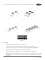
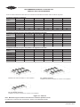
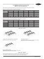
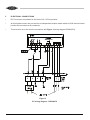
TECHNICAL INFORMATION
OPERATING INSTRUCTIONS
BITZER AUSTRALIA
BUFFALO TRIDENT HEAT EXCHANGE
LDV-D SERIES
- Air Cooled Condensers Models
LDV-D-4R-2F
LDV-D-6R-2F
LDV-D-4R-2F-2M
LDV-D-6R-2F-2M
LDV-D-4R-3F
LDV-D-6R-3F
LDV-D-4R-3F-2M
LDV-D-6R-3F-2M
LDV-D-4R-4F
LDV-D-6R-4F
LDV-D-4R-4F-2M
LDV-D-6R-4F-2M
Content
1
Important Recommendations
2
Safety Recommendations
3
Application Ranges
4
Installation Guide
5 Electrical Connections
6
Commissioning Instructions
7
Maintenance Instructions
8 Decommissioning Instructions
9 Manufacturer
10 Service Address
1
1
Important Recommendations
•
LDV-D air cooled condensers are intended for installation only by Qualified Refrigeration
Personnel and are to be installed in accordance with the guidelines mentioned in this manual.
•
All electrical work is to be carried out by Qualified Electrical Personnel and to be in accordance
with local electrical regulations.
2
Safety Recommendations
•
•
Condensers are supplied with a Nitrogen Holding Charge. (Release pressure fully before
accessing the connection points).
•
During normal operation Pressurised Refrigerant is contained within the condenser. Extreme care
should be taken to avoid leakage, as personal injury may occur. (Avoid the use of sharp objects
in close proximity to refrigeration piping).
Electrical power is to be isolated prior to the commencement of any electrical work.
HXO- 508-1 AUS
•
Extensive gas loss in enclosed area may result in asphyxiation.
•
Contact with refrigerant may cause personal injury (freeze burns).
•
Normal operating conditions involve hot surfaces within the condenser. Extreme care should be
taken to avoid contact.
•
Avoid contact with condenser fins as sharp edges may cause personal injury.
•
Insertion of any object into condenser fans is to be avoided as this may result in personal injury and/or equipment damage.
•
Operating sound pressure levels may cause discomfort. Refer to catalogue for calculated sound
levels.
3
Application Ranges
•
These condensers are intended for use in commercial refrigeration systems with a maximum
operating ambient temperature of approximately 60°C (special designs available on
application).
•
Recommended refrigerants: HFCs, HCFCs (also suitable for CFCs).
•
This series of condenser is not suitable for use with NH3 (Ammonia) or R744 (CO2).
•
Standard condensers are not to be installed in hazardous/combustible environments (special
designs available on application).
4
Installation Guide
The LDV-D Series of Air Cooled Condensers are suitable for Vertical air flow.
a)
Mounting - Vertical Air Flow
•
Remove the condenser from its crate.
•
Vertical air flow condensers are shipped without legs fitted.
•
Legs are supplied within each LDV-D Series condenser crate.
•
Using an appropriate lifting device (refer Figure 1 for recommended lifting methods), attach the
legs to the condenser using the bolt kit supplied.
•
Place the condenser into the installation position and secure using the mounting holes located in
the legs.
2
HXO-508-1 AUS
No. Of Fans
3
4
3 X 2 MODULES
4 X 2 MODULES
LDV-D SERIES
UNIT
DIMENSION "A"
4 FAN
2578mm
Please Note:
6 FAN
2578mm
8 FAN
7922mm
DIM 'A'
1500
3000
1500
3000
Figure 1
• Minimum diameter of fixing bolts is to be 12.70mm (½”)
• The use of lifting devices during installation is recommended where applicable.
• Observe recommended condenser mounting locations as per Figure 2.1 and Figure 2.2.
• Remove the transport brackets from the LDV-D Series condensers.
• Ensure the condenser is installed level, to avoid liquid locking within the condenser..
• Refrigeration piping connections should be carried out in accordance with the current
“Refrigeration Code of Good Practice”* (beware of HOT surfaces present during the welding
procedure).
3
HXO-508-1 AUS
RECOMMENDED MOUNTING LOCATIONS FOR
VERTICAL AIR FLOW CONDENSERS
Note: All clearance dimensions listed below are calculated with standard issue Buffalo Trident condenser legs fitted
Condensers installed on a solid deck
Model/s
Dimensions
(mm)
LDV-D-4R-2F
LDV-D-4R-3F
LDV-D-4R-4F
LDV-D-4R-2F-2M
LDV-D-4R-3F-2M
LDV-D-4R-4F-2M
LDV-D-6R-2F
LDV-D-6R-3F
LDV-D-6R-4F
LDV-D-6R-2F-2M
LDV-D-6R-3F-2M
LDV-D-6R-4F-2M
A
700
900
1000
1000
1300
1500
B
1100
1300
1500
1500
1900
2200
C
900
1100
1300
1300
1600
1800
D
1400
1700
2100
2100
2500
2900
E
900
1100
1300
1300
1600
1800
Condensers installed on an open mesh platform 0.5m high from a solid deck
Model/s
Dimensions
(mm)
LDV-D-4R-2F
LDV-D-4R-3F
LDV-D-4R-4F
LDV-D-4R-2F-2M
LDV-D-4R-3F-2M
LDV-D-4R-4F-2M
LDV-D-6R-2F
LDV-D-6R-3F
LDV-D-6R-4F
LDV-D-6R-2F-2M
LDV-D-6R-3F-2M
LDV-D-6R-4F-2M
A
700
900
1000
1000
1300
1500
B
800
1000
1100
1100
1400
1600
C
900
1100
1300
1300
1600
1800
D
1100
1300
1500
1500
1900
2200
E
1100
1400
1600
1600
2000
2300
Condensers installed on an open mesh platform 1.0m high from a solid deck
LDV-D-4R-2F
LDV-D-4R-3F
LDV-D-4R-4F
LDV-D-4R-2F-2M
LDV-D-4R-3F-2M
LDV-D-4R-4F-2M
LDV-D-6R-2F
LDV-D-6R-3F
LDV-D-6R-4F
LDV-D-6R-2F-2M
LDV-D-6R-3F-2M
LDV-D-6R-4F-2M
A
700
900
1000
1000
1300
1500
B
500
700
800
800
1000
1100
C
900
1100
1300
1300
1600
1800
D
700
900
1000
1000
1300
1500
E
1400
1700
1900
1900
2400
2700
Model/s
Dimensions
(mm)
Figure 2.1 - Part 1/2
Installation with solid air restriction to 1 side of platform
For a multiple condenser:
Installation with solid air restriction to 1 side of 1 end of platform
For an individual condenser:
Installation with solid air restriction to 1 side of 1 end of platform
Figure 2.1 - Part 2/2
Note: Maximum height of solid air restriction from condenser platform is 2.8m.
For alternative condenser deck arrangements, please contact BITZER Australia.
4
HXO-508-1 AUS
RECOMMENDED MOUNTING LOCATIONS FOR
VERTICAL AIR FLOW CONDENSERS
Note: All clearance dimensions listed below are calculated with standard issue Buffalo Trident condenser legs fitted
Condensers installed on an open mesh platform 0.5m high from a solid deck
NOTE: The solid air restrictions are level with the condenser platform
Model/s
LDV-D-4R-2F
LDV-D-4R-3F
LDV-D-4R-4F
LDV-D-4R-2F-2M
LDV-D-4R-3F-2M
LDV-D-4R-4F-2M
LDV-D-6R-2F
LDV-D-6R-3F
LDV-D-6R-4F
LDV-D-6R-2F-2M
LDV-D-6R-3F-2M
LDV-D-6R-4F-2M
700
700
700
800
1000
1600
Dimensions
J
700
(mm)
K
800
1000
1100
1100
1400
L
700
700
800
800
1100
1300
M
1100
1300
1500
1500
1900
2200
N
900
1100
1300
1300
1600
1800
Condensers installed on an open mesh platform 1.0m high from a solid deck
NOTE: The solid air restrictions are level with the condenser platform
Model/s
LDV-D-4R-2F
LDV-D-4R-3F
LDV-D-4R-4F
LDV-D-4R-2F-2M
LDV-D-4R-3F-2M
LDV-D-4R-4F-2M
LDV-D-6R-2F
LDV-D-6R-3F
LDV-D-6R-4F
LDV-D-6R-2F-2M
LDV-D-6R-3F-2M
LDV-D-6R-4F-2M
Dimensions
J
700
700
700
700
700
700
(mm)
K
500
700
800
800
1000
1100
L
700
700
700
700
700
800
M
700
900
1000
1000
1300
1500
N
900
1100
1300
1300
1600
1800
Figure 2.2 - Part 1/2
For multiple condensers:
Installation with a solid air restriction to 1 side and 1 end of platform
Note: Solid air restriction is level with the platform
Installation with a solid air restriction to 1 side of platform
Note: Solid air restriction is level with the platform
For an individual condenser:
Installation with a solid air restriction to 1 side and 1 end of platform
Note: Solid air restriction is level with the platform
Figure 2.2 - Part 2/2
Note: Maximum height of solid air restriction from condenser platform is 2.8m.
For alternative condenser deck arrangements, please contact BITZER Australia.
5
HXO-508-1 AUS
5
ELECTRICAL CONNECTIONS
•
EC Fan motors are suitable for 400 Volt ±10%, 50 Hz operation.
•
All three phase motors are pre-wired to an independent isolation switch within an IP56 rated electrical
junction box mounted on the condenser.
•
These motors are to be wired in accordance with Figure 3 (wiring diagram R55000079).
Figure 3
EC wiring diagram - R55000079
6
HXO-508-1 AUS
6
COMMISSIONING INSTRUCTIONS
•
Leak testing should be carried out in accordance with the current “Refrigeration Code of Good
Practice”*.
•
Following leak testing, the system should be evacuated using accepted refrigeration practices. The
vacuum pump should be connected to both the high and low pressure sides of the system with
all shut-off valves open.
•
Refrigerant charging should be carried out in accordance with the current “Refrigeration Code of
Good Practice”*.
•
Extreme care should be taken to avoid direct contact with liquid refrigerant (freeze burns).
•
Ensure the electrical wiring is in accordance with local electrical regulations and ensure fan
motor direction is correct.
7
MAINTENANCE INSTRUCTIONS
•
Buffalo Trident condensers require low maintenance apart from regular cleaning of the fin face.
Frequency is dependent upon the operating environment of the condenser.
•
It is recommended that fin surfaces are cleaned using a soft bristle brush and/or low pressure water,
taking care to avoid all electrical components (electrical power must be isolated prior to cleaning).
•
All fan motors contain bearings and are maintenance free.
8
DE-COMMISSIONING INSTRUCTIONS
•
Pump down refrigeration system into the receiver or suitable container. (As per “Refrigeration
Code of Good Practice” *)
•
Isolate power and remove electrical wiring (remove earth wire last) and associated components
where necessary.
•
Disconnect refrigeration piping and seal both the system and condenser connections (ensure
that positive/negative pressure does not exist in condenser prior to disconnection).
•
Condenser can now be removed from location (the use of lifting devices during removal is
recommended where applicable).
* “Code of Good Practice” produced in conjunction with AFCAM.
7
HXO-508-1 AUS
9
MANUFACTURER
•
Our products are manufactured in compliance with applicable international standards and
regulations. If you have any questions about how to use our products or if you are planning special
applications please contact:
10
SERVICE ADDRESS
•
For local support please refer to our website www.bitzeravp.com.au for a list of our nearest branch
office.
8
BITZER Australia Pty Ltd
Buffalo Trident Division
25 Strzelecki Avenue
Sunshine VIC 3020, Australia
Tel.: +61 (0)3 8326 8200
Fax: +61 (0)3 9310 2520
Please contact us via email and visit our website:
[email protected]
www.bitzeravp.com.au
HXO-508-1 AUS
NOTES
9
HXO-508-1 AUS
In the interest of continuous improvement BITZER reserves the right to change the specifications or design of any
of its products without notice. The BITZER Symbol, Name BITZER and model numbers are registered trade marks.
All products manufactured are pending design and specification registration and must not be copied or duplicated in
any way.
Please note: The ISO Certification applies to New South Wales and Victoria branches only.
NSW
tel +61 (2) 8801 9300
fax +61 (2) 9673 4698
10
Victoria
tel +61 (3) 8326 8200
fax +61 (3) 9310 2520
SA
tel +61 (8) 8345 6110
fax +61 (8) 8268 4555
WA tel +61 (8) 6350 6297
fax +61 (8) 9359 2077
QLD
tel +61 (7) 3725 1360
fax +61 (7) 3274 3621
NZ
tel +64 9 415 2030
HXO-508-1 AUS