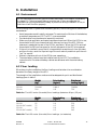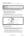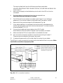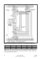
1
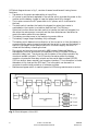
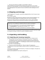
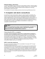
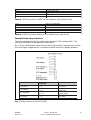
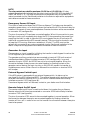
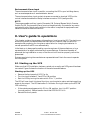
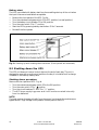
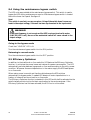
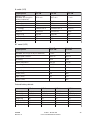
7.5 kVA - 15 kVA UPS
User’s and Installation
Manual
7.5 kVA - 15 kVA UPS
User’s and Installation Manual
1010896
Revision F
CONTENTS
1. Introduction ............................................................................................................. 5
2. System description ................................................................................................... 5
2.1 General description ............................................................................................... 5
2.2 System configuration ............................................................................................. 7
3. Safety information ................................................................................................... 8
4. Shipping and storage ................................................................................................ 9
5. Unpacking and handling ........................................................................................... 9
5.1 Unpacking and incoming inspection .................................................................... 9
5.2 Moving ................................................................................................................. 10
6. Installation ............................................................................................................. 11
6.1 Environment ........................................................................................................ 11
6.2 Floor loading ....................................................................................................... 11
6.3 Power connections .............................................................................................. 12
7. Computer and alarm connections.......................................................................... 16
8. User’s guide to operations ...................................................................................... 19
8.1 Starting up the UPS ............................................................................................. 19
8.2 Shutting down the UPS ........................................................................................ 20
8.3 Control panel functions ....................................................................................... 21
8.4 Using the maintenance bypass switch ................................................................ 22
8.5 Efficiency Optimizer ............................................................................................ 22
9. Maintenance ........................................................................................................... 23
10. Warranty ................................................................................................................ 23
11. Technical specifications ......................................................................................... 23
Copyright 2001
The contents of this manual are the copyright of the publisher
and may not be reproduced (even extracts)
unless permission granted.
Every care has been taken to ensure the accuracy of
the information contained in this manual, but no liability
can be accepted for any errors or omission. The right
to make design modifications is reserved.
1. Introduction
This User’s manual gives basic information about 7.5 - 15 kVA, uninterruptible power
systems: their basic function, their features, how to use them, and what to do in case of
trouble. Instructions for shipping, storing, handling and installing the equipment are
also given.
The planning guidelines of this manual describe only the specific demands of UPS
units. Local legislation and regulations for electrical instruction must be followed in the
UPS installation.
This manual is mainly intended for the chief operator/system supervisor, electrical
consultants and installation electricians.
The UPS system must be installed according to the instructions in this manual. Fixed
installation may be performed by qualified personnel only. Failure to recognise the
electrical hazards could prove fatal.
2. System description
UPS (Uninterruptible Power System) protects different types of sensitive electrical
equipment: computers, workstations, sales terminals, critical instrumentation,
telecommunications systems, process control systems, etc. The UPS protects them from
problems associated with utility power of poor quality, or a complete loss of power.
Sensitive electrical equipment needs protection from electrical interference. Interference
from outside the facility (such as lightning, power company accidents and radio
transmissions) and interference from inside the facility (from motors, air conditioners,
vending machines and arc welders, for example) can create problems in the AC power
line to the sensitive equipment. The problems can be: power outage, low or high
voltage, slow voltage fluctuation, frequency variations, differential and common-mode
noise, transients, etc.
UPS cleans the utility AC power, maintains a constant voltage and if needed isolates the
output to the critical load. These actions help to keep power line problems from
reaching the critical system, where they can damage software and hardware and cause
the equipment to operate erratically.
2.1 General description
This UPS is a double conversion on-line UPS for protection of computer systems and
other intelligent devices such as measurement instruments and industrial automation
applications. It conditions the raw mains and supplies continuous, clean three-phase
power to the critical systems. While feeding the load the UPS also keeps the battery
constantly charged. If utility power fails, the UPS will continue to supply clean power
without any interruption at the UPS output.
If the power failure outlasts the backup time the UPS will shut down in order to prevent
a total discharge of the battery. When the line voltage is restored the UPS will start up
again automatically providing power to the critical load and boost-charging the battery
bank.
1010896
Revision F
7.5 kVA - 15 kVA UPS
User’s and Installation Manual
5
UPS block diagram shown in fig. 1, consists of several modules each having its own
functions:
• Transients on the mains are reduced by an input filter.
• AC-power is rectified and regulated in the rectifier which provides the power to the
inverter and the battery charger to keep the battery bank fully charged.
• The inverter converts the DC-power back to AC-power, which is delivered to
the load.
• The static switch transfers the load to the bypass line when the inverter is
overloaded or the inverter is not able to feed the load. The Efficiency
Optimizer function allows the static switch to transfer the load to the bypass line
also when the mains power is smooth and free from disturbances. See below for
more information about this new feature.
• The battery provides power to the load during a mains failure.
• The battery charger keeps the battery fully recharged.
• The battery switch determines the direction of the current to or from the battery. In
normal mode the mains is supplying the load, the switch is open and the battery is
kept fully recharged. When there is a failure in the mains supply, the switch is
closed and the battery is feeding the load.
• The control and monitoring circuits with ABM-system (Advanced Battery
Management) monitor and control the operation of the UPS-system including
automatic battery test. They show the user the status of the system operation by
visual and audible indicators. The UPS sends information about the system
operation via potential free relay outputs and two serial data interfaces (RS232).
(UPS can be shut down remotely via computer interface.) This information includes
data about utility, load and the UPS itself. The information can be used in a
computer to ensure total protection of software and data.
• Maintenance bypass switch is used to bypass the UPS during maintenance or service.
Fig. 1. Block diagram of the UPS.
6
7.5 kVA - 15 kVA UPS
User’s and Installation Manual
1010896
Revision F
Efficiency Optimizer function
In addition to the traditional on-line operation mode this UPS features the Efficiency
Optimizer function - a new feature adding real cost effectiveness to the UPS. It minimises
the power loss and reduces power consumption. The UPS automatically switches between
bypass and on-line mode according to the utility power condition. Whenever there are
imperfections in the mains supply the UPS feeds power in on-line mode. When mains
power is smooth and free from disturbances the UPS switches automatically to bypass
mode for maximum efficiency. If needed, UPS detects all mains imperfections in a fraction
of a second and turns back to on-line mode. As a result the UPS reaches up to 99% average
efficiency. The Efficiency Optimizer function is standard in this UPS and can easily be
activated. The UPS can of course run permanently in traditional on-line mode if prefered.
All models of 7.5 - 15 kVA UPSs run in the traditional on-line mode as default.
2.2 System configuration
The UPS system consists of the UPS device itself and the internal backup battery. In
addition, several options may be included in the system. The options are used to tailor a
matching solution to fulfil the site and load requirements of the installation.
The main considerations in planning the UPS system are:
• The UPS output power rating (VA) shall be specified according to the total power
demand of the protected system. Some margin should be allowed for potential
expansion of the protected system, and for possible inaccuracy in calculating or
measuring the actual power requirement.
• The battery shall be sized according to the desired backup time. Note that the backup
time is longer if the load is less than the nominal power rating of the UPS.
The following options are available:
• Input filter (THD 10%)
• Output isolation transformer
• External battery cabinets
• Long life (10 years) batteries
• LCD monitor panel
• Remote status panel
• Alarm extension unit
• LanQuattro
The UPS series consists of the following UPS-systems:
Power
7.5 kVA/5.25 kW
10 kVA/7.0 kW
10 kVA/10.5 kW
Backup time
18 / 10 min
14 / 7 min
7 min
R e c h a rg e t i m e
5h
5h
5h
The backup times are for standard batteries and long life 48 pcs. or 32 pcs. batteries. See
the dimensions of the UPS series in figure 2.
1010896
Revision F
7.5 kVA - 15 kVA UPS
User’s and Installation Manual
7
Fig. 2. Dimensions of the UPS.
3. Safety information
Since the UPS unit operates on line power and contains a bank of high-current backup
batteries, the information in this chapter is important to all personnel involved.
Storage and transportation
Because of the high energy stored within the batteries, the UPS equipment must be
handled with care. The UPS must always be kept in the position marked on the package
and must not be dropped.
Installation
Do not operate the equipment in the presence of flammable gases or fumes. Operation of
any electrical equipment in such an environment constitutes a safety hazard. Do not
place the UPS in an airtight room.
The UPS system must be installed according to the instructions in this manual.
Installation may be performed by qualified personnel only. Failure to recognise the
electrical hazards could prove fatal.
WARNING!
Do not open the UPS cabinet! Some components inside the UPS cabinet carry high
voltages. To touch them may prove fatal. All operations inside the unit must be
carried out only by a service engineer from the manufacturer or from an agent
authorised by the manufacturer.
User operations
The only user operations permitted are:
• Starting up and shutting down the UPS unit (not the initial start up).
• Operating the user interface.
• Connecting data interface cables.
8
7.5 kVA - 15 kVA UPS
User’s and Installation Manual
1010896
Revision F
•
Monitoring the UPS with LanSafe III and FailSafe III software.
These operations must be performed according to the instructions in this manual.
During any of these operations, the user must take greatest care, and perform only the
prescribed operations. Any deviation from the instructions could be dangerous to the
operator.
4. Shipping and storage
The UPS equipment is shipped on specifically designed pallets so that it is easy to move
with a forklift.
Do not stack the pallets.
Because of the high energy stored within batteries, the UPS must be handled with care.
The UPS must always be kept in an upright position and must not be dropped.
Because of the heavy weight of the UPS system proper provision must be made for
transportation. See technical specifications for dimensions and weights of the UPS.
If the UPS is not immediately installed the following must be remembered:
• The UPS should be stored in the original packing and shipping carton.
• The recommended storing temperature is between +15°C ... +25°C.
• The equipment must always be protected from moisture and weather.
If the UPS is stored for a longer period of time the batteries of the UPS should be charged
for at least 8 hours every 6 months to maintain the battery condition.
5. Unpacking and handling
5.1 Unpacking and incoming inspection
Unpack the equipment and remove all the packing materials and shipping cartons.
• The equipment must be inspected for damage during shipment. If damage has
occurred during transit, all the shipping cartons and packing materials should be
stored for further investigation. If the damage is visible a claim for shipping damage
must be filed immediately.
To file a claim for shipping damage:
• The carrier must be informed within 7 days of receipt of the equipment.
The equipment must be checked against the packing slip to verify that the shipment is
complete.
The UPS is thoroughly inspected at the factory. If there are no damages or discrepancies,
the installation may proceed.
Removing the equipment from the pallet (see figure 3):
1010896
Revision F
7.5 kVA - 15 kVA UPS
User’s and Installation Manual
9
Removing the UPS from pallet
Fig. 3. Unloading the UPS from pallet
5.2 Moving
The UPS units are equipped with castors, for easy movement. The unit is simply pushed
into place. Because the UPS is heavy, it should be verified that surfaces on which it is
moved are strong enough. When wheeling the UPS, be careful not to tilt it.
10
7.5 kVA - 15 kVA UPS
User’s and Installation Manual
1010896
Revision F
6. Installation
6.1 Environment
All the requirements concerning environment described in this chapter (Installation)
or chapter 11 (Technical specifications) must be met. If they are neglected the
manufacturer cannot guarantee the safety of personnel during installation or use, or
that the unit will function properly.
When locating the UPS system and the battery options, the following points have to be
remembered:
• Avoid temperature and humidity extremes. To maximise the life time of the batteries,
an ambient temperature of 15°C to 25°C is recommended.
• Provide shelter from the elements (especially moisture)
• Make sure that ventilation and space requirements are met. When the UPS is in use,
there should be 100 mm clearance at both sides and on top of the UPS. 100 mm
clearance is needed at the rear of the UPS for ventilation. When the UPS is serviced
there should be 500 mm free space for the left side panel of the UPS to be opened.
• If the unit is installed in a way that it is impossible to access the unit from the sides
and from the top, must the input wiring of the unit make it possible to pull the unit
“out” for service.
• Maintain clearance at front of the UPS for user operations.
• The extra battery cabinet must be installed next to the UPS. The installation
instructions for the external battery cabinet are delivered with the extra battery
cabinet.
6.2 Floor loading
When planning the installation the floor loading must be taken into consideration
because of the heavy weight of the UPS.
The strength of the installation surface must be adequate for point and distributed
loadings given in table 1.
7 . 5 k VA
1 0 k VA
1 5 k VA
We i g h t
(kg)
220/180
220/180
220
Point loading
(kg/cm²)
0.8/0.6
0.8/0.6
0.8
Distributed
loading (kg/m²)
720/580
720/580
720
Table 1a. The UPS series (N-model) floor loadings (batteries 48 pcs / 32 pcs)
7 . 5 k VA
1 0 k VA
1 0 k VA ( N C - m o d e l )
1 5 k VA
1 5 k VA ( N C - m o d e l )
We i g h t
(kg)
95
95
75
95
75
Point loading
(kg/cm²)
0.4
0.4
0.3
0.4
0.3
Distributed
loading (kg/m²)
310
310
245
310
245
Table 1b. The UPS series (N-model) floor loadings (no batteries)
1010896
Revision F
7.5 kVA - 15 kVA UPS
User’s and Installation Manual
11
6.3 Power connections
The electrical planning and the UPS installation must be done by qualified personnel
only.
WARNING!
The UPS contains high voltage and current which can injure or kill personnel and
damage equipment.
The customer has to supply the wiring to connect the UPS to power lines.
The installation inspection and initial start up of the UPS must be carried out by service
engineers from the manufacturer or from an agent authorised by the manufacturer.
The UPS unit has the following power connections:
• 3-phase and N and PE connection for rectifier input
• 3-phase and N and PE connection for bypass input
• 3-phase and N and PE connection for load output
• +, - and PE connection for the battery
All input and output wiring of the UPS connects to the terminals located behind the left side
panel. Wiring can be routed through the cable entry at the bottom or back of the UPS cabinet.
Fig. 4a. Removing the front panels and opening the left side panel.
Mains and load connections
The proper connection order is as follows:
1.
Check that electrical connections to the installation site have been properly executed.
Also check fuse or circuit breaker ratings and cable dimensions against figure 5 or 6.
The figure depends on if you use two cable or single-cable input.
2.
A readily accessible disconnected device must be incorporated in the fixed wiring.
The disconnect device shall have a contact separation of at least 3 mm.
A warning label must be added on all primary power isolators installed remote from
the UPS area to warn electrical maintenance personnel that the circuit feeds a UPS.
12
7.5 kVA - 15 kVA UPS
User’s and Installation Manual
1010896
Revision F
The warning label shall carry the following wording or equivalent:
ISOLATE UNINTERRUPTIBLE POWER SYSTEM (UPS) BEFORE WORKING ON
THIS CIRCUIT
3.
Switch off the supply to the distribution point to which the UPS unit is to be
connected.
4.
For extra safety, also remove the fuses from the selected lines.
Make absolutely sure that there is no power.
5.
The UPS should be connected in accordance with figure 5 or 6. The figure
depends on if you use two-cable or single-cable input. Normal/NC-model.
6.
Remove the front panels and open the left side panel (Fig. 4a).
7.
If two cable installation is considered, the interconnection wires between the
rectifier and the bypass input terminals must be removed. The interconnection
wires are labelled L1, L2, L3.
8.
Connect input cables and output cables to the UPS (Fig 4b).
Note: Make sure that the neutral of bypass input is properly connected.
9.
Make sure that the UPS unit output cable is connected to the load.
10.
Also connect the computer and alarm connections according to chapter 7.
These connections are behind the upper front panel.
11.
If a external bypass switch will be used, take first contact to your dealer.
The UPS unit is now connected to the mains and to the load but there is no power. Make
sure that the connections are properly made.
Fig. 4b. UPS connection locations
1010896
Revision F
7.5 kVA - 15 kVA UPS
User’s and Installation Manual
13
Fig. 5. Five-wire installation of UPS units from 7.5 to 15 kVA with two-cable input.
UPS
7.5 kVA
10 kVA
15 kVA
A
16 A
16 A
25 A
1
2.5 mm²
2.5 mm²
6 mm²
2
2.5 mm²
2.5 mm²
6 mm²
3
2.5 mm²
2.5 mm²
6 mm²
4
6 mm²
6 mm²
6 mm²
Table 2. Fuse and cable dimensions for five wire installations of UPS units 7.5 to
15 kVA using two cable input. Note that the fuse letters and the cable numbers refer
to the letters/numbers in figure 5.
14
7.5 kVA - 15 kVA UPS
User’s and Installation Manual
1010896
Revision F
Fig. 6. Five-wire installation of UPS units from 7.5 to 15 kVA with single-cable input.
UPS
7.5 kVA
10 kVA
15 kVA
A
16 A
16 A
25 A
1
2.5 mm²
2.5 mm²
6 mm²
2
2.5 mm²
2.5 mm²
6 mm²
4
6 mm²
6 mm²
6 mm²
Table 3. Fuse and cable dimensions for five-wire installations of UPS units from 7.5
to 15 kVA using single cable input. Note that the fuse letters and the cable numbers
refer to the letters/number in figure 6.
1010896
Revision F
7.5 kVA - 15 kVA UPS
User’s and Installation Manual
15
External battery connections
The UPS is provided with the connections for external battery cabinet. If external battery
cabinet is used, see the installation manual of the battery cabinet, which is delivered with
the cabinet. External battery cabinets include connection cables when connecting
external battery cabinet next to UPS.
The installation of the external battery cabinet must be done by qualified personel only.
7. Computer and alarm connections
An interface for direct communication with your computer system is supplied in the
UPS unit. The interface consists of two RS232 serial data interfaces, four potential free
relays, Emergency power off input and four programmable auxiliary inputs. Default
values of these auxiliary inputs are: Generator on, Remote output on/off, External bypass
switch and Environment alarm. These interfaces are located behind the upper front
panel (see figure 4b). The UPS is designed to fully comply with LanSafe III and FailSafe
III software. If any software not provided by the manufacturer is used, the pin
configuration should be verified.
NOTE
All connections mentioned in chapter 7 must not be galvanically connected to any
mains connected circuits. Reinforced insulation to the mains is required for
equipments and cables connected to these connections.
Connecting the UPS to a computer
The UPS/PC communicating device is delivered as a complete solution package with
accompanying Power Management Software. To connect the UPS to the computer, use
the communication cable provided with the package. (Note: Do not use any other
communication cable than the one provided with the UPS). Check from the software
documentation that the platform running on your computer is supported. Follow the
instructions of the Power Management Software to complete the installation. For UNIX,
other operating systems, SNMP and more advanced power protection solution
combinations, please contact your local dealer.
RS232 serial data interfaces
Wiring of the serial data interfaces shall be routed behind front panel, NOT through
cable entries of power connections.
The RS232 interface X100 uses 9-pin female D-sub connector and the interface X101 is
9-pin male D-sub connector. The information includes data about the utility, load and
the UPS itself. The connector X100 is to be used with a computer connection and the
other X101 with a computer and a modem connection. See tables 6 and 7 for meaning of
the pins. The RS232 must not be galvanically connected to any mains connected circuits.
Reinforced insulation to the mains is required for equipments and cables connected to
these connections.
16
7.5 kVA - 15 kVA UPS
User’s and Installation Manual
1010896
Revision F
Pin
Pin
Pin
Pin
Pin
1
2
4
8
9
Received data
Tr a n s m i t t e d d a t a
S i g n a l g ro u n d
DC output
U P S g ro u n d
Table 4. RS232 connection (X100) for the computer, 9-pin female D-sub.
Pin
Pin
Pin
Pin
Pin
Pin
1
2
3
4
5
7
Data carrier detected
Received data
Tr a n s m i t t e d d a t a
D a t a t e r m i n a l re a d y
S i g n a l g ro u n d
Ready to send
Table 5. RS232 connection (X101) for the modem, 9-pin male D-sub.
Potential free relay interface
This relay interface uses a 15-pin male D-sub connector (X102, see figures 4b). The
following information is available from these relays:
Pin 15 is the UPS shutdown input. User can send a high level for 5 seconds to turn off the
UPS until proper voltage returns. It is active only when the UPS is in battery operation.
Line failure
Low battery
UPS bypassed
UPS on/ok or
UPS Alarm
Pin no
connected
1-2
1-3
4-5
4-6
10 - 11
10 - 12
7-9
7-8
System state
Line ok
Line failure
Battery normal
Battery low
Inverter supply
Bypass supply
UPS on/ok
UPS alarm
Fig. 7. Relay interface of the UPS (X102).
1010896
Revision F
7.5 kVA - 15 kVA UPS
User’s and Installation Manual
17
NOTE!
The relay contacts are rated for maximum 1 A/30 Vac or 0,2 A/60 Vdc. All relay
outputs are galvanically isolated from the other circuits of the UPS (UPS standards IEC
60950, EN 50091-1-1). The relay contacts must not be galvanically connected to any
mains connected circuits. Reinforced insulation to the mains is required for equipments
and cables connected to these connections.
Emergency Power Off Input
This input is used to shut down the UPS from a distance. This feature can be used for
emergency power down, or for shutting down the load and the UPS by thermal relay for
instance in the event of room overtemperature. Remote shut down wires are connected
on connector X2 (see figure 4b).
The pins of connector X2 have been connected together. When this connection is open,
the logic circuitry will completely shut down the UPS, thus preventing the power from
supplying the load. In order to have the UPS running again the pins of connector X2
have to be connected and the UPS manually started. The pins must be shorted in order
to keep the UPS running. Maximum resistance is 10 ohm. The EPO must not be
galvanically connected to any mains connected circuits. Reinforced insulation to the
mains is required for equipments and cables connected to these connections.
Generator On Input
The generator on input is used for inhibiting the transfer to static bypass line when the
UPS is supplied by an unstable ac source.
The generator auxiliary contact wires are connected on terminal X219 on the control
interface board behind Relay Interface connector X102 (see figure 4b). In normal
operation the pins X219/1 and X219/2 are not to be connected together. When the
connection between these pins are connected together by floating contacts of the
generator control device, the logic circuitry on the UPS will prevent the transfer to
unstable power source. When the unit is delivered the connection on terminal X219
will be open.
External Bypass Switch Input
If the UPS system is equipped with an external bypass switch, its status can be
monitored by the UPS via terminal X221. The external bypass switch auxiliary contact
wires are connected on terminal X221 on the control interface board behind Relay
Interface connector X102 (see figure 4b).
If a external bypass switch will be used, contact to your dealer must first be taken.
Remote Output On/Off Input
The remote output on/off input is used to shut down the inverter from a distance.
Remote output on/off wires are connected on connector X220 behind Relay Interface
connector X102 (see figure 4b).
The pins of connector X220 are not to be connected together in normal operation. When
the connection between these pins are connected together by floating contact the
inverter will turn off. In order to turn on the inverter the connection between these pins
have to be opened.
18
7.5 kVA - 15 kVA UPS
User’s and Installation Manual
1010896
Revision F
Environment Alarm Input
The environment alarm input is used for connecting the UPS to your building alarms,
such as overtemperature or smoke detector alarms.
The environment alarm input contact wires are connected on terminal X222 on the
control interface board behind Relay Interface connector X102 (see figure 4b).
NOTE!
The programmable auxiliary inputs (Generator ON, External Bypass Switch, Remote
Output On/Off, Environment Alarm) must not be galvanically connected to any mains
connected circuits. Reinforced insulation to the mains is required for equipments and
cables connected to these connections.
8. User’s guide to operations
This chapter contains the necessary information on how to use the UPS. The starting up
and shutting down procedures described here are only used on a few occasions for
example when preparing for a long term mains failure or changing the batteries. In
normal operation the UPS runs automatically.
Initial start up is always performed by a service engineer of the manufacturer or by a
representative of an agent authorised by the manufacturer. Otherwise the safety of
personnel during installation or use, or that the unit will function properly, can not be
guaranteed.
During commissioning the manufacturer representative will train the users to operate
the UPS system.
8.1 Starting up the UPS
Make sure that UPS installation has been carried out correctly and UPS ground has been
connected. Figure 8 shows the location of the switches and breakers.
Starting up the UPS
• Remove the front panels of UPS. Fig. 4a.
• Turn the circuit breakers F1 and F2 to ON-position
• Start the UPS by turning the main switch S1 to “I” position
The UPS will now check its internal functions, synchronise to mains and start supplying
power to the output. The UPS starts after 3-4 minutes. During this start up the UPS ON
LED is blinking.
•
•
If the maintenance bypass switch S2 is in ON-position, turn it to OFF-position
(normal position). Before transfer check that UPS ON LED is lit.
Reinstall the front panels
1010896
Revision F
7.5 kVA - 15 kVA UPS
User’s and Installation Manual
19
Battery start
The UPS is provided with battery start function enabling start-up of the unit when
the input lines are not available or acceptable.
• Remove the front panels of the UPS. Fig. 4a.
• Turn the maintenance bypass switch S2 to OFF-position (normal position)
• Turn the battery circuit breaker F2 to ON-position
• Turn the main switch S1 to “I” position
• Start the UPS by pressing battery start button S3 for 2 seconds.
• Reinstall the front panels
Fig. 8. Starting up and shutting down switches. (Front panels are removed.)
8.2 Shutting down the UPS
The UPS unit does not have to be shut down at the end of each day. The unit is
designed to cope with a continuous load from the day it is installed until a change
is needed in the backup battery bank.
Shutting down procedure:
Remove the front panels of UPS. Fig. 4a.
• Turn the maintenance bypass switch S2 to the ON-position.
• Turn the main switch S1 to “ “ position
• Turn the circuit breakers F1 and F2 to “ 0 “ position
• The UPS stops supplying power and it will be disconnected internally
from the batteries.
NOTE!
The load receives its power directly from the power line through the maintenance
bypass switch. High voltage is still present in some parts of the UPS.
20
7.5 kVA - 15 kVA UPS
User’s and Installation Manual
1010896
Revision F
8.3 Control panel functions
The control panel shows the status of the operation and generates an audible alarm if the
user should be alerted. See figure 9.
LED
LED is activated if:
UPS ON
UPS operates normally providing
power to its outlets.
LINE ON
Utility mains voltage is used for feeding
the load. When LED is off, the utility
mains is too low, too high or missing or UPS is not
synchronised to input power lines.
ON BATTERY
UPS is on battery operation. If the LED is
blinking, the battery voltage is low and less than
2-3 minutes back-up time left.
BYPASSED UPS is bypassed.
LOAD
The four LEDs show the load of the UPS.
One green LED: Output is on.
Two green LEDS: The load is more
than 40% of the nominal.
Three green LEDS: The load is more
than 60% of the nominal.
Four green LEDS: The load is more than
80% of the nominal.
OVERLOAD
UPS is overloaded.
OVERTEMP
UPS is overheated.
SERVICE
Service of the UPS is needed.
ALARM
The audible alarm is activated.
Line failure, battery low, UPS by-passed,
overload, overtemperature, service
or UPS alarm.
Fig.9. Control panel
Operating switches
MAIN POWER SWITCH
I/
Starts and stops the UPS.
RESET
Resets the alarms and shuts down
the audible alarm.
Normally the warnings given by the control panel do not mean that the output power is
affected. Instead they are preventive warnings intended to alert the user.
1010896
Revision F
7.5 kVA - 15 kVA UPS
User’s and Installation Manual
21
8.4 Using the maintenance bypass switch
The UPS units are provided with a maintenance bypass switch. This switch is used to
bypass the UPS during maintenance or service. Maintenance bypass switch is located
behind the lower front panel. See figure 8.
Note!
This switch is used only on rare occasions. Using of the switch doesn’t cause any
break in the output voltage, if the unit has been synchronised to the input mains.
WARNING!
If the input frequency is not correct and the UPS is not synchronised to mains
(LINE ON LED is off), the use of the mechanical switch will cause a break in the
output voltage.
Going to the bypass mode
Check that “LINE ON” LED is lit.
Turn the maintenance bypass switch into the ‘ON’ position.
Returning to normal mode
Turn the maintenance bypass switch into the ‘OFF’ position.
8.5 Efficiency Optimizer
In addition to the traditional on-line mode this UPS features the Efficiency Optimizer
function. It minimises the power losses and reduces the power consumption. The UPS
automatically switches between bypass and on-line mode according to the utility power
condition. Whenever there are imperfections in the mains supply the UPS feeds power
in on-line mode.
When mains power is smooth and free from disturbances the UPS switches
automatically to bypass mode. If needed UPS detects all mains imperfections in a
fraction of a second and turns back to on-line mode.
The Efficiency Optimizer function is standard in this UPS and it shall be activated via the
serial interface port during the first start-up situation by the service engineer. If the
Efficiency Optimizer has not been activated, the UPS runs in online mode.
22
7.5 kVA - 15 kVA UPS
User’s and Installation Manual
1010896
Revision F
9. Maintenance
Maintenance of a UPS unit must be performed only by a person who has completed the
UPS service training.
Battery maintenance
The condition of the batteries is crucial to correct operation of the UPS. The UPS units are
provided with the automatic battery test ABM, which continuously controls the condition
of the battery bank. When the capacity of the battery bank has decreased remarkable, the
SERVICE LED starts blinking and audible alarm is activated.
In addition to the automatic battery test it is recommended that a battery discharge test
is done once or twice per year. This test is recommended to be done together with the
preventive maintenance by manufacturer service personnel.
Scrapping the UPS
Before scrapping UPS or its battery cabinet, battery bank and lithium battery on the logic
board must be removed. Due to high energy and high voltage, removal of batteries is
allowed only for authorised service personnel. Local requirements must be followed in
battery recycling or discard.
WARNING!
HAZARDOUS MATERIALS. Batteries may contain HIGH VOLTAGES,
and CAUSTIC, TOXIC and FLAMMABLE substances. Batteries can injure or kill
people and damage equipment if used improperly. DO NOT DISCARD unwanted
batteries or battery material in the public waste disposal system. Follow ALL
applicable, local regulations for storage, handling and disposal of batteries and
battery materials.
10. Warranty
The product is warranted against defects in material and workmanship for a period of
12 months from its original date of purchase.
11. Technical specifications
1. General
1.1 Rated power
1.2 Technology
7.5 kVA, 10 kVA, 15 kVA at p.f. 0,7
On-line, double conversion topology with automatic
bypass switch and maintenance bypass switch.
Frequency independent operation.
2. Input
2.1 Rated voltage
220/380, 230/400, 240/415 Vac; three phase input
2.2 Voltage range
170/294 - 279/484 VAC without depleting battery
196/336 - 279/484 VAC full charge capability
1010896
Revision F
7.5 kVA - 15 kVA UPS
User’s and Installation Manual
23
2.3 Rated frequency
50/60 Hz selectable
2.4 Frequency range for rectifier 45 - 65 Hz
2.5 Nominal/max input current
Three phase
7.5 kVA
10 kVA
15 kVA
2.6 Input power factor
10 A / 14 A
12 A / 16 A
18 A / 22 A
0.96
3. Output
3.1 Nominal voltage
220/380, 230/400, 240/415 VAC, selectable
3.2 Voltage regulation
± 1% static
± 5% dynamic at 100% load change
Response time 1 ms
3.3 Voltage distortion
< 2 % THD linear load
< 5 % THD non linear load
3.4 Frequency
50/60 Hz, selectable
3.5 Frequency regulation
Synchronisation to line, ± 0.5, ± 1.0 or
± 2.0 Hz selectable.
Free-running ± 0.005 Hz
Slew rate 0.5, 1.0, 2.0, 3.0 Hz/sec, selectable
3.6 Over load
101% to 110% for 10 minutes (inverter)
110 - 125% for 60 sec (inverter)
125 - 150% for 30 sec (inverter)
125% continuous (bypass)
150% for 10 min (bypass)
1000% for one cycle (bypass)
4. Environmental
4.1 Ambient temperature
0° ... +40°C operating
+15°C ... +25°C recommended
-25°C ... +55°C storage (without battery)
4.2 Ventilation
Fan cooling, temperature µP monitored
4.3 Altitude
1000 m operating w/o derating
2000 m operating with 10% derating
15 000 m during transportation
4.4 Humidity
15 ... 95% RH, non-condensing
4.5 Audible noise
< 50 dBA at 1 meter distance
4.6 Protection class
IP 20
5. Standards
5.1 Safety
IEC 60950, EN 50091-1-1
5.2 Emissions
5.3 Immunity
EN 50091-2 Class A
EN 50091-2
24
7.5 kVA - 15 kVA UPS
User’s and Installation Manual
1010896
Revision F
N model (UPS)
7.5 kVA
5.25 kW
10.0 kVA
7.0 kW
15.0 kVA
10.5 kW
18/10 min
14/7 min
7/- min
3x65 A
92%
420 W
2x288/2x192 V
3x65 A
93%
490 W
2x288/2x192 V
3x65 A
94%
590 W
2x288 V/-
48/32 pcs
2x24/2x16
2x24/2x16
2x24/-
Weight (kg)
Wi d t h ( m m )
Depth (mm)
Height (mm)
220/180
400
750
700
220/180
400
750
700
220/400
750
700
Output power
Backup time
( s t a n d a rd a n d l o n g l i f e
48/32pcs batteries)
O u t p u t p e a k c u r re n t
E ff i c i e n c y
Power dissipation
DC-voltage
Number of batteries
NC model (UPS)
Output power
1 0 k VA
10,5 kW
1 5 . 0 k VA
10.5 kW
Backup time
( s t a n d a rd a n d l o n g l i f e 4 8 p c s b a t t e r i e s )
0 min
0 min
O u t p u t p e a k c u r re n t
3x65 A
3x65 A
E ff i c i e n c y
93%
94%
Power dissipation
490 W
590 W
DC-voltage
2x288
2x288 V
Number of batteries 48 pcs
2x24
2x24
We i g h t ( k g )
75
75
Wi d t h ( m m )
400
400
Depth (mm)
750
750
Height (mm)
405
405
External battery cabinets
Battery type
DC-voltage
Batteries
We i g h t k g
Wi d t h ( m m )
Depth (mm)
Height (mm)
1010896
Revision F
B AT A
s t a n d a rd
2x288 V
2x24x7 Ah
180
400
750
710
B AT B
s t a n d a rd
2x288 V
2x24x2x7 Ah
315
400
750
710
B AT A L
long life
2x288 V
2x24x7 Ah
180
400
750
710
7.5 kVA - 15 kVA UPS
User’s and Installation Manual
B AT B L
long life
2x288 V
2x24x2x7 Ah
315
400
750
710
25