1
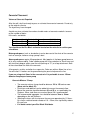
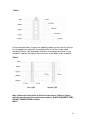
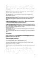
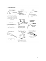
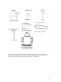
Installation Manual August 2009
Index
About this Manual............................................................................ 2
About Eco-Block............................................................................... 3
Getting Started.................................................................................. 7
Estimating Quantities........................................................................ 7
Labour Guidelines............................................................................. 8
Installation Guidelines...................................................................... 10
Installing the Bracing System.......................................................... 12
Installing Formwork for Windows and Doors..................................
12
Wall Insert Attachments .................................................................. 14
Pre Placement Checklist.................................................................
16
Concrete Placement......................................................................... 17
T Walls.............................................................................................. 22
Curved Walls..................................................................................... 24
Attaching Frame Walls...................................................................... 27
Interior & Exterior Finishes................................................................ 26
Water Proofing.................................................................................. 28
Electrical Cables & Plumbing............................................................. 29
Tools Required................................................................................. 34
1
Eco Block Aust Pty Ltd
Issued August 2009
Insulating Concrete Forms
Reducing Green House Emissions &
Saving Australia’s Energy
Phone: 1800-669-696
www.eco-blockaustralia.com.au
ABOUT THIS MANUAL
This manual is intended to assist the contractor or installer of the ECO-Block Insulating
Concrete Forming System in the proper techniques of construction
This manual assumes that generally accepted construction practices (i.e. level, plumb
and square) have been employed when building with the ECO-Block Insulating
Concrete Forming System. Structures built with the ECO-Block Insulating Concrete
Forming System should be designed, engineered, and constructed in accordance with
all applicable building codes and regulations.
DISCLAIMER
In keeping with ECO-Block Pty Ltd (Eco-Block) policy of continuing research and
development, we reserve the right to change or modify the contents of this manual at
any time. It is the responsibility of the end user to obtain the most recent information
available. Since ECO-Block has no control over installation or workmanship, no
responsibility for results is expressed or implied. ECO-Block Insulating Concrete Form
System and any other marks, drawings, or symbols are the trademarks of ECO-Block.
2
ABOUT ECO-BLOCK
ECO-Block is a highly versatile, cost efficient, easy-to-use, flat wall, insulating concrete
form (ICF) system. The unique patented design consists of foam panels, embedded
plastic webs every 203mm on centre and connectors. The system ships flat to save
space and freight cost. Workers at the job site quickly snap the plastic connectors onto
the web to create complete forms, ready for stacking.
Connectors are available in different lengths to create concrete walls 100mm (4 inch),
152mm (6 inch), 203mm (8"), or 250mm (10") thick using the same foam pieces.
Additionally, by using the ECO-Block plastic connector splice, two connectors can be
joined together to create walls of greater thickness.
Special right-angle forms are also available for making right and left hand corners.
These corner forms speed construction and provide an exterior corner-nailing strip.
ECO-Block has various locations to attach the connectors allowing the blocks to be cut
almost anywhere vertically horizontally, or at an angle and maintain a strong and stable
form.
ECO-Block is the most versatile, cost-effective method to get the benefits of flat wall,
insulating solid concrete construction:
Quality - a solid stable structure
Comfort - Indoor quiet FSTC 57 (152mm wall)
Safety - Disaster Resistance
Security - Increased resistance to natural disasters
Energy Efficiency - R-3.78 the one product for all climate zone
Green - No ozone depleting gas.
Due to Eco Blocks high insulating properties there is a 30 to 40% reduction the use of
cooling / heating needs therefore reducing green house emissions.
For further help and information, contact your local ECO-Block distributor or
ECO-Block 1-800-669-696.
3
Product Specifications
ECO-Block 2000 - Dimensions and Characteristics
101mm
152mm
203mm
Cavity Block Cavity Block Cavity Block
Block Dimensions
(Standard Block)
Concrete thickness
Concrete volume per
Block
EPS Thickness (total)
Wall Surface area per
Block
Fire Rating
Sound insulation
Thermal Insulation
90 deg corner
Block dimensions
1219 x 406 x
229mm
101mm
0.05 cubic m
1219 x 406 x
279mm
152mm
0.07 cubic m
1219 x 406 x
330mm
203mm
0.1 cubic m
127mm
0.5 sqm
127mm
0.5 sqm
127mm
0.5sqm
2 hours
42 db
R-3.78
0.26
Long side
813mm
Short side
406mm
4 hours +
51 db
R-3.78
0.26
Long side
813mm
Short side
406mm
4 hours +
51+ db
R-3.78
0.26
Long side
813mm
Short side
406mm
Straight forms connected together
Eco Block comes in left and right corners
4
5
Forming System Components
6
Getting Started
DESIGN
Before you can build a house, unit development, town house, commercial property or
renovate a property, it is important that you have approved building plans and permits.
If you have completed building plans and designs, the Architect or the Building Designer
may have already determined the external wall system for the building. The walls may
have been drawn to incorporate brick & timber, timber or block work. If you decide that
you want to use Eco Block then you may need to have your plans altered to
accommodate the Eco Block wall system.
Eco Block Aust Pty Ltd will provide you and your Architect or Building Designer with all
the technical material necessary.
ESTIMATING QUANTATIES OF ECO BLOCK
Number of courses required = Total wall height in millimetres DIVIDED by your form
height (.406mm)
Number of corner forms required = Number of course MULTIPLIED by the number
of corners on the building.
Straight forms required = ADD up the outside perimeter of the building and DIVIDE
by 4 then SUBTRACT the number of building corners. The remaining number is the
total number of straight forms required for one course.
Total number of straight blocks, including openings = straight forms per course
MULTIPLIED by the number of courses.
Add Corner blocks and straight blocks for the total number of forms.
Calculate the square meter of window and doors.
Subtract the forms saved at openings from the total number of forms for a solid wall.
Add 1-3% for waste (the lower percentage if you're more experienced). Minimal waste is
accomplished by placing cut pieces larger than 1 web and 2 foam bars back into the
wall.
7
Connector’s
Take the total number of Standard forms and multiply by the number of connectors per
block according to the system you are using (see chart below). In order to increase the
concrete holding capacity of the bottom course of forms, extra connectors can be
added. If you choose to add the extra connectors, you will need to take the perimeter
length/4 and multiply by 6 (6 extra connectors per block)
Take the number of corner forms and multiply by the number of connectors per block
according to the system you are using (see chart below)
Add these together for a total connector count.
System
Standard
Standard
Form Type
Corner
Standard
Connectors per Block
12
18
Example:
Connectors:
Straight forms = 231 x 18 = 4,158
Corner forms = 44 x 12 = 528
Concrete Estimation
Take the total number of forms (not including waste) and divide by the number of blocks
filled per cubic yard according to system type and core size.
One cubic meter of concrete will fill:
Table Below
System
Core Size
Standard
Standard
Standard
Standard
101mm
152mm
203mm
253mm
Num Blocks
Filled / m2
20
14
10
9.5
Your distributor will assist you with your calculations if required or use the calculator on
the Eco Block Web site.
Note:
An estimating program is available on the ECO-Block web site at
www.eco-blockaustralia.com.au, which will take all the guess work out of your
calculations.
8
LABOR GUIDELINES
Too achieve optimum results when building an ECO-Block structure, the ideal crew
would consist of:
· One experienced person (who understands level, plumb and square)
· Two labourers
The question is frequently asked-"how much labour is required to install ECO-Block
ICFs?" After carefully monitoring many past projects, the following guidelines have been
developed. These labour rate guidelines assume that the footings or concrete slab are
in place and ready to accept the first course of forms. These rates also assume a
standard height of 2.4m. The labour rates include erecting the forms, erecting and
stripping the alignment system, placing re-bar and concrete, and cleaning the site.
Below Grade Walls: (basements etc) Guidelines vary from .05 to .07 manhrs per .0929 square meter of wall
In other words, if a person was being paid $20.00/hr and was experienced, the labour
cost would be .05 man-hrs / square meter of wall x 20 / hr = $1.07 per .0929 square
meter of wall.
Above Grade Walls: Guidelines vary from .07 too .09 man-hrs per .0929
square meter of wall
These guidelines are higher due to the fact that there is usually more window and door
openings as well as more climbing require. Applying the above guidelines at a pay rate
of $20/hr @ .07 man-hrs / square meter of wall would equal $1.30 to $1.40 per .0929
square meter of wall.
These labour rates are offered only as guidelines, and may vary depending on the complexity of
the project and experience of the installer
A typical crew of three with boom pump operator
9
Installation Guidelines
Please note that these are guidelines. If you have any concerns regarding your
particular building you should seek clarification from your Eco Block Distributor.
Footings and Slab Guidelines
Footings and slab must be designed by your engineer so it is important that you follow
the Engineers plans and steel placement.
Pick a concrete firm for the footings and slab that are good enough to make it level
(within .3mm to .4mm). This is very important when the first course of block is laid. A
level footing or slab will eliminate the requirements to shim or shave block to achieve a
level wall.
Note: Formed footings are more accurate
Preparation and First Course
•
•
•
•
•
•
Use a chalk string line to mark where you will place the inside wall
Tip: While you are measuring your set outs, your crew should be
assembling the block and place them on their sides ready for
immediate use.
Note that the bottom course of block should have three connectors per
web while every course there after requires a minimum two
connectors
Ensure that the walls are square
Mark all of the door and window openings on the slab. Ensure that you label
the openings so that they are not easily rubbed off. This will serve as a
reminder of where to cut your forms as you build
Place the 65mm width length of ‘C” channel along the line. (Refer photo)
note that this will ensure that the Block does not move from its correct
position. Use a small concrete tack / nail to secure the “C” channel to the
concrete slab. These can be purchase from hardware stores.
Photo “C” Channel placement
10
With the “C” Channel” fixed to the slab or footing and with all the doors and
windows marked you are ready to place your first course.
•
•
•
•
Select a corner to start placing the forms. Place a corner form (right hand or
left) at the selected corner and begin to install the first course
Work in one direction around the foundation cutting the forms as necessary.
Use nylon zip ties to tie the top connector of each adjacent block together.
This will help to align the first course and create an excellent base for
subsequent courses
(Refer photo below)
Once the bottom course is completed you can start the second course.
•
•
•
With the second course work around the perimeter in the same fashion as
the first course if you have placed a right hand corner on the first course you
must place a left hand corner to start the second course. This will offset the
joints at 400mm on centre (refer to DVD to view an example)
If a cut leaves more than 8 bars past a web, attach a wooden strap across
the cut on each side of the form to reinforce the cut. Fix the wooden strap by
screwing it to the webs.
When you reach the sill level for the windows, notch/mark the forms to
indicate the width of the opening. This will remind you of the location of each
window. You then know where the blocks for the next course should be cut
to accommodate the window.
11
Placement of rebar
•
•
You must place your horizontal rebar as you build each course and in
accordance with the Engineers specifications
The rebar is staggered as you move up the wall and clips in to the
connectors
Photo: Example of Rebar Placement
•
•
•
Vertical rebar should be placed from the top of the wall and tied off against
either the connector or the horizontal rebar.
Thread the vertical rebar between the staggered horizontal bars making
sure there is one vertical bar next to each starter rebar coming out of the
foundation. Tie each vertical to the horizontal along the top or to a connector
to hold it firmly in the centre of the wall.
If you are building a single story home of ECO-Block, make sure the vertical
rebar is 8mm below the top of the wall or bottom of the sill plate. If another
story of ECO-Block will be built on top, make sure to leave enough rebar
extending, normally .600mm or as specified by the engineer beyond the top
of the wall to maintain the minimum lap requirements.
If another story of Eco Block will be built on top, make sure to leave enough rebar
extending, normally .600mm or as specified by the Engineer beyond the top of the
wall to maintain the minimum lap requirements.
Refer to the installation DVD which will show further details.
Use caution when tightening the ECO TIES. It is possible to pull the outer panel of the
"top" leg wall in too far.
Properly tightened, there should be no more than .3mm of inward deflection of the
connectors.
12
Technical Tip:
Keep vertical bar 8mm from the top of wall. Remember to maintain your minimum rebar
overlap requirements as per your engineering drawings.
Installing the Bracing System
•
•
•
•
•
•
•
•
•
•
When you have completed your third or fourth course of Eco Block, it is time
to stand and attach the bracing system to the Eco Block wall
Braces are to be spaced .500mm off the corner and at 1.2m to 1.8m
intervals. The intervals are determined by the size of the concrete cavity. For
example for 101mm concrete cavity the bracing may be at 1.8m whilst for
152mm cavity the braces may be placed at 1.5m intervals.
Place the strong back precisely on the chalk line that was previously
snapped on the footing/slab
The strong back must be aligned with the plastic web
Use a 15 mm screw with wide head to screw the strong back to the web
When screwing the strong back into the webs, make sure to place the
screws in the top of the slots, snug them, but do not over tighten. This will
allow the forms to “settle” slightly as the concrete is placed.
When the wall is plumb, attach the foot of the strong back to the slab or
footing with concrete tap cons they are 5 to 6mm gauge and 35 to 45mm in
length.
Place the seat of the brace on the strong back
Now secure the diagonal turnbuckle to the slab or soil making sure the
turnbuckle is in the middle position so it can be adjusted in either direction.
Once again use 5 to 6mm gauge hex head screw as above. Refer photo
below.
Note: If the walk boards are 2.4m or more above the ground, you must
install the hand rails and toe boards. We recommend that you use the
hand rail at all times. This may vary from State to State. We
recommend that you find out what the health safety requirements are
for your region to be sure.
Photo of Strong back & platform
13
Installation of formwork for windows and doors
1. Formwork for all the doors and windows can be installed,
As you install the wall or
When you have finished installing the wall
2. There are various options available with respect to setting formwork around
the windows and doors. You may choose either of the following,
18mm timber form work
Polystyrene formwork
Powder coated pressed steel form work
(Photo Steel powder coated windows)
(Photo of timber formwork)
14
Wall inserts and other pre-placement attachments
Put sleeves for penetrations and anchors for interior walls into the formwork before
the pour.
Put a sleeve for anything that will have to pass through the wall, such as:
Water, electric, phone, CATV and gas service
Sewer connection
Wire for outdoor lights and doorbells
Use a length of PVC pipe longer than the width of the wall for easy placement.
The diameter of the PVC pipe should be slightly larger than what will be placed
through it
Use expanding foam to seal around the pipe
After the pour is complete and the bracing system is removed, trim the excess PVC
flush with the forms.
Technical Tip:
Make a comprehensive list of penetrations and add to a pre-pour checklist. When
you have finished assembling the Eco Block wall and the formwork and before you
place the concrete it is important that you;
Plumb the wall
Plumb and straighten all walls before the pour. By attaching scrap 50mm x 90mm
in the corners vertically on the top course of forms you will be able to run a string
line around the building. As one worker measures along the wall to make sure the
distance between the string and the wall is consistent, someone else can be
adjusting the kickers as necessary to bring the wall into plumb.
Technical Tip:
Check to make certain that the diagonal turnbuckles of the wall alignment system
are adjusted to the middle of their travel.
Covering the top of wall
If another story of ECO-Block will be built on top of this one, cover all the top edges
of the wall with wide tape or something else removable. This keeps the top of the
forms clean, which allows additional forms to be stacked on top.
Technical Tip:
1.2m-1.8m pieces of plastic or aluminium gutter work well to cover the top of the
wall. These pieces may be moved along as you pour. Wide tape will also work well
to cover the top of the block.
Use the Pre Placement checklist on the next page to ensure that you are
ready for the next phase, placement of concrete.
15
Pre Placement checklist
Item
Done
Does the layout match the plans everywhere?
Is the walls plumb everywhere?
Are the walls square?
Is the top of the wall level?
Is each window/door formwork in place, level, plumb and square?
Is each window/door formwork connected to the forms?
Are all window/door formwork diagonally braced against racking?
Are all cuts and potential weak spots reinforced?
Are all penetration sleeves in place and glued securely?
Are all anchor bolts for interior walls in place?
Are all vertical bars in position and tied securely?
Are all beam pockets installed?
Are all lintels properly reinforced?
Is the ledger or ledger connections (if any) in place and securely fastened?
Have you planned out the position of the anchor bolts or straps (if any) at the top of the wall?
Do you have enough anchor bolts or straps on hand for the top of the wall?
Do you have squares of plywood or scrap 1 x 4s to screw over the wall if weak spots appear?
Have you received your building department inspection approval?
Have you received your engineer inspection and approval?
Is the job site clear for the operation of the concrete truck, pump (if any) and the crew that will be on
the ground?
Is the concrete ordered and quantity verified?
Is the pump (if any) ordered?
Is the site clear?
Is there good access for the pump truck and concrete truck?
16
Concrete Placement
Volume of Concrete Required
After the wall is built and ready to pour, re-estimate the amount of concrete. Do not rely
on the original estimate.
The layout may have changed.
A quick way to re-estimate the number of cubic meters of concrete needed is to count
up the number of blocks
in the walls, and divide:
For 101mm (4”) wall Divide by 20 One cubic meter fills 20 blocks
For 152mm (6”) wall Divide by 14 One cubic meter fills 14 blocks
For 203mm (8”) wall Divide by 10 One cubic meter fills 10 blocks
You should use the Eco Block estimator located on the web site to confirm your
calculations
Below-grade pours (such as foundations) can be done out of the chute of the concrete
truck or conveyer, however using a pump is best.
Above-grade pours require lifting equipment. Most popular is the boom pump because
of its easy manoeuvrability. Order a boom pump with a line reduction to 75mm hose and
with two ninety-degree angles near the end (forming an "S") or a loop attachment. Both
of these slow down the flow of the concrete.
A line pump is smaller, and often less expensive. Order one with an 80mm line or less.
You will need 1-2 workers on the ground during the pour to help move the line.
If you are using steel fibres in the concrete mix it is preferable to use a 100mm
diameter line pump or boom pump
Concrete Mixture / Slump
•
•
•
•
•
•
The concrete mixture slump should be between 120 to 150 and no more.
(Never ask for block fill)
Plasticizers and additives can be added to increase the concrete flow
Mpa of the concrete should be between 20 and 25 or, as specified by the
Engineer. When steel fibres are used an Mpa of 20 is recommended
The recommended aggregate size should be between 7mm to 10mm
depending on the wall thickness
Vibrating the forms will also increase the pressure approximately 1.5 times.
By using a smaller diameter vibrator of 18 – 25mm, can significantly reduce
this pressure
If in doubt contact your Eco Block Distributor
17
If, the engineer or architect on the job specifies another mix design, follow their
specifications.
Photo: Concrete pour with a boom pump.
During the pour, concrete puts outward pressure (refer to tables 1 & 2)on the
forms. ECO-Block is designed to withstand it. However, the installer needs to avoid
steps that would dangerously increase these pressures.
Things that increase the outward pressure on the forms are:
· The force of the falling concrete
· Vibration
· Water added to the concrete
As concrete falls into the forms it exerts an outward pressure approximately 1.5
times greater than the pressure it exerts when it is resting in the forms. Many
recommendations are geared towards minimizing this extra pressure, including
using an S-bend on a boom pump, a 80mm line on any pump, and breaking the fall
of the concrete from the chute with a shovel. Not doing these things will increase
the pressure on the forms and the risk of form failure. The maximum pressure
develops at the bottom of the lift.
Adding extra water to the concrete can increase pressures more than 1.5 times
depending on the amount added. It also weakens the final concrete, and may
weaken it below what is required. Therefore ADDING EXTRA WATER TO THE
CONCRETE IS NOT RECOMMENDED.
18
. Table 1
As the concrete hardens, the pressure gradually reduces to near zero. By the time
the crew begins the second lift, the concrete of the first lift has usually cured
enough that there is little likelihood of difficulties in the bottom of the wall. As the
second lift is poured, the highest pressure occurs at the bottom of the second lift.
Table 2
Note: 101mm wall cavity tends to fill much faster than a 152mm or thicker
wall, the concrete pressures tend to occur quicker. PLACE CONCRETE VERY
SLOWLY WHEN FILLING A 101mm
WALL!
19
Plan to get experienced help the first couple of times you place the concrete.
Select a starting point near the centre of a wall. Begin placing concrete in the wall,
swinging the concrete hose in a back and forth motion, while moving around the
wall perimeter.
Each pass around the wall perimeter is considered a "lift". Concrete should be
placed in 1.5m lifts until the wall cavity is filled.
The swinging motion of the hose allows the concrete pressure to be evenly
dispersed over several feet.
When pouring a corner swing the hose to either side of the corner allowing the
concrete pressure to be dispersed away from the corner, NOT directly in the
corner.
Follow the same procedure on the remaining walls, working around the building
in a consistent direction (clockwise or counter clockwise).
Follow the same procedure outlined above as many times as necessary until the
wall is filled keeping in mind that if another story of ECO-Block will be built on top of
this one, the concrete should be kept at least 100mm
below the top of the wall.
Technical Tip: While the walls are being poured, protect the top of the block with
tape (masking, duct, etc.).
This will keep the tongue connection clean allowing for easy stacking of additional
forms.
Very Important
Have 1-2 workers on the ground continuously consolidating the concrete and
watching for bulges, should they occur.
Some consolidation methods are:
Use an internal vibrator 18mm / 20mm in diameter or less.
Remember to consolidate from the bottom of the wall towards the top, and be
careful not the hit the sides of the form.
“Roding" plunge a length of rebar up and down a few times into the concrete from
above.
Touch the vertical rebar with a reciprocating saw after the blade has been
removed.
Use a hammer and a block of timber. Place the timber against the wall / web and
tap it mildly with a hammer.
20
Consolidate every 203 to 400mm or so repeatedly down each wall, following the
pour.
If the crew spots a bulge, reinforce it with a square of plywood screwed flat over
the bulge. Screw these wood reinforcements directly to the ECO-Block webs with
#10 course thread drywall screws.
Bulge in wall
Repaired with plywood
Technical Tip:
Protect the top of the wall from damage with aluminium or plastic gutter pieces or
tape.
If any of the foam happens to blow out, stop the concrete placement on that wall.
This rarely happens but it is
possible if the rate of placement has been too fast, or the concrete is too wet, or
the connectors have not been installed correctly.
Move the placement to the next wall and continue to work as the crew repairs the
hole.
To repair the hole, remove the concrete down to the bottom of the hole.
Replace the torn form fragment, cover it by screwing plywood or 100 x 25mm to
the webs at least 41mm, or (2) webs beyond the torn form.
The placement can now resume on the repaired wall.
If you are building another story of ECO-Block on top of this one;
Leave the concrete rough on top and at least 100mm below the top of the wall.
If a roof or frame walls will go on top, trowel the concrete smooth and check the
wall for level at close intervals.
Insert anchor bolts or straps as necessary for the roof trusses or top plate.
21
Before, during and after placement, check the string line and adjust the braces as
necessary to bring the wall to perfect plumb everywhere. Immediately after the
pour, check all dimensions, including diagonals and adjust as necessary.
One day after the concrete has set the reinforcement / form work around the
windows and doors can be removed.
Do not remove the bracing and scaffolding until the concrete has reached
adequate strength, usually 3-5 days.
Technical Tip:
When creating a wall greater than 300mm in thickness, please contact your
Distributor or the ECO-Block office for specific instructions.
Formwork stripped away the following day
T-Walls
With the ECO Block System, T-wall intersections are easily and quickly
accomplished. A "T" wall occurs when one wall has a second wall adjoin it in the
middle of its run.
To build a T-wall, place the first block of the wall that forms the leg of the "T"
against the wall forming the top of the "T". Mark the panel of the top of the "T",
indicating where the concrete core of the leg wall will be. This is the section that
needs to be cut and removed.
Should the concrete core of the leg wall occur where a web is positioned in the top
wall, cut and remove this section of panel including the web. This situation is why
we have the Tie Anchor to tie the outside of the removed web to the webs in the
leg of the "T".
22
Assembly
If the leg wall core occurs between the webs of the top wall, simply butt the forms
together and use Zip ties around the connectors of both walls to pull the walls
together.
If the leg wall core occurs where a web has been removed, use (2)-Tie Anchors
attached to the second and fourth positions of the remaining web in the top wall.
Use (2)-900mm Zip Ties to pull the walls together by
slipping a zip tie through each of the Tie Anchors and around the connectors of the
leg wall.
Place rebar as specified.
Example of T wall assembly
Refer to installation video for more examples
23
CURVED WALL
.
24
25
26
ATTACHING FRAME WALLS
Attaching interior frame walls to the exterior ECO-Block walls can be accomplished
in a number of ways.
Method 1:
Prior to concrete placement, locate the interior walls. Insert the proper anchors
through the foam and into the concrete core. Upon concrete placement, the
anchors will be embedded into the concrete core.
Method 2:
If the interior walls happen to fall on one of the webs that are located every 203mm
on centre, simply screw the stud to the web with a coarse thread drywall screw.
Method 3:
Locate the interior wall partition and remove the section of foam. By removing the
foam, the treated stud can now be anchored directly to the concrete core with the
proper mounting hardware.
27
Waterproofing- Below grade
There are many different waterproofing products available. These range from self-adhesive membranes too
spray on and roll-on products so long as they are foam compatible. Products with solvents in them can
dissolve the foam so always check with the manufacturer or distributor of the water proofing product
concerning application to EPS, prior to the application.
Waterproofing products such as the following,
Note that Eco Block does not represent the companies.
PARGING
MANUFACTURER
PRODUCT
TYPE
APPLICATION
TREMCO
RYDALMERE NSW
TREMCO
RYDALMERE NSW
TREMPROOF
3000
PARASEAL LG
HAND
TREMCO
RYDALMERE NSW
SALTWATER
PARASEAL
PASCO
RICHMOND VICTORIA
CHEMIND
CONSTRUCTION
PRODUCTS
AQUAPROOF
301BL
NEWFLEX
WAM FIBRE
SELF ADHESIVE EXTRUDED
SHEET
MULTI COMPONENT
GRANULAR SHEET
MEMBRANE
ELASTOMERIC SHEET
MEMBRANE SPECIFICALLY
DESIGNED FOR AREAS
SUBJECTED TO SALINE,
ALKALINE, ACID ETC
ACRYLIC BASED LAYTEX
BITUMUN COATING
POLYURETHANE MODIFIED
SYNTHETIC RUBBER
POLYMER
HAND
HAND
HAND ROLL ON
BRUSH OR
ROLLER
Please note that Eco Block recommends that for below ground basements /
car parks the exterior face of Eco Block must always be water proofed /
tanked in accordance with the BCA, Engineers and Architects / Designers
details.
If you wish to add a water proofing additive to the concrete, then Eco Block
makes no claims that the additive will in any way improve the waterproofing
performance of Eco Block or the concrete performance. You should seek
independent advice with respect to any concrete additive and the claims of
the manufacturer.
28
Electrical and plumbing lines are easily installed into the ECO-Block wall. For
electrical boxes, use a hot knife or router to remove the foam at the desired
location. Once the foam is removed the boxes can be screwed to the webs using a
standard drywall screw, screwed to the concrete using concrete anchors, or glued
to the concrete.
Example of plumbing installation
Example of electrical installation & plumbing
To create channels in the foam for wiring, use a hot knife, router, or electric chain
saw with a depth stop or jig saw. Angle the channel so it has a lip on the bottom to
hold the cable in place, or spot glue the cable with EPS compatible foam adhesive.
The channels for the plumbing lines will be created in the same fashion. For larger
lines furring out the wall may be necessary.
Plumbing can be installed inside the wall cavity prior to the pour, but this can create
a severe weak spot, so be sure to check with an engineer first.
Technical Tip:
Cut horizontal runs at the course-to-course interlock, since webs are cut short at
this point.
29
Interior
Workers can screw plaster board and other forms of panelling to the plastic webs
just as it attaches over frame construction. You can use a foam-compatible
adhesive in addition to or instead of screws if you prefer. Check with your local
building code if you choose to use only foam - compatible adhesive.
Eco-Block recommends using screws, however if you choose to nail, use
ring-shank nails for a better grip.
Example of fixing plasterboard
Eco Block
For very heavy wall-mounted fixtures (like a sink), rout out or hot knife the foam to
make room for timber that you attach directly to the concrete with concrete screws.
Later you can screw the fixture to the wood. When installing cabinets, it is a good
idea to screw plywood, sized slightly smaller than the
outline of the cabinets to the ECO, this provides and excellent surface for
fastening the cabinets. Butt the wallboard directly up to the edge of the plywood.
Exterior
Any nailed or screwed siding (plastic, vinyl, timber and cement sheets) attaches to
the ECO-Block webs. Eco-Block recommends screwing with #10 course thread
screws, however, if you choose to nail, use ring-shank nails for a better grip.
Consult the manufacturer of the siding for specific installation instructions. ECOBlock can accommodate either a cement render or an acrylic-based product. Both
types are typically reinforced with fibreglass mesh. They are
durable and resist cracking in both hot and cold climates. For the proper installation
requirements, consult the manufacturer of the stucco product you choose.
Below grade, use water proofing just as you would over a conventional
basement. (Refer to our design consideration manual)
30
Self-adhesive membranes work well as do spray-on and roll-on products so long
as they are foam-compatible. (Refer to our design consideration manual)
Very Important
Products with solvents in them can dissolve the foam, so check with the
manufacturer or distributor of the
waterproofing product concerning application to EPS, prior to application.
Please refer to the installation video for more examples.
Additional Professional Design Details are available from ECO-Block Australia Pty
Ltd. Please contact your local Distributor or Eco-Block 1800-669-696.
This manual is a guide, if you are unsure on how to complete any part of the
installation process contact your Distributor who will assist you.
Eco Block Basement with braces erected, hand rails
31
32
33