1
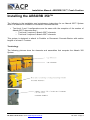
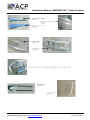
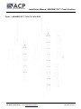
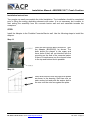
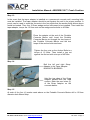
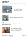
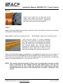
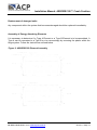
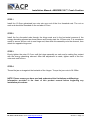
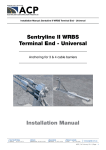
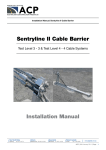
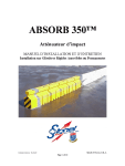
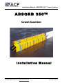
Installation Manual: ABSORB 350™ Crash Cushion
ABSORB 350™
Crash Cushion
Installation Manual
Ph 0061 2 9772 4172 or visit www.acprod.com.au
Jan 2011 / Page 1
Installation Manual: ABSORB 350™ Crash Cushion
ABSORB 350™ Crash Cushion Product
Specifications
Product Specification: ABSORB 350™ TL-2
Non Re-directive, Gating, Crash Cushion Applied to Permanent or Portable Concrete Barrier
I. General
The ABSORB 350™ TL-2 System is a Non Re-directive, Gating, Crash Cushion in accordance
with the definitions in the National Cooperative Highway Research Program Report 350
(NCHRP 350). The system shall be tested and perform in an acceptable manner in
accordance with the guidelines of NCHRP 350 at Test Level-2 (70kph).
II. Performance
The ABSORB 350™ is designed to absorb the impact energy of an errant vehicle in
accordance with NCHRP 350 guidelines for Non Re-directive, Gating, Crash Cushions. The
system is designed to attach to Permanent or Portable Concrete Barrier (PCB) with section
lengths of at least 3.1 metres. When attached in accordance with the manufacturers
instructions, the ABSORB 350 system is capable of safely stopping a 2000kg pickup truck
impacting the system at 70kph and 0 degrees and an 820kg compact vehicle impacting the
system at 70 km/h, 0 degrees and with an offset of the vehicle and system centrelines of onefourth the vehicle width.
A.
When properly installed according to the manufacturer's recommendations the
ABSORB 350™ system shall be fully tested to and meet the recommended structural
adequacy, occupant risk, and vehicle trajectory criteria set forth in NCHRP 350 for Test Level
2 Non Re-directive, Gating, Crash Cushions (NCHRP 350 TL-2): Impact at 0 degrees at w/4
offset (centreline of vehicle offset 1/4 width of vehicle from centreline of system) at 70kph with
an
820kg
vehicle.
This
is
Ph 0061 2 9772 4172 or visit www.acprod.com.au
Test
2-40
of
NCHRP
350.
Jan 2011 / Page 2
Installation Manual: ABSORB 350™ Crash Cushion
Installing the ABSORB 350™
The following is the installation and maintenance instructions for an Absorb 350™ System
when it is attached to Portable or Permanent Concrete Barriers.
•
Test level 2 and 3 configurations are the same with the exception of the number of
Absorb 350™ elements used…
o Test level 2 requires 5 Absorb 350™ elements
o Test level 3 requires 9 Absorb 350™ elements
This system is designed to attach to Portable or Permanent Concrete Barrier with section
lengths of at least 3.1 metres.
Terminology
The following pictures show the elements and assemblies that comprise the Absorb 350
System.
Ph 0061 2 9772 4172 or visit www.acprod.com.au
Jan 2011 / Page 3
Installation Manual: ABSORB 350™ Crash Cushion
Ph 0061 2 9772 4172 or visit www.acprod.com.au
Jan 2011 / Page 4
Installation Manual: ABSORB 350™ Crash Cushion
Figure 1: ABSORB 350™ TL2 & TL3 with PCB
Ph 0061 2 9772 4172 or visit www.acprod.com.au
Jan 2011 / Page 5
Installation Manual: ABSORB 350™ Crash Cushion
Installation Instructions
Two people can easily accomplish the initial installation. The installation should be completed
prior to filling the energy absorbing elements with water. It is not necessary but is easier to
start setting the assembly from the concrete barrier wall end and assemble towards the
nosepiece.
STEP l
Install the Adapter to the Portable Concrete Barrier wall. Use the following steps to install the
Adaptor.
Step 1.1
Place the two Anchor Bolts (AOOO521 ) into
the Adapter (BOOO520) as shown. The
bolts should be placed in the upper and
lower holes if they will not interfere with the
mounting on the end of the concrete barrier
If there is interference use the closest holes
to the top and bottom that is possible.
Step 1.2
Place both anchor bolts through both plates
as shown in the drawing. Start two nuts on
each anchor bolt and push the anchor bolt to
the rear until the nuts are against the plate.
Ph 0061 2 9772 4172 or visit www.acprod.com.au
Jan 2011 / Page 6
Installation Manual: ABSORB 350™ Crash Cushion
Step 1.3
In the event that the taper adapter is installed on a permanent concrete wall, mounting bolts
must be installed. The taper adapter should be set against the wall in its proper position. A
punch can be used to mark the concrete in the four spots that the anchor bolts shown above
would be located. Then four 12.5mm wedge anchor bolts need to be installed. Then install the
taper adapter, torque the 12.5mm nuts on the wedge anchor bolts to 40 ft/lbs.
Place the adapter at the end of the Portable
Concrete Barrier wall. Insert the Portable
Concrete Barrier pin through the two loops of
the Portable Concrete Barrier and the two
loops of the anchor bolts as shown.
Tighten the four nuts on the Anchor Bolts to a
torque of 15 ft/lbs. Then install a jam nut
against the first nut with a torque of 40 ft/lbs.
Step 1.4
Bolt the left and right Strap
Adapter to the Taper Adapter.
BOO0207 & BOO0209
Hold the top edge of the Strap
Adaptor parallel with the road
surface. Mark the rear holes (2)
of the Strap Adaptor on the
concrete barrier.
Step 1.5
At each of the four (4) marks made above on the Portable Concrete Barrier drill a 12.5mm
diameter hole 94mm deep.
Ph 0061 2 9772 4172 or visit www.acprod.com.au
Jan 2011 / Page 7
Installation Manual: ABSORB 350™ Crash Cushion
Step 1.6
Install four (4) 12.5 x 106mm
(wedge anchor) cement anchor
bolts. Place one 12.5mm flat
washer and nut on each anchor
bolt. Torque the nuts to 40 ft/lbs.
Step 1.7
Install the Hinge Plate Adapter (BOOO611) onto the
Taper Adapter as shown with eight (8) 12.5mm X
32mm NC GR 5 CADII PLTD bolts
STEP 2
Install the first Energy Absorbing Element (Type "A") to the Hinge Plate Adapter. For element
assembly see pages C-10 and C-11.
Step 2.1
Install the centre pivot bolt, 12.5mm X
200mm and 12.5mm nylock nut. Tighten the
nut only until the end of the bolt threads
protrude out of the nylon portion of the nut.
Ph 0061 2 9772 4172 or visit www.acprod.com.au
Jan 2011 / Page 8
Installation Manual: ABSORB 350™ Crash Cushion
Step 2.2
Install a Link Hinge Pin on each side of the
hinge. Then make sure that the clip that is
attached to the end of the chain is installed into
the hole in the end of the Link Hinge Pin.
STEP 3
Install the Energy Absorbing Elements. Install the Centre Pivot Bolt and the two Link-Hinge
Locking Pins on each element.
Test Level 2 - install five (5) elements total
Test Level 3 - install nine (9) elements total.
There are two types of Energy Absorbing
Elements. Each type has a forward and rearward
end. The forward end is considered the end that
faces the Nose Piece. The rearward end faces
the Concrete Barrier wall. The two types of
elements are identified by the number of vertical
indentations along each side in relation to the
front and rear hinges. See elements on page C-1.
When the Absorb 350 system is assembled, it is important to ensure that the two types of
elements are ALWAYS ASSEMBLED IN AN ALTERNATING FASHION as shown in Figure 1.
Thus, when you look down either side of the assembled system, you should see an alternating
pattern of vertical indentations (i.e. two, one, two, one, etc.).
NOTE: The second and third elements of Test Level 3 systems must have two vent/fill
holes. If elements are not available with the two vent/fill holes in the top, the
second hole must be cut in these two elements. The whole layout and size
measurements are the same as the existing hole. See figure 1 drawing of Test
Level 3.
Ph 0061 2 9772 4172 or visit www.acprod.com.au
Jan 2011 / Page 9
Installation Manual: ABSORB 350™ Crash Cushion
STEP 4
Six tabs are loosely bolted (so they swivel for adjustment) onto the last hinge assembly before
the Nose Piece. These tabs are the mounting points for the nosepiece. Three of the tabs have
nuts welded onto one end. These go on the top of the bottom bar of the hinge assembly. The
three tabs with a hole in each end go on the bottom side of the top bar of the assembly as
shown below. (These tabs may already be installed.)
STEP 5
Install the nosepiece on the end of the last Type A element. There are three 12.5mm X 150mm
bolts that secure the nosepiece to the tabs on the hinge assembly. There are three access
holes in the nosepiece that allows installation of these bolts. These bolts must be securely
tightened. It is very important that the Nose Piece does not become detached during an
impact.
STEP 6
If necessary adjust the Energy Absorbing Elements so there is a straight alignment with the
downstream QMB system.
Ph 0061 2 9772 4172 or visit www.acprod.com.au
Jan 2011 / Page 10
Installation Manual: ABSORB 350™ Crash Cushion
STEP 7
Fill all of the Energy Absorbing Elements with water, except the first element. The plastic
container that attaches to the nosepiece is the only container that does not have any water.
The remaining containers are filled with water to a level that is within 50mm from the top of the
container.
Test Level 2: Fill 4 elements
Test Level 3: Fill 8 elements
NOTE: Filling the element attached to the nose piece with water will cause the system
to perform improperly and may cause serious bodily injury.
In regions where the water filled Absorb 350™ elements could become frozen, proper
antifreeze agents should be used. Care should be taken to ensure that proper antifreeze
agents are used in accordance with local regulations, environmental concerns and ensuring
that any post impact liquid on the road surface does not constitute an undue hazard to
adjacent motorists.
The Absorb 350™ elements should be inspected regularly to ensure that the elements that are
intended to contain water (or antifreeze fluid) are kept at adequate fill levels.
STEP 8
Install the evaporation prevention cap into the top of each plastic container.
The cap needs to be securely pushed down to
prevent evaporation. In addition the tie strap should
be securely fastened to the plastic element.
STEP 9
Installing delineation: Depending on local authority specifications, install delineation as
necessary to the front of the painted nosepiece.
Inspection:
The metal components and fasteners of the system should be periodically inspected to ensure
that the system remains intact and able to perform in a safe and effective manner.
Ph 0061 2 9772 4172 or visit www.acprod.com.au
Jan 2011 / Page 11
Installation Manual: ABSORB 350™ Crash Cushion
Replacement of damaged units:
Any component within the system that becomes damaged should be replaced immediately.
Assembly of Energy Absorbing Elements
It is necessary to determine if a Type A Element or a Type B Element is to be assembled. A
Type A can be converted to a Type B or vice versa simply by reversing the plastic within the
hinge system. Follow the instructions outlined below.
Figure 2: ABSORB 350 Element Assembly
Ph 0061 2 9772 4172 or visit www.acprod.com.au
Jan 2011 / Page 12
Installation Manual: ABSORB 350™ Crash Cushion
STEP 1
Install the 12.5mm galvanised jam nuts onto one end of the four threaded rods. The nut on
each end should be threaded on the rod about 37mm.
STEP 2
Install the four threaded rods through the hinge ends and in the horizontal grooves of the
energy absorbing element as shown above and loosely start the 12.5mm nuts. It is sometimes
easier to secure all four rods to one hinge end, then slide this assembly onto the element, then
attach the opposite hinge end.
STEP 3
Evenly tighten the outer 12.5 mm until the hinge assembly on each end is making firm contact
with the energy absorbing element. After this adjustment is made, tighten each of the four
outer nuts one full turn.
STEP 4
Thread the jam nuts against the backside of the hinges. Torque the jam nuts to 54.23Nm
NOTE: Please ensure you have read and understood the Limitations and Warnings
Information provided in the front of this product manual before beginning any
installation procedures.
Ph 0061 2 9772 4172 or visit www.acprod.com.au
Jan 2011 / Page 13