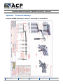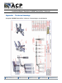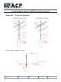
1
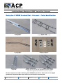
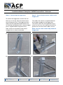
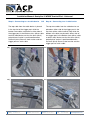
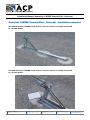
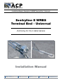
Installation Manual: Sentryline II WRBS Terminal End - Universal
Sentryline II WRBS
Terminal End - Universal
Anchoring for 3 & 4 cable barriers
Installation Manual
New South Wales
Sydney 02 9772 4172
Victoria
Melbourne 03 9213 5199
Queensland
Brisbane 07 3271 9133
Western Austalia
Perth
04 1743 0230
www.acprod.com.au
ACP | 7th February 2011 | Page
1
Installation Manual: Sentryline II WRBS Terminal End - Universal
Table of contents
Introduction
3
System statements
3
Before installation 4
Foundation piles
4
4
Tools required Parts identification 5
Bill of materials 6
7
Installation instructions Installation examples 12
13
Sentryline II WRBS Terminal End - Universal 4 cable barrier 14
Sentryline II WRBS Terminal End - Universal 3 cable barrier 15
Installation checklist Appendix – technical drawings
Sentryline II WRBS Terminal End - Universal 3 & 4 cable line post set up
16
Sentryline II WRBS Terminal End - Universal Batter hinge point set up
New South Wales
Sydney 02 9772 4172
Victoria
Melbourne 03 9213 5199
Queensland
Brisbane 07 3271 9133
16
Western Austalia
Perth
04 1743 0230
www.acprod.com.au
ACP | 7th February 2011 | Page
2
Installation Manual: Sentryline II WRBS Terminal End - Universal
Sentryline II WRBS Terminal End - Universal
Introduction
Safety statements
The Sentryline II WRBS Terminal End - Universal
is used to anchor a high tensioned 3 or 4 cable
barrier to the ground. The Sentryline II WRBS
Terminal End has been designed and tested to
meet the evaluation criteria of NCHRP 350.
The Sentryline II WRBS Terminal End - Universal
has been tested to the guidelines in NCHRP 350
for a gating, re-directive cable barrier terminal
end. When correctly installed, the Sentryline II
WRBS Terminal End - Universal allows a vehicle
to over ride or gate through the high tensioned
anchor area of the terminal end.
The unique Sentryline II WRBS Terminal End
- Universal technology is based on a series
of cables, special washers and a ‘trigger’
post. This setup offers exceptional vehicle
control when the cables are impacted as they
disconnect from the top of the trigger post and
the cable barrier is de-tensioned immediately,
thus eliminating any potential of the errant
vehicle to vault, roll or snag.
General safety
All required traffic safety precautions should
be complied with. All workers should wear
required safety clothing (high visibility vests,
steel capped footwear, gloves, hard hats, safety
glasses etc.).
Only authorised trained personnel should
operate any machinery. Where overhead
machinery is used, care must be taken to avoid
any overhead hazards. Before auguring, always have the area checked
for underground services by the appropriate
service providers.
Gloves should be worn at all times.
Sentryline II WRBS Terminal End - Universal
safety statements
All installers must be well clear of machinery
while the holes are augured. The components
are not heavy enough to require specialized
lifting equipment, but due to the dimensions
and bulky nature, care should be taken when
lifting the larger components into position. A
maximum weight of 38kg will be encountered
when installing the ground strut and rebar cage
assembly, two installers should do this.
Avoid placing hands or fingers in and around
moving parts when components are being lifted
and manoeuvred into place.
New South Wales
Sydney 02 9772 4172
Victoria
Melbourne 03 9213 5199
Queensland
Brisbane 07 3271 9133
Western Austalia
Perth
04 1743 0230
www.acprod.com.au
ACP | 7th February 2011 | Page
3
Installation Manual: Sentryline II WRBS Terminal End - Universal
Before installation
Foundation piles
Design, selection and placement of the
Sentryline II WRBS Terminal End - Universal shall be in accordance with the local road
authority guidelines and the details shown in
the construction drawings. Installation shall be
in accordance with the installation instructions
supplied for this product.
Two foundation options are available; the soil
conditions that exist on site will determine which
option to use.
Before installing a Sentryline II WRBS Terminal
End - Universal , ensure that all components
required for the terminal end are on site and
have been identified. The Sentryline II WRBS
Terminal End - Universal is a highly engineered
safety device made up of a relatively small
number of parts. Before starting installation
ensure that one is familiar with the make up of
the terminal end. Refer to the ‘Bill of materials’
and ‘Parts identification’ sections in this manual
for more information.
Depending on the application and
circumstances at the site, installation and
assembly of the system should take one person
crew less than 15mins once the concrete
foundation piles are poured and set.
NOTE: IF THE SOIL CONDITIONS ARE
UNKNOWN THE ‘DEFAULT’ OPTION MUST
BE USED AT ALL TIMES.
Default Option
The ground strut and rebar cage assembly must
be cast into piles with the following dimensions.
The augured holes for this option are 450mm
diameter by 2500mm deep and required to be
filled with 25mpa concrete. (Shown in figure A
below.)
Shallow Option
ONLY if the soil has been verified as a particular
soil using a DCP (dynamic cone penetrometer)
or SV (shear vane) with results that match or
exceed the required parameter can the ‘shallow’
pile option be used. The dimensions of these
holes are 450mm diameter by 1000mm deep
and required to be filled with 25mpa concrete.
Tools required
The same tools required to install the cable
barrier will also install an Sentryline II WRBS
Terminal End - Universal:
> Auger for drilling holes, 450mm and 300mm
> 300mm Wrench
> Measuring tape
> String line
> Cut off saw
New South Wales
Sydney 02 9772 4172
Victoria
Melbourne 03 9213 5199
Queensland
Brisbane 07 3271 9133
Western Austalia
Perth
04 1743 0230
www.acprod.com.au
ACP | 7th February 2011 | Page
4
Installation Manual: Sentryline II WRBS Terminal End - Universal
Sentryline II WRBS Terminal End - Universal - Parts identification
Rebar cage
Ground strut
(1 required) (3 required plus 12x M24 nuts) Anchor cables
Washers and nuts
(Full set shown) (2 required) Trigger post
(1 required) 3 Wire cable barrier
4 Wire cable barrier
(Fittings may vary; the 3mm thick polyethylene washers and 6mm
thick, 50mm ø galvanised steel washers are always required)
All steel components used in the Sentryline II WRBS Terminal End - Universal are hot dipped
galvanised, except the rebar cages which are cast into the concrete piles.
New South Wales
Sydney 02 9772 4172
Victoria
Melbourne 03 9213 5199
Queensland
Brisbane 07 3271 9133
Western Austalia
Perth
04 1743 0230
www.acprod.com.au
ACP | 7th February 2011 | Page
5
Installation Manual: Sentryline II WRBS Terminal End - Universal
Sentryline II WRBS Terminal End - Universal - Bill of materials
Sentryline II WRBS Terminal End - Universal
(connected to a 4 cable barrier)
> 1 x Ground strut
> 3 x Rebar cages (c/w 12x M24 nuts)
> 1 x Trigger post
> 2 x Anchor cables (c/w 4 x M24 nuts)
> 1 x 10mm thick rectangular steel washer
> 1 x 6mm thick rectangular steel washer
> 1 x 3mm thick rectangular polyethylene washer
> 4 x 3mm thick square polyethylene washers
> 4 x 6mm thick 50mm ø steel washers
Sentryline II WRBS Terminal End - Universal
(connected to a 3 cable barrier)
> 1 x Ground strut
> 3 x Rebar cages (c/w 12x M24 nuts)
> 1 x Trigger post
> 2 x Anchor cables (c/w 4 x M24 nuts)
> 1 x 10mm (thick) rectangular steel washer
> 1 x 6mm (thick) rectangular steel washer
> 1 x 3mm (thick) rectangular polyethylene
washer
> 3 x 3mm (thick) square polyethylene washer
> 3 x 6mm thick 50mm ø steel washers
New South Wales
Sydney 02 9772 4172
Victoria
Melbourne 03 9213 5199
Queensland
Brisbane 07 3271 9133
Western Austalia
Perth
04 1743 0230
www.acprod.com.au
ACP | 7th February 2011 | Page
6
Installation Manual: Sentryline II WRBS Terminal End - Universal
Sentryline II WRBS Terminal End - Universal - Installation instructions
Step 1 – Site Preparation
The Sentryline II WRBS Terminal End - Universal
should be installed on flat, level ground and
some site grading may be required. The
positioning of the 10m Sentryline II WRBS
Terminal End - Universal in relation to the cable
barrier will always be the same configuration.
not possible, a maximum flare rate of 30:1 is
preferred.
The line posts between the LoN and the
Sentryline II WRBS Terminal End - Universal
trigger post must always be at 2m spacing as
shown below.
The Sentryline II WRBS Terminal End - Universal
is a continuation of the cable barrier and should
be installed in a tangent position. If this is
New South Wales
Sydney 02 9772 4172
Victoria
Melbourne 03 9213 5199
Queensland
Brisbane 07 3271 9133
Western Austalia
Perth
04 1743 0230
www.acprod.com.au
ACP | 7th February 2011 | Page
7
Installation Manual: Sentryline II WRBS Terminal End - Universal
Step 2 – Installing the ground strut
Ground strut and rebar cage assembly
BEFORE DRILLING ALWAYS HAVE THE
AREA CHECKED FOR UNDERGROUND
SERVICES
Consult the construction drawings for which of
the following foundation options to use.
Attach the rebar cages to the ground strut as
shown using M24 nuts, one below and one
above the ground strut. At least 15mm of thread
above the top nut must be showing on ALL
threads. (Shown in photo 2.)
Construction
Default foundation pile
Using an auger, drill 3 x 450mm diameter holes
2500mm deep at 1000mm centres. Theoretical
volume of concrete required for all 3 piles is
1.2m³. (Shown in photo 1.)
OR
Shallow foundation pile
- for suitable ground conditions only. (Refer
page 6.)
Using an auger, drill 3 x 450mm diameter holes
1000mm deep at 1000mm centres. Theoretical
volume of concrete required for all 3 piles is
0.48m³. (Shown in photo 1.)
Fill the holes to the top with 25mpa concrete,
place the rebar cages connected to the ground
strut into the foundation piles with the middle
rebar cage centred into the centre pile. The end
rebar cages will then both fit off-centre in their
respective piles as per the Sentryline II WRBS
Terminal End - Universal design.
The hollow RHS end of the ground strut is at the
upstream end. Be careful that this end doesn’t
sink while the concrete is curing because there
needs to be sufficient room to install the 10mm
(thick) washer and anchor cables. (Shown in
photo 3 below.)
N.B. Due to the drilling and removing spoil the
actual amount of concrete required is likely to
be larger than the theoretical volume.
Upstream end
Photo 2
Photo 1
New South Wales
Sydney 02 9772 4172
Victoria
Melbourne 03 9213 5199
Queensland
Brisbane 07 3271 9133
Photo 3
Western Austalia
Perth
04 1743 0230
www.acprod.com.au
ACP | 7th February 2011 | Page
8
Installation Manual: Sentryline II WRBS Terminal End - Universal
Step 3 – Installing the anchor cables
Once the concrete has had sufficient time to
harden, the cables can be connected to the
ground strut. Holding both cables at once, slot
one end down through the RHS end of the
ground strut. The large 10mm (thick) washer is
positioned onto the threads at the upstream end
of the ground strut and the nuts attached as
shown.
At the other end of the cables the 3mm (thick)
polyethylene washer is positioned onto the
threads first, followed by the 6mm (thick) steel
washer. The nuts are wound onto the threads
with 2 threads showing through as shown.
4)
6)
5)
7)
New South Wales
Sydney 02 9772 4172
Victoria
Melbourne 03 9213 5199
Queensland
Brisbane 07 3271 9133
Western Austalia
Perth
04 1743 0230
www.acprod.com.au
ACP | 7th February 2011 | Page
9
Installation Manual: Sentryline II WRBS Terminal End - Universal
Step 5 – Connecting the anchor cables to the
trigger post
Step 4 – Connecting the trigger post
To connect the trigger post, remove the two
M24 nuts on the top side of the downstream
end of the ground strut. The trigger post then
drops over the exposed threads and the nuts
re-attached and tightened with a wrench (trigger
post is angled towards the ground strut).
The cables with washers are positioned onto
the triangular wedges on the trigger post.
The anchor cables are then tightened using a
wrench on the nuts at the upstream end of the
ground strut until the anchor cables are taut.
Note: At least one thread must be wound
through the nuts when re-attached.
Make sure the cables remain fully inside the
trigger post.
8)
10 )
9)
11 )
New South Wales
Sydney 02 9772 4172
Victoria
Melbourne 03 9213 5199
Queensland
Brisbane 07 3271 9133
Western Austalia
Perth
04 1743 0230
www.acprod.com.au
ACP | 7th February 2011 | Page 10
Installation Manual: Sentryline II WRBS Terminal End - Universal
Step 6 – Connecting to a 3 cable barrier OR
Step 6 – Connecting to a 4 cable barrier
The top cable from the cable barrier is placed
in the top slot of the trigger post while the
bottom two cables are placed in either side of
the trigger post in the bottom slots. (either cable
to either side) Make sure that the 3mm (thick)
polyethylene washer is positioned between
the 6mm (thick) 50mm ø steel washer and the
trigger post on each cable.
The top two cables from the cable barrier are
placed on either side of the trigger post in the
top slots (either cable to either side) while the
bottom two cables are placed in either side of
the trigger post in the bottom slots (either cable
to either side). Make sure that the 3mm (thick)
polyethylene washer is positioned between
the 6mm (thick) 50mm ø steel washer and the
trigger post on each cable.
12 )
14 )
13 )
15 )
New South Wales
Sydney 02 9772 4172
Victoria
Melbourne 03 9213 5199
Queensland
Brisbane 07 3271 9133
Western Austalia
Perth
04 1743 0230
www.acprod.com.au
ACP | 7th February 2011 | Page 11
Installation Manual: Sentryline II WRBS Terminal End - Universal
Sentryline II WRBS Terminal End - Universal - Installation examples
Installed Sentryline II WRBS Terminal End - Universal anchor assembly connected
to a 3 cable barrier
Installed Sentryline II WRBS Terminal End - Universal anchor assembly connected
to a 4 cable barrier
New South Wales
Sydney 02 9772 4172
Victoria
Melbourne 03 9213 5199
Queensland
Brisbane 07 3271 9133
Western Austalia
Perth
04 1743 0230
www.acprod.com.au
ACP | 7th February 2011 | Page 12
Installation Manual: Sentryline II WRBS Terminal End - Universal
Installation Checklist
Y
N
General
Ground is level for a 1500mm cord around ground strut
The M24 nuts holding the ground strut to the foundation are spanner tight
At least 1 thread is showing above the nuts holding the trigger post to the ground
strut and rebar cage
The 10mm (thick) steel washer has been used to fix the anchor cables to the
upstream end of the ground strut
The 3mm (thick) polyethylene washer and 6mm (thick) steel washer have been used
to fix the anchor cables to the trigger post (see diagram below for orientation)
The anchor cables are firmly held in the body of the triangular wedges on the trigger
post and the M24 nuts at the upstream end of the ground strut are spanner tight
Connected to a 3 Cable Barrier
The top cable of the cable barrier is positioned in the top slot on the trigger post
The two bottom cables are positioned on either side of the trigger post in the
bottom slots
The 3mm (thick) square polyethylene washer is between the 6mm round steel
washers and the trigger post for all three cables (See diagram)
Connected to a 4 Cable Barrier
The two top cables of the cable barrier are positioned on either side of the trigger
post in the top slots
The two bottom cables are positioned on either side of the trigger post in the
bottom slots
The 3mm (thick) square polyethylene washer is between the 6mm round steel
washer and the trigger post for all four cables (See diagram)
Top Cables
Polyethylene washer
under steel washer
Location:
Installed by:
Date:
Inspected by:
Date:
Contact ACP for more information on this or other road safety products
New South Wales
Sydney 02 9772 4172
Victoria
Melbourne 03 9213 5199
Queensland
Brisbane 07 3271 9133
Western Austalia
Perth
04 1743 0230
www.acprod.com.au
ACP | 7th February 2011 | Page 13
Installation Manual: Sentryline II WRBS Terminal End - Universal
Appendix - Technical drawings
Sentryline II WRBS Terminal End - Universal – Connecting to a 4 cable barrier
New South Wales
Sydney 02 9772 4172
Victoria
Melbourne 03 9213 5199
Queensland
Brisbane 07 3271 9133
Western Austalia
Perth
04 1743 0230
www.acprod.com.au
ACP | 7th February 2011 | Page 14
Installation Manual: Sentryline II WRBS Terminal End - Universal
Appendix - Technical drawings
Sentryline II WRBS Terminal End - Universal – Connecting to a 3 cable barrier
New South Wales
Sydney 02 9772 4172
Victoria
Melbourne 03 9213 5199
Queensland
Brisbane 07 3271 9133
Western Austalia
Perth
04 1743 0230
www.acprod.com.au
ACP | 7th February 2011 | Page 15
Installation Manual: Sentryline II WRBS Terminal End - Universal
Appendix - Technical drawings
3 cables line post set up
4 cables line post set up
Line post ‘batter hinge point’ set up
New South Wales
Sydney 02 9772 4172
Victoria
Melbourne 03 9213 5199
Queensland
Brisbane 07 3271 9133
Western Austalia
Perth
04 1743 0230
www.acprod.com.au
ACP | 7th February 2011 | Page 16