1
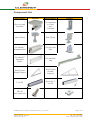
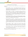
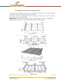
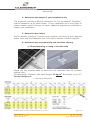
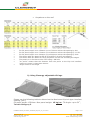
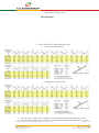
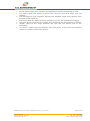
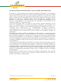
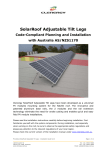
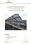
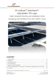
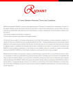
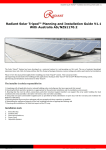
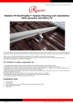
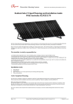
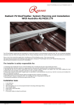
PV-ezRack® SolarRoof™ Klip-Lok Interface Code-Compliant Planning and Installation Complying with AS/NZS1170.2:2011 AMDT 2-2012 CONTENT 1. 2. 3. 4. Introduction…………………………………………………….……………….……………………2 Component List……………………………………………………………..………………………3 Planning……………………………..…………………………………………………………………4 Service…………………………………………………………………………………………………13 Installation Guide_PV-ezRack_SolarRoof_Klip-Lok_AU_V2.1.docx 18/20 Duerdin St Clayton VIC 3168, Australia www.clenergy.com.au Page 1 of 16 Tel: +61 3 9017 6688 Fax: +61 3 9017 6668 Email: [email protected] Introduction The Clenergy PV-ezRack® SolarRoof™ Klip-Lok type interface has been developed as a non-penetrating solution for concealed roofs. The interface can be attached on different type of profiles of concealed roof to mount panels directly or in conjunction with L-feet, tilt legs or SolarTripod. Please review this manual thoroughly before installing PV-ezRack® SolarRoof™. This manual provides (1) supporting documentation for building permit applications relating to PV-ezRack® SolarRoof™ Universal PV Module Mounting System, and (2) planning and installation instructions. The PV-ezRack® SolarRoof™ parts, when installed in accordance with this guide, will be structurally adequate and will meet the AS/NZS1170.2:2011AMDT 22012 standard. During installation and especially when working on the roof please comply with the appropriate occupational health and safety regulations. Please also pay attention to other relevant regulations of your local region. Please check that you are using the latest version of the installation manual, which you can do by contacting Clenergy Australia via email on [email protected], or contacting your local distributor in Australia. Installation Guide_PV-ezRack_SolarRoof_Klip-Lok_AU_V2.1.docx 18/20 Duerdin St Clayton VIC 3168, Australia www.clenergy.com.au Page 2 of 16 Tel: +61 3 9017 6688 Fax: +61 3 9017 6668 Email: [email protected] Component list Part name Picture Description Klip-lok type interface Tin Interface (L-Feet) with Z-Module Inter Clamp End Clamp PV-ezRack® Standard Rail Tilt leg Front Foot PV-ezRack® Standard Splice Tilt leg Back Leg SolarTripod Single Suppot SolarTripod Double Support T rail 50 Splice for T rail 50 Picture M8*25 Hex head bolt Installation Guide_PV-ezRack_SolarRoof_Klip-Lok_AU_V2.1.docx 18/20 Duerdin St Clayton VIC 3168, Australia www.clenergy.com.au Page 3 of 16 Tel: +61 3 9017 6688 Fax: +61 3 9017 6668 Email: [email protected] Planning The installer is solely responsible for: Complying with all applicable local or national building codes and Clean Energy Council guidelines including any that may superseded this manual; Ensuring that PV-ezRack® SolarRoof™ and other products you use are appropriate for the particular installation and the installation environment; Ensuring that the roof, its rafters, connections, and other structural support members can support the array under building live load conditions (this total assembly is hereafter referred to as the roof rafter assembly); Using only genuine PV-ezRack® parts (substitution of parts may void the warranty and invalidate the letter of certification); Ensuring that the concealed roof profile installed on the roof have been identified and is one that is accredited and tested Ensuring the Klip Lok interface fit strongly to the roofing sheet Ensuring safe installation of all electrical aspects of the PV array This document is designed to support for installations using Clenergy Klip-Lok type interface and PV-ezRack® SolarRoof™ (or SolarTripod) PV Module Mounting System, manufactured by Clenergy (Xiamen) Technology Co., Ltd. Follow the six steps below and the installation instructions section to install this product in compliance with the AS/NZS1170.2:2011 AMDT 2-2012. Before proceeding, note the following: This document addresses only wind loads on the assumption that wind produces the maximum load factor affecting an installation. Verify that other local factors, such as snow loads and earth quake effects, do not exceed the wind loads. Give precedence to any factor that does. Wind loads are considered to act on the entire projected area, or may be perpendicular to any surface. The roof on which the PV-ezRack® SolarRoof™ will be installed must have the capacity to resist the combined Design Dead Load and Live Load per footing. To determine the parts (Bill of material) you need, you can use our PVezRack® SolarRoof™ Calculator. Installation Guide_PV-ezRack_SolarRoof_Klip-Lok_AU_V2.1.docx 18/20 Duerdin St Clayton VIC 3168, Australia www.clenergy.com.au Page 4 of 16 Tel: +61 3 9017 6688 Fax: +61 3 9017 6668 Email: [email protected] 1. Determine the wind region of your installation site Region Definition: Wind regions are pre-defined for all of Australia by the Australian Standard 1170.2. The Wind Region is an independent factor of surrounding topography or buildings. Most of Australia is designated Region A which indicates a Regional Ultimate Basic Wind Velocity of 45m/s. Some areas are designated Region B (57m/s). Local authorities will advise if this applies in your area. Region C areas (66m/s) are generally referred to as Cyclonic and are generally limited to northern coastal areas. Most Region C zones end 100km inland. Region D (80m/s) Australia's worst Cyclonic Region between Carnarvon and Pardoo in Western Australia. Installation Guide_PV-ezRack_SolarRoof_Klip-Lok_AU_V2.1.docx 18/20 Duerdin St Clayton VIC 3168, Australia www.clenergy.com.au Page 5 of 16 Tel: +61 3 9017 6688 Fax: +61 3 9017 6668 Email: [email protected] 2. Determine the Terrain Category You will need to determine the terrain category that is most applicable to the installation. Terrain Category 1 (TC1) – Very exposed open terrain obstructions and enclosed, limited-sized water surfaces and ultimate wind speeds in all wind regions, e.g. flat, grassed plains; rivers, canals and lakes; and enclosed less than 10km in the wind direction. with few or no at serviceability treeless, poorly bays extending Terrain Category 1.5 (TC1.5) – Open Water surfaces subjected to shoaling waves at serviceability and ultimate wind speeds in all win regions, e.g. near-shore ocean water; larger unenclosed bays on seas and oceans; lakes; and enclosed bays extending greater than 10km in the wind direction. The terrain height multipliers for this terrain category shall be obtained by the linear interpolation between the values for the TC1 and TC2 in table 4.1. Terrain Category 2 (TC2) – Open terrain, including grassland, with wellscattered obstructions having heights generally from 1.5m to 5m, with no more than two obstructions per hectare, e.g. farmland and cleared subdivisions with isolated trees and uncut grass. Terrain Category 2.5 (TC2.5) – Terrain with a few trees or isolated obstructions. This category is intermediate between TC2 and TC3 and represents the terrain in developing outer urban areas scattered houses, or larger acreage developments with fewer than ten buildings per hectare. The terrain-height multipliers for this terrain category shall be obtained by linear interpolation between the values for the TC2 and TC3 in table 4.1. Terrain Category 3 (TC3) – Terrain with numerous closely spaced obstruction having heights generally from 3m to 10m. The minimum density f obstructions shall be at least the equivalent of 10 house sizes obstructions per hectare, e.g. suburban housing or light industrial estates. Terrain Category 4 (TC4) – Terrain with numerous larger, high(10m to 30m tall) and closely-spaced constructions, such as large city centres and well-developed industrial complexes. Note: In this installation manual we have used terrain category 3, if it is outside of this please refer to the accreditation letter. Installation Guide_PV-ezRack_SolarRoof_Klip-Lok_AU_V2.1.docx 18/20 Duerdin St Clayton VIC 3168, Australia www.clenergy.com.au Page 6 of 16 Tel: +61 3 9017 6688 Fax: +61 3 9017 6668 Email: [email protected] 3. Determine the type of concealed roof The best way to identify the type of concealed roof installed is to check the label normally located underneath the roofing sheet. Otherwise, you can contact the builder or check the building plan to find out the exact type of the roofing sheet. WARNING! THE USE OF THE KLIP-LOK TYPE BRACKET IS NOT ACCREDITED ON ANY OTHER ROOF TYPES THAN THE FOUR LISTED BELOW. Klip-lok 700 ------------------------------------------------------------------ Speed Deck Ultra ------------------------------------------------------------------ KingKlip 700 ------------------------------------------------------------------ Installation Guide_PV-ezRack_SolarRoof_Klip-Lok_AU_V2.1.docx 18/20 Duerdin St Clayton VIC 3168, Australia www.clenergy.com.au Page 7 of 16 Tel: +61 3 9017 6688 Fax: +61 3 9017 6668 Email: [email protected] Klip-lok 406 4. Determine the height of your installation site This document provides sufficient information for the PV-ezRack® SolarRoof™ system installation up 20 meter height. If your installation site is more than 20 meters please contact Clenergy to obtain additional engineering certificate to support your installation. 5. Determine Roof slope The PV-ezRack® SolarRoof™ system can be used for roof slope up to 60 degrees. Please verify that the Installation site roof slope is between 0 and 60 degrees. 6. Determine the maximum Klip-Lok interface spacing a) Direct Mounting or using L-feet and rails Please use the following table to determine the Maximum Klip-Lok interface spacing (mm). PV panel length: 1580mm. Max panel weight: 15 kg/m2. Roof Angle: up to 30˚, Terrain Category 3. On top of the purlin Installation Guide_PV-ezRack_SolarRoof_Klip-Lok_AU_V2.1.docx 18/20 Duerdin St Clayton VIC 3168, Australia www.clenergy.com.au Page 8 of 16 Tel: +61 3 9017 6688 Fax: +61 3 9017 6668 Email: [email protected] Anywhere on the roof For PV panel length over 1580mm up to 1700mm reduce the spacing by 6%. For PV panel length over 1700mm up to 1800mm reduce the spacing by 11.5%. For PV panel length over 1800mm up to 2000mm reduce the spacing by 21%. The above table are based on ER-R-ST and ER-I-09 pull out capacity. The above table are based on fixing anywhere on the roof including the edges. The panels or L-foot have to be fixed using 1 M8 bolt. “on purlin” means that the distance from the purlin to the Klip Lok interface (centre to centre) is less than 100mm Angle refers to roof angle b) Using Clenergy adjustable tilt legs Please use the following table to determine the Maximum Klip-Lok type interface spacing (mm). PV panel length: 1580mm. Max panel weight: 15 kg/m2. Tilt Angle: up to 30˚, Terrain Category 3. Installation Guide_PV-ezRack_SolarRoof_Klip-Lok_AU_V2.1.docx 18/20 Duerdin St Clayton VIC 3168, Australia www.clenergy.com.au Page 9 of 16 Tel: +61 3 9017 6688 Fax: +61 3 9017 6668 Email: [email protected] On top of the purlin Anywhere on the roof For PV panel length over 1580mm up to 1700mm reduce the spacing by 6%. For PV panel length over 1700mm up to 1800mm reduce the spacing by 11.5%. For PV panel length over 1800mm up to 2000mm reduce the spacing by 21%. The above table are based on ER-R-ST, ER-I-09 and ER-TL10/15 and 15/30 pull out capacity. The above table are based on fixing anywhere on the roof including the edges. The feet of the tilt legs have to be fixed using 2 M8 bolt. “Angle” refers to the angle between the roof and the panels (not to the horizontal) “on purlin” means that the distance from the purlin to the Klip Lok interface (centre to centre) is less than 100mm Installation Guide_PV-ezRack_SolarRoof_Klip-Lok_AU_V2.1.docx 18/20 Duerdin St Clayton VIC 3168, Australia www.clenergy.com.au Page 10 of 16 Tel: +61 3 9017 6688 Fax: +61 3 9017 6668 Email: [email protected] c) Using Clenergy PV-ezRack SolarTripod Single Please use the following table to determine the Maximum Klip-Lok interface spacing (mm). PV panel length: 1580mm. Max panel weight: 15 kg/m2. Tilt Angle: up to 30˚, Terrain Category 3. With 2 Klip-Lok interfaces per leg o On top of the purlin o Anywhere on the roof Installation Guide_PV-ezRack_SolarRoof_Klip-Lok_AU_V2.1.docx 18/20 Duerdin St Clayton VIC 3168, Australia www.clenergy.com.au Page 11 of 16 Tel: +61 3 9017 6688 Fax: +61 3 9017 6668 Email: [email protected] With 3 Klip-Lok type interfaces per leg o On top of the purlin o Anywhere on the roof For PV panel length over 1580mm up to 1700mm reduce the spacing by 6%. For PV panel length over 1700mm up to 1800mm reduce the spacing by 11.5%. Installation Guide_PV-ezRack_SolarRoof_Klip-Lok_AU_V2.1.docx 18/20 Duerdin St Clayton VIC 3168, Australia www.clenergy.com.au Page 12 of 16 Tel: +61 3 9017 6688 Fax: +61 3 9017 6668 Email: [email protected] For PV panel length over 1800mm up to 2000mm reduce the spacing by 21%. The above table are based on ER-R-T50, ER-I-09 and ER-S-TRI/S pull out capacity. The last Klip-Lok interface shouldn’t be installed closer than 225mm from the end of the tripod leg. The above table are based on fixing anywhere on the roof including the edges. The base of the tripod have to be fixed using 2 M8 bolt per Klip-Lok type interface “Angle” refers to the angle between the roof and the panels (not to the horizontal) “on purlin” means that the distance from the purlin to the Klip-Lok interface (centre to centre) is less than 100mm d) Using Clenergy PV-ezRack SolarTripod Double Please use the following table to determine the Maximum Klip-Lok type interface Support Spacing (mm). PV panel length: 1580mm. Max panel weight: 15 kg/m2. Tilt Angle: up to 30˚, Terrain Category 3. With 2 Klip-Lok interfaces per leg o On top of the purlin Installation Guide_PV-ezRack_SolarRoof_Klip-Lok_AU_V2.1.docx 18/20 Duerdin St Clayton VIC 3168, Australia www.clenergy.com.au Page 13 of 16 Tel: +61 3 9017 6688 Fax: +61 3 9017 6668 Email: [email protected] o Anywhere on the roof Not suitable With 3 Klip-Lok interfaces per leg o On top of the purlin o Anywhere on the roof For PV panel length over 1580mm up to 1700mm reduce the spacing by 6%. For PV panel length over 1700mm up to 1800mm reduce the spacing by 11.5%. Installation Guide_PV-ezRack_SolarRoof_Klip-Lok_AU_V2.1.docx 18/20 Duerdin St Clayton VIC 3168, Australia www.clenergy.com.au Page 14 of 16 Tel: +61 3 9017 6688 Fax: +61 3 9017 6668 Email: [email protected] For PV panel length over 1800mm up to 2000mm reduce the spacing by 21%. The above table are based on ER-R-T50, ER-I-09 and ER-S-TRI/S pull out capacity. The last Klip-Lok type interface shouldn’t be installed closer than 500mm from the end of the tripod leg. The above table are based on fixing anywhere on the roof including the edges. The base of the tripod has to be fixed using 2 M8 bolt per Klip-Lok type interface. “Angle” refers to the angle between the roof and the panels (not to the horizontal) “on purlin” means that the distance from the purlin to the Klip Lok interface (centre to centre) is less than 100mm Installation Guide_PV-ezRack_SolarRoof_Klip-Lok_AU_V2.1.docx 18/20 Duerdin St Clayton VIC 3168, Australia www.clenergy.com.au Page 15 of 16 Tel: +61 3 9017 6688 Fax: +61 3 9017 6668 Email: [email protected] 1. Service 10 year limited Product Warranty, 5 year limited Finish Warranty Clenergy co. Ltd warrants to the original purchaser (“Purchaser”) of product(s) that it manufactures (“Product”) at the original installation site that the Product shall be free from defects in material and workmanship for a period of ten (10) years, except for the anodised finish, which finish shall be free from visible peeling, or cracking or chalking under normal atmospheric conditions for a period of five (5) years, from the earlier of 1) the date the installation of the Product is completed, or 2) 30 days after the purchase of the Product by the original Purchaser (“Finish Warranty”). The Finish Warranty does not apply to any foreign residue deposited on the finish. All installations in corrosive atmospheric conditions are excluded. The Finish Warranty is VOID if the practices specified by AAMA 609 & 610-02 – “Cleaning and Maintenance for Architecturally Finished Aluminium” (www.aamanet.org) are not followed by Purchaser. This Warranty does not cover damage to the Product that occurs during its shipment, storage, or installation. This Warranty shall be VOID if installation of the Product is not performed in accordance with Clenergy’s written installation instructions, or if the Product has been modified, repaired, or reworked in a manner not previously authorized by Clenergy IN WRITING, or if the Product is installed in an environment for which it was not designed. Clenergy shall not be liable for consequential, contingent or incidental damages arising out of the use of the Product by Purchaser under any circumstances. If within the specified Warranty periods the Product shall be reasonably proven to be defective, then Clenergy shall repair or replace the defective Product, or any part thereof, in Clenergy’s sole discretion. Such repair or replacement shall completely satisfy and discharge all of Clenergy’s liability with respect to this limited Warranty. Under no circumstances shall Clenergy be liable for special, indirect or consequential damages arising out of or related to use by Purchaser of the Product. Manufacturers of related items, such as PV modules and flashings, may provide written warranties of their own. Clenergy’s limited Warranty covers only its Product, and not any related items. Installation Guide_PV-ezRack_SolarRoof_Klip-Lok_AU_V2.1.docx 18/20 Duerdin St Clayton VIC 3168, Australia www.clenergy.com.au Page 16 of 16 Tel: +61 3 9017 6688 Fax: +61 3 9017 6668 Email: [email protected]