1
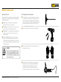
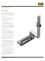
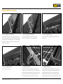
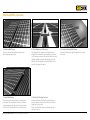
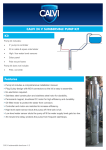
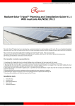
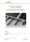
Rooftop Installation Manual
Version 4.1 – updated February 2012
Australian
Made
www.sunlock.com.au
contents
Introduction
3
Consumer Guarantees
19
Safety and Installer Responsibilities
Handling and Installing SunLock
Wind and Climate Design
4
Contact Details
19
Maintenance and Cleaning
20
Technical Specifications
Applications
Features
Custom Design
5
References
20
Certificate of Compliance
20
21
Before Installing
Receipt of Goods
6
Technical Drawings
S1
S2
S3
S4
S5
S6
S7
S8
S9
S10
Tools Required for Installation
SunLock Components
4
4
5
5
5
6
6
7
Designing Your Framing System
11
Fixing Locations and Array Placement
12
Wind Region Map Australia (in accordance
with AS/NZS1170.2:2011)
13
Installation
14
Installing Tile Brackets
15
Rooftop installation manual – Version 4.1 (updated February 2012)
22
23
24
25
26
27
28
29
30
14
Installing L-Feet on Steel Roofs
Warranty Against Defects
21
18
2
Introduction
Thank you for choosing the SunLock solar panel roof
mounting system. Made from custom-designed aluminium
extrusions and components, SunLock’s streamlined
design and improved frame strength greatly simplify
solar panel installation.
Offering a high level of adjustability for module width and
depth SunLock’s versatile design makes it suitable for
a wide variety of building types and zones including
residential, commercial and remote environments.
SunLock is backed by a 10-year warranty and is
compliant with the AS/NZS1170.2:2011 on wind
actions, AS/NZS16641.1:1997 on aluminium structures,
AS1720.1:2012 on timber structures, AS/NZS4600:2005
on cold-formed steel structures.
WARNING
Indicates a potentially hazardous situation
which, if not avoided, could result in death
or serious injury. This symbol is not used for
hazards relating to property damage unless
there is also a risk of personal injury to this level.
CAUTION
Indicates a potentially hazardous situation
which, if not avoided, may result in minor or
moderate injury. It may also be used to draw
attention to unsafe practices that may cause
damage to property.
Rooftop installation manual – Version 4.1 (updated February 2012)
3
Safety and Installer Responsibilities
Handling and Installing SunLock
Wind and Climate Design
It is critically important that safety practices are
observed when installing SunLock.
A SunLock frame installed in accordance with this
installation manual is compliant with AS1170.2:2011.
Do not throw or roughly handle any SunLock components.
Do not bring SunLock into contact with sharp
or heavy objects.
Do not modify SunLock components in any way.
The exchange of bolts, drilling of holes, bending or
any other physical changes not described in standard
installation procedure will void the warranty.
It is the installer’s responsibility to verify the integrity
of the structure to which SunLock is fixed. Roofs or
structures with rotten/rusted purlins, undersized purlins,
excessively spaced purlins, or any other unsuitable
substructure cannot be used with SunLock, and
installation on such structures will void the warranty, and
could result in death or serious injury.
This manual (including the drawings) cannot cover all
types of buildings and eventualities.
INSTALLATION OF THIS PRODUCT IS TO BE
PERFORMED ONLY BY PROFESSIONALLY
TRAINED INSTALLERS.
Any attempt by an unqualified person to install this
product could result in death or serious injury.
For buildings outside the limits stated on the drawings
(maximum 10 m roof height, maximum roof pitch 35°,
slopes, hills) contact a structural engineer for a
custom design.
AS/NZS1170.2:2011 provides guidance on determining
the wind pressures applicable to your SunLock install site,
taking into account roof shape and geographic location.
Sufficient guidance is given in this document, but you may
wish to procure a copy of these standards if your company
installs Australia/New Zealand wide.
REMEMBER average wind speeds are higher for
structures mounted closer to the roof perimeter
zone (edge).
Make sure your installation complies with local and
national building codes. Take into account relevant
design parameters (wind speed, exposure and
topographic factor) when determining the loading
for the installation.
If alternative fasteners are used to fix the framing to
the roof (assuming supplied fasteners are unsuitable
for any reason), all screw fasteners must conform to
corrosion resistance Class 4 Australian Standard
AS3566 and be of equal or greater strength to those
supplied with your SunLock order.
Rooftop installation manual – Version 4.1 (updated February 2012)
4
Technical Specifications
Applications
Commercial and residential buildings
Marine applications and remote areas
Features
Custom Design
A SunLock frame can be designed to suit almost any roof
and wind region, including buildings up to 200 m in height,
roof pitches up to 65°, and located on slopes or hills.
For a custom design please contact a structural engineer.
6106-T6 aluminium extrusion with 210 MPa yield strength
Ripple design on rail, L-foot and tile brackets increases
joint strength
Suitable for buildings up to 10 m in height
Suitable for roof slopes in the range from 0° to 35°
Inherent corrosion resistance resulting in low ongoing
maintenance and an extended product life.
Complies with Australian/New Zealand Standard on
Wind Actions, AS/NZS1170.2:2011
Optional anodised finish (standard is mill finish)
Australian design and manufacture
Rooftop installation manual – Version 4.1 (updated February 2012)
5
Before Installing
Receipt of Goods
Check that the SunLock equipment is undamaged and
that the order is complete. Check for correct quantities
of the following items:
Rails: slightly more than twice the length of the
proposed solar array in linear metres
End clamps: a minimum of 4 per row (unless 3 rails
are required) of panels (fitted at the ends)
Tools Required for Installation
T-bar Allen Key or 6 mm hexagonal driver bit. If using
a 6 mm driver bit, make sure the cordless power tool
used for driving has a hand-tight clutch setting and a
fine (soft) impact drive to prevent damage to the fragile
glass panels and threads on the SunLock framing.
Drill or impact driver for driving roof material fixings.
Mid clamps: 2 for every gap between neighbouring
panels, e.g. number of panels in row, minus one,
multiplied by two.
L-feet or Tile Brackets: at least 2 for each panel;
L-feet, roof screws and isolation washers for steel
roof interfaces; tile brackets and rafter screws for tile
roofs. Refer to the drawings to determine the number
of fixings required.
caution
Gloves for handling SunLock framing (aluminium can
develop sharp corners).
Refer to the section ‘Designing Your Framing
System’ before attempting installation. Failure
to correctly establish the requirements of the
proposed installation site is dangerous and will
void the framing warranty.
For terracotta tile roof installation, an angle grinder
fitted with a continuous edge diamond tipped tilecutting blade; gloves, hearing protection, a face
protection mask, and a suitably rated breathing
protection mask for all people in proximity of grinding.
Rooftop installation manual – Version 4.1 (updated February 2012)
6
SunLock components
SLR – Rails, in pairs, hold each panel row and are
custom designed and Australian made 6106-T6
extruded aluminium.
Note: custom rail lengths available on request.
Minimum order quantity, deposit & lead time apply.
SLJ150 – Joiners extend SunLock Rails to any length
as required by the quantity or width of the solar panels.
SLLF – L-foot roof mounts secure the railing to steel roofs.
Each L-foot is supplied with a potable grade EPDM
washer to prevent water ingress or galvanic corrosion
with the roof material.
SLLF002 – standard, with a 75 mm roofing screw
SLLF004 – with a Tek screw
SLLF005 – with a 10 mm hole in the base
SLLF006 – with a slot in the base
Rail lengths
For standard 808 mm
wide panels
For wider 990 - 1005 mm
wide panels
2600 mm
2100 mm
3410 mm
3200 mm
4200 mm
Rooftop installation manual – Version 4.1 (updated February 2012)
7
SunLock components (continued)
SLTB002 – Tile brackets fix the railing to the rafters
below a tile roof and ensure a waterproof finish. Each tile
bracket includes two 75 mm roofing screws. If attaching
to hardwood of minimum joint group JD2, these can be
substituted by 45 mm screws.
Rooftop installation manual – Version 4.1 (updated February 2012)
SLTB004 – Adjustable tile brackets allow adjustment of
the elevation and side position of the bracket to provide a
closer fit for different tile batten heights, tile profiles, and
tile positions. Each tile bracket includes two 75 mm roofing
screws. If attaching to hardwood of minimum joint group
JD2, these can be substituted by 45 mm screws.
SLECF - Fixed end clamps are available in 35, 38, or
45 mm heights, and are simple and fast to install.
SLECF35 – 35 mm panels
SLECF38 – 38 mm panels
SLECF45 – 45 mm panels
8
SunLock components (continued)
LEC – Adjustable End Clamps allow the easy
S
modification of the clamp to suit almost any panel frame
height. Note: Minimum of two fins must be engaged.
SLMC – Mid clamps fit between panels and hold the
panels to the rails. Two variations are available, differing
only by the length of the cap screw.
SLEC003 – 30 - 42 mm panels
SLMC004 – 30 - 40 mm panels
SLEC004 – 34 - 46 mm panels
SLMC006 – 40 - 50 mm panels
Note: Other panel thickness accommodated by
special orders.
SLEC006 – 46 - 58 mm panels
Rooftop installation manual – Version 4.1 (updated February 2012)
SLEL – EarthLock system comprises the EarthLock
washer (SLELW) and the EarthLock bonding terminal
(SLELBT). This system provides earth continuity from
each panel frame to the rail, allowing the quick and
effective connection of the array to an earthing cable
if required.
9
SunLock components (continued)
SLIMB – Isolator Mounting Bracket is easily attached to
the SunLock rail and provides a mounting surface for the
rooftop DC isolator.
SLTL – Tilt Leg kits comprise one front leg and one rear
leg. The front leg is 150 mm long.
SLTL500 – 500 mm rear leg
SLCA – Channel Assembly allows tilt arrays to be
correctly inclined, even if the purlins are not ideally spaced
or located. The channel has outer dimensions of 41.3 x
41.3 mm and is extruded from 6061-T6 structural grade
aluminium with a minimum yield strength of 240 MPa.
SLTL600 – 600 mm rear leg
SLCA1500 – 1500 mm long, 1 L-foot
SLTL700 – 700 mm rear leg
SLCA2000 – 2000 mm long, 2 L-foot
SLTL800 – 800 mm rear leg
SLCA3000 – 3000 mm long, 2 L-foot
SLTL300 – 300 mm rear leg
Note: a diagonal brace (SLDB1200) should be used at
each end of each row of the tilt array.
Rooftop installation manual – Version 4.1 (updated February 2012)
10
Designing Your Framing System
Design your system:
1. Select the correct drawing
2. Determine the width of the edge zone
3.Read off the maximum fixing spacing
and calculate the total number of
fixings required
The ten drawings are as follows:
S1 –Tile roofs of pitch 10 - 20°
S2 –Tile roofs of pitch 20 - 35°
S3 –Tin roofs of pitch 10 - 20° with steel purlins
S4 –Tin roofs of pitch 20 - 35° with steel purlins
S5 –Tin roofs of pitch 10 - 20° with timber purlins
S6 –Tin roofs of pitch 20 - 35° with timber purlins
S7 –Tilt legs on roofs with steel purlins
S8 –Tilt legs on roofs with timber purlins
S9 – Tile roofs of pitch 10 - 20° (terrain category 3)
S10 – Tile roofs of pitch 20 - 35° (terrain category 3)
The installation site, roof material, roof angle, the size and
quantity of solar panels and the number of module rows
used will determine the dimensions, quantity and layout of
framing components required for installation. This section
of the installation manual can assist you to determine
critical job specifications.
Rooftop installation manual – Version 4.1 (updated February 2012)
In most cases the SunLock frame itself (rails and clamps)
is strong enough to withstand any wind load. When
designing the frame, the two main points to consider are:
ensuring sufficient fixings are used to hold the
SunLock frame to the roof frame
ensuring the roof frame itself is not overloaded by
the extra wind load from the solar system
Ten drawings have been supplied with this installation
manual, one for each roof type. Select the appropriate
drawing for the installation site and follow the detailed
instructions contained within it.
Note the following details:
When a panel ‘covers’ three roof battens, then three rails
should be used. This ensures that the battens are not
overloaded by the point loads from the L-feet. In other words,
for tin roof installations where the purlin spacing is less than
750 mm, three rails should be used per row of panels.
Ensure panels are installed in accordance with the solar
panel manufacturer’s installation manual. Typically, these
manuals state that the clamps holding the panel to the
rail must be installed in a certain region, commonly a
maximum of 10-25% of the length of the panel from each
end of the panel.
11
Fixing Locations and Array Placement
Solar panels can be installed anywhere on the roof, as
long as sufficient fixings are used. Higher wind speeds
are encountered at the edges of roofs and therefore more
fixings are required in these areas.
A roof can be divided into three zones, the internal zone,
intermediate zone and the edge zone. The width of these
outer zones can be determined based on the length, width
and average height of the building.
If fixings are located in the intermediate or edge zones,
then the maximum spacing to the next fixing must be
reduced, as per the table in the drawings.
Determining the width of the edge and
intermediate zones, ‘A’
The width of the edge and and intermediate zones,
‘A’, is determined by calculating each of the following
values, and then using the smallest:
0.2 x B
0.2 x D
H
Rooftop installation manual – Version 4.1 (updated February 2012)
12
Wind Region Map Australia (in accordance with AS/NZS1170.2:2011)
Included towns:
Region A:
Callytharra Springs
Gascoyne Junction
Green Head
Kununurra
Lord Howe Island
Morawa
Toowoomba
Wittanoom
Bourke
Region B:
Adelaide River
Atherton
Biloela
Brisbane
Christmas Island
Collinsville
Corindi
Geraldton
Ivanhoe
Kyogle
Marble Bar
Mullewa
Norfolk Island
Torres Strait Islands
Wyndham
Region C:
Borroloola
Broome
Bundaberg
Burketown
Cairns
Cocos Islands
Darwin
Derby
Karumba
Mackay
Mareeba
Millstream
Moreton
Nhulunbuy
Normanton
Rockhampton
Townsville
Region D:
Carnarvon
Exmouth
Karratha
Onslow
Port Hedland
Rooftop installation manual – Version 4.1 (updated February 2012)
50km
100km
150km
20˚
25˚
27˚
25˚
30˚
30˚
Region A
Region B
Region C
Region D
13
Installation
Start any roof/structure installation by marking the fixing
points at the calculated centres and spacing along
the proposed length of the array (in a parallel row).
Installing L-Feet on Steel Roofs:
For a steel roof with exposed fixings
1.Determine where the roof mounts will be positioned
based on position of existing roof screws.
2.Do not remove existing roof screws. Instead, install
on unused crest. This is because the existing screws
are there to hold down the roof sheet, while the new
screws are there to hold down the solar system.
or a steel roof with hidden fixings
F
(clip-type roofing)
1. Lift the sheets of steel to expose the structure beneath.
2.Using a marker, mark out the precise locations of the
structure below the roofing material and clip the roof
back in place.
3.Fix L-feet in place and fix with the upright part of the
‘L’ facing towards the ridge of the roof.
3.Place L-feet on the markings and screw down with
supplied isolation washers between the base of the
foot and the roof surface.
4.Secure the L-foot roof mounts with the roof screws.
Use the supplied isolation washers between the base
of the L-foot and the roof surface.
Note: SunLock can only be attached to “406” style
roof sheets. Use a 90 mm screw instead of the
supplied 75 mm.
L-foot fits to the crest
Rooftop installation manual – Version 4.1 (updated February 2012)
14
Installation
(continued)
Installing Tile Brackets
Installation of the SLTB004 Adjustable Tile Bracket
requires no special tools – only a 13 mm socket/spanner
and the 6 mm internal hex driver/Allen key normally used
for SunLock framing.
Expose the timber rafters where the SunLock Tile
Brackets are to be attached by sliding or removing
tiles at a suitable spacing
Loosely assemble the tile brackets ready for
adjustment. Place the first tile bracket on a rafter
and adjust the elevation to a low and flush fit. Use a
13 mm socket to secure the bolt assembly. Generally,
the other brackets on the roof can be adjusted to the
same elevation position.
Attach the tile brackets to the rafters using the
supplied screws. To prevent splitting the timber,
pre-drill the screw holes at an inward facing angle.
This is especially important for hardwood rafters.
Move the tiles back into place. Attach the SunLock
rails to the Adjustable Tile Bracket uprights, and your
framing installation is nearly complete.
Tile brackets are supplied as standard with 75 mm
timber roofing screws, which supply the required 70 mm
embedment in softwood rafters. For hardwood rafters,
the embedment can be reduced to 40 mm (i.e. use at
least a 45 mm screw, or longer if you have any packers
between the tile bracket and the rafter).
If the purlins are steel (e.g. cold formed galvanized
c-sections), note that Tek screws cannot be used unless
the purlin is at least 3 mm thick, as they do not have
sufficient pull out capacity. Other options are to position
a section of timber in the section and screw into the
timber, or use bolts, washers and nuts.
Rooftop installation manual – Version 4.1 (updated February 2012)
15
Installation
(continued)
1. Connecting Rail to Roof Mounts
Connect the rail to the roof mounts by inserting the roof
mount keylock into the rail channel. Make sure the ridged
rail surface faces the ridged surface of roof attachments.
Fasten the cap screw on the keylock 2-3 turns to loosely
hold the rail in position.
2. Connecting Rail to Roof Mounts
The rail can be adjusted vertically within the roof
attachment slot when bolts are loosely fastened.
3. Connecting Multiple Rails
Join rail segments by inserting the rail joiner into the
rail channel.
4. Connecting Multiple Rails
Fasten cap screws to secure.
5. Installing End Clamps
Insert keylock of the end clamp into the rail channel.
Using a 6 mm hex driver/Allen key, secure the first solar
panel to the railing starting as close to the end of the row
as possible. A minimum of 50 mm between the end of
the rail and edge of the first solar panel is required.
6. Installing Mid Clamps
Insert the keylock of the mid clamp into the rail channel
and position the clamp against the first panel frame. Handtighten the screw 2-3 turns to loosely hold the clamp in
position. If EarthLock washers are used, they should be
placed between the SunLock rail and the frame of the panel.
Rooftop installation manual – Version 4.1 (updated February 2012)
16
Installation
(continued)
7. Installing Mid Clamps
Slide second panel firmly into place against the
mid clamps and fasten bolts.
8. Check Alignment of the Array
After fixing the first 2 panels, check that the array is
straight. If there appears to be a deviation from square
(e.g. if the ridge cap shows the row to be falling or rising
slightly), readjust the panels until they appear square
with the roof. Alternatively, measure the distance from
the rail to the edge of the panel.
10. Install End Clamps
Finish the array row by securing the remaining two
end clamps. You should have a minimum of 50 mm
clearance between the edge of the last panel and the
end of the rail. Tighten all bolts to secure the panels.
11. EarthLock Bonding Terminal
Fasten the EarthLock Bonding Terminal directly to a
SunLock rail by placing the insert key in the rail and
tightening the cap screw.
Note: The SLELBT02 can be connected to the top or
the side of the rail.
Rooftop installation manual – Version 4.1 (updated February 2012)
9. Continue Installing Mid Clamps
Continue to clamp the neighbouring panels in the array
to the rails.
17
WARRANTY AGAINST DEFECTS
Energy Matters Pty Ltd (trading as Energy Matters and
Apollo Energy) (Energy Matters) is the manufacturer of
the Sunlock Solar Module Mounting System (Frame).
Energy Matters warrants, on the terms set out below,
that the Frame will be free from defects in materials
and workmanship for a period of 10 years from the date
on which the Frame is purchased from Energy Matters
(Warranty against Defects).
Transferability
Our Warranty against Defects is only provided to the
original purchaser of the Frame from Energy Matters
(Purchaser) or, where the Purchaser is an installer or
builder who on-supplies the Frame to another party, to that
other party (End-User). Our Warranty against Defects is
not otherwise transferable.
Making a claim
If you believe that the Frame is defective and you are an
End-User, you may either make a claim against the installer
or builder from whom you purchased the Frame or you
may make a claim against us directly.
In order to make a claim against us, you must post, fax or
email us a notice, using the contact details set out below.
In your notice you must provide:
details of why you believe the Frame is defective;
a copy of your invoice, receipt or any other document
which provides proof of purchase;
details of any expenses you have incurred in making
your claim; and
details of how we should contact you.
Rooftop installation manual – Version 4.1 (updated February 2012)
Within a reasonable time after receipt of your claim we will
contact you to arrange a time to attend the premises at
which the Frame is located.
Remedies
If we determine that the Frame is defective and the
defect is not a major failure then, if possible, we will try to
repair the defective Frame at the premises. If this is not
possible, we will remove the defective Frame and provide
a replacement Frame at our expense.
If we determine that the Frame is defective and the defect
is a is major failure then you have the option of rejecting the
Frame and obtaining a refund from us, rejecting the Frame
and obtaining a replacement Frame from us at our expense
or of keeping the Frame and receiving compensation from
us for the difference between the actual value of the Frame
and the amount you paid for the Frame.
Exclusions
Our Warranty against Defects does not include:
damage caused to the Frame during shipment or storage
of the Frame by a party other than Energy Matters;
damage caused to the Frame during installation by a
party other than Energy Matters;
damage caused by ‘Acts of God’, vermin, animals
or pests or by other causes or acts outside Energy
Matters’ reasonable control; or
normal wear and tear, including normal weathering.
Jurisdiction
Our Warranty against Defects is to be construed in
accordance with the laws of Victoria and any disputes
will be determined by the exclusive jurisdiction of the
courts of Victoria.
If we determine that the Frame is defective we will also pay
the substantiated reasonable expenses incurred by you in
making your claim.
Your obligations
In order to have the benefit of our Warranty against Defects:
if you are a Purchaser, you must have paid all amounts
owed by you to Energy Matters in relation to the
purchase of the Frame;
you must have complied with all reasonable instructions
of Energy Matters (whether written or verbal) in relation
to the transport, installation, care, repair and use of the
Frame; and
you must not have misused, neglected, damaged or
modified the Frame.
18
CONSUMER GUARANTEES
Contact Details
In addition to our Warranty against Defects, the Frame also
comes with guarantees that cannot be excluded under the
Australian Consumer Law (Consumer Guarantees).
Energy Matters Pty Ltd (trading as Energy Matters
and Apollo Energy)
In the event that the Frame fails to satisfy a Consumer
Guarantee, you are entitled to a replacement or refund for
a major failure and compensation for any other reasonably
foreseeable loss or damage. You are also entitled to have
the Frame repaired or replaced if the Frame fails to be of
acceptable quality and the failure does not amount to a
major failure.
Please note that in addition to the rights and remedies set
out in this document, you may also have other rights and
remedies available to you under the law.
Rooftop installation manual – Version 4.1 (updated February 2012)
Address: Level 2, 101-105 Clarke Street,
South Melbourne, VIC, 3205
Postal Address: PO Box 5265, South Melbourne,
VIC, 3205
Sales and Service:
1300 855 484 (local call from anywhere in Australia)
International: +61 3 9697 1990
Fax: +61 3 9697 1919
Email: [email protected]
19
MAINTENANCE AND CLEANING
CERTIFICATE OF COMPLIANCE
6106-T6 aluminium is largely maintenance free. Only in
highly polluted or marine conditions is rinsing with
clean water required, during scheduled panel cleaning.
REFERENCES
AS/NZS1170.2:2011 on wind actions
AS/NZS16641.1:1997 on aluminium structures
AS1720.1:2012 on timber structures
AS/NZS4600:2005 on cold-formed steel structures
AS3566-2011, self-drilling screws for the building
and construction industries.
Rooftop installation manual – Version 4.1 (updated February 2012)
20
PRODUCT NAME
PRODUCT DESCRIPTION
MANUFACTURER'S NAME
DESIGN CRITERIA
LIMITATIONS
PRODUCT NAME
PRODUCT DESCRIPTION
MANUFACTURER'S NAME
DESIGN CRITERIA
LIMITATIONS
PRODUCT NAME
PRODUCT DESCRIPTION
MANUFACTURER'S NAME
DESIGN CRITERIA
LIMITATIONS
PRODUCT NAME
PRODUCT DESCRIPTION
MANUFACTURER'S NAME
DESIGN CRITERIA
LIMITATIONS