1
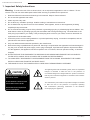
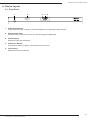
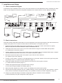
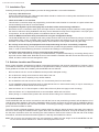
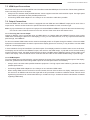
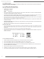
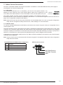
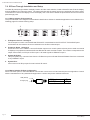
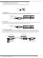
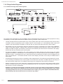
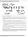
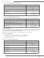
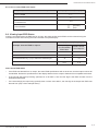
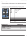
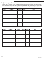
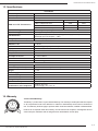
Installation Manual
B-500-MTRX-230-4x4
Binary™ HDMI Matrix Switcher
with HDMI and HDBaseT Outputs
B-500-MTRX-230-4x4 Installation Manual
1. Important Safety Instructions
Warning:
To reduce the risk of fire or electric shock, do not expose this apparatus to rain or moisture. Do not
remove cover. No user serviceable parts inside. Refer servicing to qualified service personnel.
1. Read and follow all instructions and warnings in this manual. Keep for future reference.
2. Do not use this apparatus near water.
3. Clean only with a dry cloth.
4. Do not block any ventilation openings. Install according to manufacturer’s instructions.
5. Do not install near any heat sources such as radiators, heat registers, stoves or other apparatus (including
amplifiers) that produce heat.
6. Do not override the safety purpose of the polarized or grounding-type plug. A polarized plug has two blades - one
wider than the other. A grounding type plug has two blades and a third grounding prong. The wide blade or the
third prong is provided for your safety. If the provided plug does not fit into your outlet, consult an electrician for
replacement of the obsolete outlet.
7. Protect the power cord from being walked on or pinched particularly at plug, convenience receptacles, and the
point where it exits from the apparatus.
8. Only use attachments/accessories specified by the manufacturer.
9. Refer all servicing to qualified service personnel. Servicing is required when the apparatus has been damaged in
any way, such as when the power-supply cord or plug is damaged, liquid has been spilled or objects have fallen
into the apparatus, the apparatus has been exposed to rain or moisture, does not operate normally, or has been
dropped.
10. DO NOT EXPOSE THIS EQUIPMENT TO DRIPPING OR SPLASHING AND ENSURE THAT NO OBJECTS
FILLED WITH LIQUIDS, SUCH AS VASES, ARE PLACED ON THE EQUIPMENT.
11. TO COMPLETELY DISCONNECT THIS EQUIPMENT FROM THE AC MAINS, DISCONNECT THE POWER
SUPPLY CORD PLUG FROM THE AC RECEPTACLE.
12. THE MAINS PLUG OF THE POWER SUPPLY CORD SHALL REMAIN READILY OPERABLE.
CAUTION
CAUTION: TO REDUCE THE RISK OF
ELECTRICAL SHOCK.
DO NOT REMOVE COVER. NO USER
SERVICEABLE PARTS INSIDE.
REFER SERVICING TO QUALIFIED
SERVICE PERSONNEL.
The lightning flash with arrowhead symbol, within an equilateral
triangle, is intended to alert the user to the presence of
un-insulated dangerous voltage within the product’s enclosure
that may be of sufficient magnitude to constitute a risk of electric
shock to persons.
The exclamation point within an equivalent triangle is intended
to alert the user to the presence of important operating
and maintenance (servicing) instructions in the literature
accompanying the appliance.
Pg. 2
© 2013 Binary™
B-500-MTRX-230-4x4 Installation Manual
Table of Contents
1. Important Safety Instructions
2. Product Overview
3. Package Contents
4.Features
5. Recommended for Installation
6. Device Layout
6.1. Front Panel
6.2. Rear Panel
7. Installation Setup
7.1. Basic Installation Diagram
7.2. Basic Instructions
7.3. Installation Tips
7.4. Switcher Location and Placement
7.4.1. Rack Installation
7.5. HDMI Input Connections
7.6. Output Connections
7.6.1. Choosing the Correct Output
7.6.2. HDMI Outputs
7.6.3. HDBaseT Outputs
7.7. Matrix Control Connections
7.7.1. IR Control
7.7.2. RS232 Control
7.8. IR Pass-Through Installation and Setup
7.8.1. Matrix Switcher IR Connections
7.8.2. Matrix Switcher IR Port Configuration
7.9. B-500-RX-230-IR IR Connections
7.9.1. IR Receiver
7.9.2. IR Flasher
7.9.3. Yellow Tag IR Adapter
7.10.IR Application Diagrams
7.10.1. IR Pass-Through from Control System
7.10.2. IR Pass-Through from Rooms to Sources
8. EDID Configuration
8.1. Source Setup
8.2. Display Setup
8.3. Auto EDID Configuration
8.3.1. How to Configure Auto EDID
8.4. Embedded EDID Configuration
8.4.1. Embedded EDID Chart
8.4.2. How to Set Embedded EDID for a Single Input
8.4.3. How to Set Embedded EDID for All Inputs
8.5. EDID Learning
8.5.1. How to Learn EDID to a Single Input
8.5.2. How to Learn EDID to a All Inputs
8.6. Viewing Input EDID Status
9. Advanced Setup Using the Configuration Utility
9.1. IR Source Routing
9.2. IR Front Panel IR Enable
9.3. Matrix Control from Room Enable
9.4. Front Panel Power Button Active
10. Firmware Update
11. Operation and Control
11.1. IR Remote
11.1.1. Route Inputs to Outputs
11.1.2. Turn Off (Mute) Outputs
11.1.3. Display Output Status
11.1.4. Resetting to Factory Defaults
12.Troubleshooting
12.1. General Troubleshooting Guidelines
12.2. No Signal from Source to any Display
12.3. No Signal from any Source to an Display
12.4. Audio issues
13. Contacting Tech Support
14. System Layout Chart
15. Specifications
16.Warranty
2
4
4
4
4
5
5
6
7
7
7
8
8
8
9
9
9
9
10
11
11
11
12
12
12
13
13
13
13
14
14
15
16
16
16
16
16
17
17
18
18
18
18
19
19
20
20
20
20
20
20
21
21
21
22
22
23
24
24
24
24
25
25
26
27
27
Pg. 3
www.snapav.com Support: 866.838.5052
B-500-MTRX-230-4x4 Installation Manual
2. Product Overview
Welcome to Binary™, one of the most highly regarded brands available today. This product is engineered to
provide years of exceptional reliability. We appreciate your business and we stand committed to providing our
customers with the highest degree of quality and service in the industry.
The B-500-MTRX-230-4x4 is a state-of-the-art HDMI matrix switcher with both HDMI and HDBaseT Outputs. It provides
true matrix routing for HDMI signals. With features such as HDMI 3D support, sophisticated EDID handling, IR, and
RS232, this product is ideal for residential and commercial media distribution systems. The HDBaseT connection on
each output extends HDMI signals and bi-directional IR to remote rooms up to 230 feet away via Cat5e/Cat6/Cat6a.
Note: This manual covers all aspects of installation and setup of the B-500-MTRX-230-4x4 for most applications. Some
features must be configured using the Configuration Utility software. Go to the product page for the B-500-MTRX230-4x4 at www.SnapAV.com and click on the Support Tab to download the Configuration Utility and manual.
3. Package Contents
•
•
•
(1) B-500-MTRX-230-4x4
(2) Rack ears for mounting (screws included)
(1) IR Remote Control
•
•
•
(1) Power supply 24V 2.7A DC
(1) Installation Manual
(1) CD-ROM
4.Features
•
(4) HDMI inputs by (4) mirrored HDMI and HDBaseT outputs
•
Up to 8 displays can be attached in total (using both HDMI and HDBaseT outputs)
•
Supports Video resolutions up to1080p/60 36bit color
•
Supports all HDMI audio formats including Dolby True HD and DTS Master HD
•
Supports all HDMI 3D formats
•
Sophisticated EDID handling including Embedded, Learned, and Auto modes
•
HDMI or DVI with adapter (not included)
•
IR Control from integrated receiver or 3.5mm input
•
Bi-directional IR pass-through when using B-500-RX-230-IR
•
Home Automation Control via IR, and RS-232
•
PC Setup and Configuration using dedicated software
•
HDCP 2.0 compliant
•
CEC Pass Through
5. Recommended for Installation
•
Phillips Screwdriver (for rack ear attachment)
•
Up to 4 sources
•
Up to 4 displays (8 if using both HDBaseT and HDMI outputs, see Section 7.6, Page 9)
•
Binary High Speed HDMI Cables to connect sources to B-500-MTRX-230-4x4 HDMI inputs
•
Binary HDMI cables or B-500-RX-230-IR units and Cat 5e/6 cable installed between matrix switcher location and
displays (See section 7.6.3.1, page 10 for HDBaseT wiring recommendations)
•
RJ45 connectors and termination tools (If using B-500-RX-230-IR)
•
Control System to control operation of B-500-MTRX-230-4x4
•
Windows PC with Configuration Utility installed and RS232 adapter
•
Configuration Utility Manual
Pg. 4
© 2013 Binary™
B-500-MTRX-230-4x4 Installation Manual
6. Device Layout
6.1.Front Panel
1
2
3
4
5
1. Power On/Off Switch
Toggle Power from On to Stand-by. Can be disabled from Configuration Utility software.
2. Source Status LEDs
Indicates that the selected source is on and transmitting an HDMI signal. 3. Output Display
Displays the last output selected.
4. IR Receiver Window
IR receiver for Matrix to capture commands sent by IR remote.
5. Input Display
Displays the last input selected.
Pg. 5
www.snapav.com Support: 866.838.5052
B-500-MTRX-230-4x4 Installation Manual
6.2.Rear Panel
1
2
3
4
1
3
2
4
LINK
5 6
7
LINK
LINK
LINK
8
1
3
2
4
9
10
24V DC 2.7A
1. HDMI Inputs 1 through 4
Connect HDMI cables from sources to the matrix switch for distribution.
2. RS-232 control port (DB9)
Attach connection from control system or Windows PC for serial control of the B-500-MTRX-230-4X4.
3. IR Output to Source 1 through 4
3.5mm mono mini connections used to connect IR flashers for controlling sources. These ports may be configured to
route commands only from the IR output corresponding to the HDBaseT output number (IR zone routing), or directly
to the source selected for viewing on an HDBaseT output (IR source routing). (See Configuration Utility)
4. RJ45 HDBaseT Outputs 1 through 4
Connect 568B terminated Cat5e/6 HDBaseT cable routed to a B-500-RX-230-IR up to 230 feet away to feed HDMI
signal to display. Output simultaneously displays the same source as the HDMI output of the same number.
5. Link LED
The green Link LEDs indicate the status of the HDBaseT connection. Off= No link; On= Link is active.
6. HDMI Outputs 1 through 4
Connect HDMI cables to route to displays. Output simultaneously displays the same source as the HDBaseT output
of the same number.
7. IR Input to Room 1 through 4
3.5mm mono-mini connection for IR pass-through. Connect the control system IR Flasher outputs to send commands
to displays or other devices in the room (only when using the B-500-RX-230-IR to extend to displays).
8. System All IR Out
3.5mm mono mini port, repeats all IR commands from all connected HDBaseT outputs (from IR Receiver port of
B-500-RX-230-IR).
9. System IR In
3.5mm mono mini IR input port for matrix control.
10. Latch-Locking Power Jack
24V 2.7A DC power supply port with locking screw collar for secure connection.
Pg. 6
© 2013 Binary™
B-500-MTRX-230-4x4 Installation Manual
7. Installation and Setup
7.1.Basic Installation Diagram
Complete the basic installation section to set up the matrix switcher for media distribution before completing any other
setup. Use this diagram for reference during basic installation of the matrix switcher, sources, displays and wiring.
HDMI
Blu-ray Player
Cable/Sat Box
HDMi
Home Automation System
PC
HDMI
Game
Console
HDMI
RS232
1
3
2
4
LINK
LINK
LINK
LINK
1
3
2
4
24V DC 2.7A
Cat5e/6
HDMI
HDMI
HDMI
HDMI
B-500-RX-230IR
AC Power
AC Power
Projector
HDTV
HDTV
HDTV
7.2.Basic Instructions
These are the basic steps that must be taken to connect equipment to the inputs and outputs of the matrix switcher and
configure the system for use. See the sections listed for full information on completing each step.
1. Unpack the matrix and install it near the source equipment. (7.4. Switcher Location and Placement, page 8)
Note: Do not power the matrix switcher until it is indicated to do so.
2. Install and connect each source to an input on the matrix switcher using the shortest HDMI cable possible.
(7.5. HDMI Input Connections, page 9)
3. Install the displays and output wiring to the matrix location using HDMI cables for standard HDMI output or Cat5e/6
if B-500-RX-230-IR Receivers will be used. (7.6. Output Connections, page 9)
4. Record the inputs and outputs used in the System Layout Chart for future reference.
(14. System Layout Chart, page 26)
5. If using a control system, connect it to the appropriate port on the matrix switcher for the driver type being used:
IR or RS232 control. (7.7. Matrix Control Connections, page 11)
6. Install and configure the driver for matrix switching control into the control system processor. (7.7. Matrix Control Connections, page 11)
7. Install the IR equipment and set up IR pass-through if using it.
(7.8. IR Pass-Through Installation and Setup, page 12)
8. Attach the power supplies to the matrix, sources, and displays, then power up the system.
9. T
est all input and output selections for sync, reliable switching, correct audio format and video resolution. Use the
factory remote or the Matrix Configuration Utility to set up EDIDs as needed. (8. EDID Configuration, page 16)
10. Change any advanced settings in the Matrix Configuration Utility as needed to suit the installation.
(9. Advanced Setup Using the Configuration Utility, page 20)
Pg. 7
www.snapav.com Support: 866.838.5052
B-500-MTRX-230-4x4 Installation Manual
7.3.Installation Tips
Following these tips during the installation process will help guarantee a successful installation.
•
Test every cable before use.
Always test cables before use. Field-terminated cables should be checked for continuity after termination to be sure
the connectors were installed correctly.
•
Label each cable as it is installed.
This will aid in connection setup and programming, and will also make it easier to come back to a job at a later date
and immediately know what is connected where.
•
Complete the System Layout Chart (page 26) in the back of the manual during installation.
Record the source connected to each input, the output number of each display, and the method of routing signal in
the chart for reference during installation and setup. Use it afterward to keep track of equipment in use, open ports
for expansion, and to help identify where to troubleshoot issues if they arise later.
•
Leave an RS232 connection easily accessible for using the Configuration Utility.
The B-500-MTRX-230-4x4 is equipped with many setup functions that must be accessed by using a PC and the
Configuration Utility. Leave an RS232 cable connected during setup and testing that can be connected to the PC
with ease. If the matrix is being controlled by RS232, disconnect the control system while using the Utility.
•
Do not fully secure wiring and equipment until setup and testing has been successfully completed.
Wait until all programming, sources, and zones have been set up and thoroughly tested to strap wiring and equipment
down, in order to avoid restricting access to connections and settings on the equipment.
•
Complete initial setup with all sources connected to the matrix locally.
If a source will be connected to an input by an HDMI extender, complete initial setup by connecting directly to the
input with a short HDMI cable. Relocate the source and install the extender after the source has been set up and
tested, and then confirm the new arrangement works.
7.4.Switcher Location and Placement
Binary matrix switchers are designed to deliver unsurpassed technology with superior performance. However, where
you install the switcher can have a large affect on the performance that you receive, and the life of the unit. Here are
some guidelines to follow when installing a B-500-MTRX-230-4x4 Switcher.
•
Be sure that the unit is in a well-ventilated area that provides adequate cooling.
•
Do not block the cooling vents located on both sides of the unit.
•
Do not place the unit on carpeting or any similar material.
•
Do not install the unit near a source of heat, or in an extremely humid or wet location.
•
If your installation lacks good air flow (such as solid cabinet doors or wall-mounted racks), it may be necessary to
create ventilation to allow outside air into the space.
•
Allow a minimum of 3” of free air space on either side of the unit. (Does not apply to rack mounting)
•
Allow a minimum of 2” of depth behind unit to accommodate cables and connectors.
•
When placing on a cabinet shelf, position the unit with all feet resting on a solid level surface.
7.4.1. Rack Installation
The B-500-MTRX-230-4x4 can be mounted in a rack with the front or rear panel facing outward, and will displace 1U of
vertical space when installed. Rear-facing installation allows for easy access to the connections for installations that do
not require the front panel of the unit to be accessed. Front-facing mounting is useful for applications where the front
panel must be accessible or visible.
The rack ears are packaged separately from the matrix switcher in the box. Attach the ears to the sides of the matrix at
the front or back using the included screws. Tighten them with a #2 Phillips Screwdriver. It may be necessary to remove
the feet from the bottom when rack mounting the matrix switcher. Remove the screws for the feet with a #2 Phillips
Screwdriver, and store the feet and screws together in case they are needed in the future.
Note: The rack ears and mounting holes are only designed to safely hold the weight of the B-500-MTRX-230-4x4.
Do not use the matrix switcher as a shelf for other equipment in the rack.
Pg. 8
© 2013 Binary™
B-500-MTRX-230-4x4 Installation Manual
7.5.HDMI Input Connections
Each of the four inputs on the B-500-MTRX-230-4X4 utilizes a standard HDMI port for connection. Follow these guidelines
when connecting sources to the inputs.
•
lways use the shortest cable possible between source equipment and the matrix switcher inputs. Use high speed
A
rated cables to guarantee the best possible performance.
•
Avoid using HDMI cable adapters in runs. Always run one unbroken cable when possible.
7.6.Output Connections
The B-500-MTRX-230-4X4 matrix switcher is equipped with one HDMI and one HDBaseT output port for each of the 4
output zones. See the sections below for specific instructions and details for each connection type.
Note: Any input selected on an output zone is played on both the HDMI and HDBaseT outputs for that zone simultaneously.
This can be used to feed the same source to two devices. Read more about this feature below.
7.6.1. Choosing the Correct Output
Outputs to displays can be connected using an HDMI cable or a Cat5e/6 cable and HDBaseT Receiver (with a short
HDMI cable connecting the Receiver to the display). For any run over about 50 feet, or for any output that will utilize IR
pass-through, use HDBaseT.
For short runs where HDMI cables can be routed to the display and/or no IR pass-through is needed, or if there is HDMI
equipment connected between the matrix output and the display (like an AV receiver), it may be best to use the HDMI
output to connect equipment.
In some situations it may be beneficial to use both outputs. If two displays need to be fed the same source at all times,
one display can be fed from the HDBaseT output, and one from the HDMI output. In jobs with an AV receiver feeding
surround sound to a zone, the audio can be fed to the receiver via HDMI, and an HDBaseT receiver can be used to route
video to the display. This is beneficial with AV receivers that have older or less reliable HDMI scaling or pass-through.
7.6.2. HDMI Outputs
To use an HDMI output to feed a display, connect between the output of the matrix switcher and the input of the display. Follow the guidelines below when using HDMI outputs for the best performance and reliability.
•
lways use the shortest cable possible between equipment. Use high speed rated cables to guarantee the best
A
possible performance.
•
Avoid using HDMI cable adapters in runs. Always run one unbroken HDMI cable.
•
hen routing HDMI to an AV receiver for surround sound, then out of the receiver to a display, make sure to set the
W
AV receiver to an HDMI mode where the signal will not be processed or scaled to a different format. This will avoid
signal timing issues that can cause intermittent sync or total loss of sync. Contact the device manufacturer for details
regarding HDMI setup.
Pg. 9
www.snapav.com Support: 866.838.5052
B-500-MTRX-230-4x4 Installation Manual
7.6.3. HDBaseT Outputs
Follow these guidelines when selecting and installing the HDBaseT cable, and then follow the instructions afterward to
complete the connections for an output.
7.6.3.1. HDBaseT Wiring Recommendations
Cable Type- Shielded or Unshielded Cat5e/6
•
Cable Distance Limitations:
Cat5e/ Cat6:Up to 200 ft
Cat6a:
Up to 230 ft
•
se at least Category 5e high-quality twisted pair solid conductor cable rated to no less than 350 Mhz bandwidth. U
The higher the cable standard, the better it will perform.
•
or the best results install a shielded cable. This will prevent signal dropout and artifacts from being caused by
F
electromagnetic and radio interference (EMI/RFI) from ceiling fans, appliances and electric motors.
•
se no more than two 5 meter or shorter, solid or stranded, 568B terminated patch cables in the run. Use shielded
U
patch cables if the run is shielded to maintain shield continuity.
•
se no more than two keystones or couplers in the run. Use shielded keystones or couplers with shielded cable
U
to maintain continuity.
•
leanly terminate all cable ends and test every cable used before connecting the extender to avoid troubleshooting
C
termination problems later.
•
Mark each end of the HDBaseT cable with the included labels to avoid confusion later.
Connector Type- RJ45
•
se a high quality RJ45 connector that matches or exceeds the standard of the cable in use. Shielded connectors
U
must be used with shielded cables, and must maintain continuity of the shield to both connectors to protect from
interference.
•
We highly discourage the use of “EZ” style, open end RJ45s with HDMI extenders.
•
lways terminate RJ45 connectors in the HDBaseT signal path to the 568B termination standard as required by
A
HDBaseT standards.
TIA/EIA Standard 568-B (Gold Pins Facing Up)
Pin 1
Pin 2
Pin 3
Pin 4
White/Orange
Orange
White/Green
Blue
Pin 5
Pin 6
Pin 7
Pin 8
White/Blue
Green
White/Brown
Brown
7.6.3.2.Installation Instructions
1. Install the Cat5e/6 cable and terminate the ends. Then test the cable to ensure operation.
2. Connect the HDBaseT cable to the desired HDBaseT output of the matrix switcher.
3. Connect the HDBaseT cable to the B-500-RX-230-IR Receiver or the HDBaseT device in use.
4. C
onnect an HDMI cable (2 meters or shorter is recommended) between the HDMI OUT port on the Receiver and
the desired HDMI input on the Display.
5. Attach the power supply to the Receiver and power the unit.
6. Installation is complete. Test all connected inputs and outputs together to ensure reliable operation.
7. For IR Pass-Through Integration, see section 7.8. IR Pass-Through Installation and Setup, page 12.
Pg. 10
© 2013 Binary™
B-500-MTRX-230-4x4 Installation Manual
7.7.Matrix Control Connections
All drivers, associated software and extra documentation is available on the B-500-MTRX-230-4X4 product page at
www.SnapAV.com under the Support Tab.
7.7.1. IR Control
The B-500-MTRX-230-4X4 can be controlled by IR from the front panel receiver or by
attaching a mono cable from the control system flasher output to the “System IR In” port
on the back of the matrix switcher. For the most reliable control, use the System IR In port.
PWR
Matrix IR
Control Input
IR IN
ALL IR OUT
The matrix switcher will also process commands received on IR Receiver inputs from
B-500-RX-230-IR in zones connected via HDBaseT. (See Section 7.10.2. IR Pass-Through from Rooms to Sources on
page 15 for an application example of this feature.)
Note: System IR Control and the front panel IR Receiver can be disabled when not in use by using the Configuration
Utility. See the Configuration Utility manual section, “Other Settings” for more information.
7.7.2. RS232 Control
To control the B-500-MTRX-230-4x4 with RS232, the devices must connect using the correct pin configuration for the
control system in use.
The matrix switcher receives control data on pin 2 (RxD – Data Receive) and transmits control data on pin 3 (TxD - Data
Transmit). The connection cable between the matrix switcher and the Automation System will need to be configured
so that pin 2 (RxD) on the switcher is connected to the control system TxD (Data Transmit) pin, and pin 3 (TxD) on the
switcher is connected to the control system RxD (Data Receive) pin. See the diagram below for details.
Configuration for control system serial ports can vary. Refer to the documentation for the system in use to ensure proper
connection and configuration.
Note: This port is also used to communicate with a PC when using the PC Configuration Utility. Refer to the Configuration
Utility manual for details.
B-500-MTRX-230-4x4 RS232 Port Configuration
Pin
DB9 Female Connector
Function
2
RxD (Data Receive)
3
TxD (Data Transmit)
5
Ground/Common
PWR
RxD (Data Receive)
TxD (Data Transmit)
GND
Pg. 11
www.snapav.com Support: 866.838.5052
B-500-MTRX-230-4x4 Installation Manual
7.8.IR Pass-Through Installation and Setup
To utilize IR pass-through between a display location and the matrix switcher, install a B-500-RX-230-IR at the display
and use HDBaseT for routing the signal. The matrix switcher and the matrix receiver are equipped with ports to allow
commands to be sent to the display or from the display area. This section details the pinouts and correct use of the IR
pass-through ports.
7.8.1. Matrix Switcher IR Connections
The ports indicated in the diagram are described in detail below. Guides for standard applications are included on the
following pages for reference during setup.
1
2
1
3
2
4
LINK
LINK
LINK
LINK
3 4
1
3
2
4
1. IR Output to Source 1 through 4
The IR output from each connected B-500-RX-230-IR is transmitted to the IR OUTPUT TO SOURCE ports.
Commands can be routed to the source selected or to the like-numbered port.
2. IR Input to Room 1 through 4
Use 3.5mm mini-mono cables to connect IR flasher outputs on a control system to these ports to send commands
to displays or equipment located at the B-500-RX-230-IR matrix receiver location. The number corresponds to the
output zone number, so IR Input to Room port 1 will send signals to HDBaseT output 1.
3. System All IR Out
This port repeats any command sent from the IR Receiver ports on B-500-RX-230-IR Matrix Receivers connected
to any HDBaseT output.
4. System IR In
3.5mm mono mini IR input port for matrix switch IR control.
7.8.2. Matrix Switcher IR Port Configuration
All IR connection ports on the B-500-MTRX-230-4X4 are 3.5mm mono mini and use this pinout configuration. Consult
with the manufacturer of any attached IR equipment to confirm their pinout matches before use.
GND (Sleeve)
IR Signal (Tip)
IR Signal
GND (Ground)
Tip
Ring
Pg. 12
© 2013 Binary™
B-500-MTRX-230-4x4 Installation Manual
7.9.B-500-RX-230-IR IR Connections
The B-500-RX-230-IR IR ports are described below. Use the diagram for reference.
1
2
7.9.1. IR Receiver
Attach an IR receiver to this port to capture IR commands in the room for pass-through for sources. This port will also
send commands back to the matrix switcher for control of source selection in each zone.
12V DC (Sleeve)
GND (Ring)
IR Signal (Tip)
IR Signal
GND (Ground)
+12V DC
Tip
Ring
Sleeve
7.9.2. IR Flasher
Attach an IR flasher to this port for controlling a display or other equipment with commands sent from a control system
flasher output, into the matrix switcher IR INPUT TO ROOM ports and then to this port.
GND (Sleeve)
IR Signal (Tip)
IR Signal
GND (Ground)
Tip
Ring
7.9.3. Yellow Tag IR Adapter
The yellow tagged adapter (illustrated below) included with the B-500-RX-230-IR is used when plugging a 3.5mm
mono mini cable into the IR Receiver port of the B-500-RX-230-IR. This is used to send IR commands to the matrix
switcher location from other devices, instead of an IR Receiver that uses a 3.5mm mono mini port for output.
To B-500-MTRX
To IR Control System
or
Connecting Block
12V DC (Sleeve)
GND (Sleeve)
GND (Ring)
IR Signal (Tip)
IR Signal (Tip)
Pg. 13
www.snapav.com Support: 866.838.5052
B-500-MTRX-230-4x4 Installation Manual
7.10. IR Application Diagrams
7.10.1. IR Pass-Through from Control System
RS232
IR Flasher
IR Flasher
HDMI Source
HDMI Source
IR Outputs
PLAY
IR Inputs
RS232
Ethernet Connection
C5e/6
3.5mm Mono
1
3
2
4
LINK
LINK
LINK
LINK
1
3
2
4
24V DC 2.7A
Cat5e/6
B-500-RX-230-IR
HDMI
HDMI
Ethernet
Connection
IR Flasher
Cat5e/6
Projector
HDTV
The diagram above illustrates a typical installation with a B-500-MTRX-230-4X4 where all of the equipment is being
controlled by a control system that uses RF (Radio Frequency) remotes in each output zone. •
he RF remotes transmit commands back to the control system which then sends commands to each device being
T
controlled. Custom programming by the installer sets the control system up to automatically switch inputs and
outputs in the matrix switcher as needed, so the end user only has to select the source they want to watch.
•
ach display (only one is pictured for reference) requiring IR control is connected to the system via the HDBaseT
E
output of the matrix switcher. Cat5e/6 cable connects to a B-500-RX-230-IR Receiver, which is attached to the
display via HDMI for signal. An IR flasher connected to the IR flasher port sends the IR commands to the display. Sources are directly controlled by the control system.
•
IR control for displays is routed from the control system to the matrix switcher using 3.5mm mono mini cables
plugged into IR INPUT TO ROOM ports. The commands pass from a matrix switcher port to the HDBaseT output of
the same number. In the diagram the mono cable used to send commands to the output 4 zone is plugged into IR
INPUT TO ROOM port 4. This allows discrete control of each display connected, even if they are models with the
same codes.
•
ome displays and projectors can be controlled by other methods than IR. The projector pictured features IP control,
S
so it is receiving commands from the control system over an Ethernet connection. An HDMI cable is connecting it to
the matrix switcher output since it is installed close enough to the equipment and requires no IR flasher.
•
hen the system is in use, if two outputs are connected to the same input, the source will change on both outputs
W
with any command sent since it can’t send two HDMI streams at once. This must be considered when deciding on
the sources to connect for distribution.
xample: In a home with four displays connected, if users in every room want to watch satellite on different
E
channels, there must be four satellite receivers set up as sources. With custom programming, each output
can be programmed to use only one of the satellite source inputs, giving each output a dedicated cable box,
while allowing other less-used sources to connect to any output.
Pg. 14
© 2013 Binary™
B-500-MTRX-230-4x4 Installation Manual
7.10.2. IR Pass-Through from Rooms to Sources
HDMI Source
HDMI Source
PLAY
IR Flasher
HDMI
IR Flasher
HDMI
1
3
2
4
LINK
Cat5e/6
LINK
LINK
LINK
1
3
2
4
24V DC 2.7A
Cat5e/6
IR Receiver
B-500-RX-230-IR
B-500-RX-230-IR
HDMI
IR Receiver
HDMI
Projector
IR Receiver
HDTV
IR Receiver
The diagram above illustrates a typical installation with a B-500-MTRX-230-4X4 where all of the equipment is being
controlled by IR remotes in each output zone.
•
In each room with a connected display, an entry-level universal IR remote is being used to control the display
and sources in use. Custom programming set up in each remote by the installer sends IR commands out of the
remote meant for the display device in the room, the sources, and the matrix switcher simultaneously. The matrix
commands are programmed to be sent automatically as needed so the end user only has to select the source they
want to watch.
•
o make this system work seamlessly, two advanced IR options have been enabled in the matrix switcher
T
Configuration Utility “Other Settings” menu: IR Source Routing and IR Matrix Control from room.
o IR Source Routing allows the commands from the room to be routed directly to the source selected to be
displayed in the room. This simplifies IR routing because only one flasher has to connect to the source.
o IR Matrix Control sets the matrix switcher so that any command sent from any HDBaseT output to control the
matrix is automatically received internally, eliminating the need for an external connection back to the matrix
for control. See Section 9. Advanced Setup Using the Configuration Utility on page 20 for more information on
changing these settings.
•
hen the commands are sent, the display device is controlled directly by the remote. The commands for the matrix
W
switcher and sources are picked up by the IR receiver connected to the B-500-RX-230-IR and sent back to the
correct IR OUTPUT TO SOURCE port and to the matrix.
•
hen the system is in use, if two outputs are connected to the same input, the source will change on both outputs
W
with any command sent since it can’t send two HDMI streams at once. This must be considered when deciding on
the sources to connect for distribution. xample: In a home with four displays connected, if users in every room want to watch satellite on different
E
channels, there must be four satellite receivers set up as sources. With custom programming, each output
can be programmed to use only one of the satellite source inputs, giving each output a dedicated cable box
while allowing other less-used sources to connect to any output.
Pg. 15
www.snapav.com Support: 866.838.5052
B-500-MTRX-230-4x4 Installation Manual
8. EDID Configuration
The displays used within an installation usually vary from room to room, and some may not support all resolutions
available from a source. It is necessary to make sure sources will provide a video and audio format compatible with
all connected displays programmed to use them. To accomplish this, the B-500-MTRX-230-4X4 includes built-in EDID
management for each source input. The stored EDID is per source, so all display locations will see the same resolution
and have the same audio format when that source is selected.
Note: Source is only able to output one video resolution and one audio format.
Note: The default EDID for each input is always 1080p with 2 channel stereo audio, since this format is accepted by
most displays with no issues.
The following sections explain configuring EDIDs via the included IR Remote. Before configuring the EDID, be sure to
refer to the source and display manuals for available features and resolutions for each device. For more information
about using the included remote, see Section 11.1 IR Remote on page 21.
While all EDID configurations are available via the remote, the Configuration Utility can be used for faster setup. Download the Configuration Utility and manual on the Support Tab for the B-500-MTRX-230-4X4 at www.SnapAV.com.
What is EDID? EDID, or Extended Display Identification Data, is a stream of information sent from a display to a source
when the two devices are connected to tell the source what video and audio formats the display can use. This prevents
sources from outputting media that won’t work with the display.
8.1.Source Setup
Check each source and confirm that the audio format and video resolution are set so that they will change based on the
EDID. Normally this setting is called “Auto” or similar. Note: EDID setup is not required if the source supports setting one fixed video resolution and audio format.
8.2.Display Setup
It is recommended that Consumer Electronics Control (CEC) be turned OFF in all displays when using the B-500-MTRX230-4X4. This will provide for proper communication of video/audio signals and allow EDIDs to function at their optimum
performance. Refer to the display’s manual for information on how to turn this function OFF.
8.3.Auto EDID Configuration
The quickest and easiest method for configuration is to use Auto EDID. When this mode is used the matrix switcher
looks at the EDID from each of the connected displays. It uses the highest common video resolution to create a new
EDID and saves that EDID in all of the inputs.
Note: A
uto EDID sets audio to 2ch stereo for all inputs regardless of the capability of the connected displays. If multichannel audio is desired, embedded EDIDs or Learned EDIDs will need to be used.
When to use Auto EDID
•
All sources will be available on all displays.
•
As a first step to configuration, following up with advanced methods for particular displays and dedicated sources.
Note: F
or advanced EDID configuration when using a legacy display and/or dedicated sources, use embedded EDIDs
or learning as described in the following sections.
8.3.1. How to Configure Auto EDID
To set up Auto EDID configuration, first make sure that all displays are powered on and connected to the matrix switcher.
Then, press the following remote buttons in this order. Be sure to press each button within 10 seconds of the previous
button-press to prevent the command from resetting.
Sets EDID Based on All Connected Displays
1. Press DEFAULT
2. Press Number Key 9
3. Press ENTER
Display Readout (Example)
EAA
A0
Pg. 16
© 2013 Binary™
B-500-MTRX-230-4x4 Installation Manual
8.4.Embedded EDID Configuration
In addition to the automatic configuration method, EDIDs in the B-500-MTRX-230-4X4 can be set to inputs manually by
selecting an EDID from the embedded list (default EDIDs programmed into the matrix switcher).
The matrix switcher contains eight ‘embedded’ EDIDs that may be assigned to inputs. These EDIDs define groups of
video and audio capabilities that are useful for configuring sources in most systems.
8.4.1. Embedded EDID Chart
Embedded EDID
Resolution
Color Depth
Audio
1
2 (Factory Default)
3
4
5
6
1080p@60Hz
1080p@60Hz
1080p@60Hz
1080p@60Hz
1080i@60Hz
1080i@60Hz
24-Bit
24-Bit
24-Bit 3D
24-Bit 3D
36-Bit 3D
36-Bit 3D
7.1ch
2ch
7.1ch
2ch
7.1ch
2ch
7
1080i@30Hz / 720p@60Hz
24-Bit
7.1ch
8
1080i@30Hz/ 720p@60Hz
24-Bit
2ch
Explanation of Embedded EDIDs
Video Resolution in the Embedded EDIDs is the highest resolution a connected source will output. That is, if the source
is capable of 1080P@60 it will be required by EDIDs 1-6 to provide that resolution. However, if the source is only capable
of 1080i it will output 1080i, etc. It is assumed that any display that can accept the specified video resolution can also
accept all standard video resolutions less than that specified.
Color Depth is the maximum number of bits used to encode color. 24bit color depth is 8bits per color (red, blue, green).
36 bit color depth is 12 bits per color (red, blue, green).
3D indicates that the source can output 3D if it is available in the content.
Audio Format indicates the maximum number of audio channels, as well as the audio format that the source is allowed
to output. For an Embedded EDID with 7.1ch Audio Format, the source device will output the highest audio possible
based on the content. For example, if 7.1ch is not available and 5.1ch is available, then the output will be 5.1ch.The
same is true if 2ch stereo is the only audio available from the source. Embedded EDIDs with 2ch stereo will limit output
to that audio format regardless of what is available in the content.
Embedded EDIDs 7 and 8 are provided for legacy displays that can only accept resolutions up to a maximum of 1080i /
720p. The 1080i is listed first since almost all older HD displays can accept 1080i but not all can accept 720p. For these
two Embedded EDIDs, (7&8) the source will output 1080i. Should 1080i not be available, the source will output 720p. Note: There is a possibility that 720p may not work for a very small number of older displays that may still be in use. It
will be necessary to use a Learned EDID from the display to store in the Input EDID of any sources that will be
routed to that display if 720p is not supported. See Section 8.5. EDID Learning on page 18 for directions to set a
learned EDID.
When to Use Embedded EDIDs
• For most current displays and sources, using embedded EDID #2 is recommended unless multi channel audio is
needed. In that case, use embedded #3. The other embedded EDIDs are useful for supporting legacy equipment.
Pg. 17
www.snapav.com Support: 866.838.5052
B-500-MTRX-230-4x4 Installation Manual
8.4.2. How to Set Embedded EDID for a Single Input
Example: Input =1 Embedded EDID=4
Display Readout (Example)
3. Press INPUT
E4A
4A
4. Press Number Key (1-4) to select the Input to which the EDID
is applied
41
1. Press DEFAULT
2. Press Number Key (1-8) to select one Embedded EDID
-FF
5. Press ENTER
(success)
(fail)
8.4.3. How to Set Embedded EDID for All Inputs
Example: Input =1 Embedded EDID=4
Display Readout (Example)
EA4A
-- (success)
FF (fail)
1. Press DEFAULT
2. Press ALL to select all Inputs
3. Press Number Key (1-8) to select Embedded EDID
4. Press ENTER
8.5.EDID Learning
For more advanced EDID configuration, learning can be used to assign EDIDs directly from displays to one or more
inputs. This is useful when the system contains a display that cannot accept the highest resolution available from
sources, but all sources need to be available to all displays.
Note: EDIDs can be learned from displays connected via the HDBaseT or the HDMI output.
When to Use Learned EDIDs
•
An older display does not work properly with any of the embedded EDIDs.
•
When the source is a PC it may be necessary to use a learned EDID.
•
Learning EDID to a single input
8.5.1. How to Learn EDID to a Single Input
Example: Input =1 EDID Learned from Output 4
Display Readout (Example)
2. Press OUTPUT
L.-.
1A
3. Press Number key (1-4) to select the Output the EDID is
learned from
14
4. Press INPUT
L-
5. Press Number Key (1-4) to select the Input to which the EDID
is applied
1A
6. Press ENTER
-FF
1. Press LEARN once for HDMI port or twice for HDBaseT port
(success)
(fail)
Pg. 18
© 2013 Binary™
B-500-MTRX-230-4x4 Installation Manual
8.5.2. How to Learn EDID to All Inputs
Example: Input=All EDID Learned from Output 4
Display Readout (Example)
2. Press OUTPUT
L.-.
L-
3. Press Number Key (1-4) to select the Output the EDID
is learned from
4A
1. Press LEARN
-FF
4. Press ENTER
(success)
(fail)
8.6.Viewing Input EDID Status
If there is a question about the EDID set for an input, the status of that input’s EDID can be reviewed using the
included IR remote and watching the matrix switcher front panel display.
Display Readout (Example)
Example: View the EDID for Input 3.
1. Press STATUS
2. Press INPUT
3. Press Number Key (1-8) to select the desired Input
4. Press ENTER
EDID 5 Assigned
from Embedded
EDID Table
EDID Learned
from Output 4
---3
5.3.
---3
4.3
Notes about EDID Status
•
If the EDID was learned from an output, the exact EDID specifications will not be shown, but the output number will
be identified. Review the specifications of the display attached to the output to determine its compatible resolutions.
•
If the second digit (the Input being queried) has a dot after it, then the first digit is the EDID number from the
Embedded EDID table.
•
If the second digit (the Input being queried) does not have a dot after it, the first digit is the Output the EDID was
learned from (step 4 from example above).
Pg. 19
www.snapav.com Support: 866.838.5052
B-500-MTRX-230-4x4 Installation Manual
9. Advanced Setup Using the Configuration Utility
There are several setup options available that can only be modified using the matrix switcher Configuration Utility. These items are defaulted to the most common settings that should work in most installations.
The Configuration Utility and manual are available for download on the Support Tab of the B-500-MTRX-230-4X4 product
page at www.SnapAV.com. Download and run the Utility to gain access to these settings by connecting to the matrix and
clicking “Other Settings.”
9.1.IR Source Routing
Default Setting:
Yes
The IR Source Routing feature allows discrete control of the source selected from any connected HDBaseT output using
an IR receiver plugged into the B-500-RX-230-IR. This setting is only relevant when using in-room IR remotes to control
sources connected to the matrix switcher. When set to Yes, the matrix will route commands from the HDBaseT Receiver
to the IR Output to Source port that matches the source input number currently selected on that output.
When set to No, commands will be sent only out of the IR Output to Source port that matches the HDBaseT Receiver number from which it originated.
9.2.IR Front Panel IR Enable
Default Setting:
Yes
This setting controls the operation of the front panel IR receiver built into the B-500-MTRX-230-4X4. This should be
disabled if using the SYSTEM IR IN port to control the matrix switcher via IR, or if the matrix switcher is missing or
receiving extra commands during use (stray IR interfering with the port).
9.3.Matrix Control from Room Enable
Default Setting:
Yes
The Matrix Control from Room Enable option allows Matrix Control IR commands to be sent from the room as if a source
were being controlled. Turn this option off if the matrix switcher is being controlled by any other method than in-room IR.
Note: To use Matrix Control from Room, it is recommended to program a universal remote control with discrete commands
for matrix control to keep in each zone, rather than using the included IR remote or commands learned from it.
Go to the Support Tab of the B-500-MTRX-230-4X4 product page at www.SnapAV.com to see and download the
available IR codes and drivers for IR remote programming.
9.4.Front Panel Power Button Active
Default Setting:
Yes
The Front Panel Power Button can be disabled if desired. Disable the button when the matrix switcher is programmed to
be on at all times or in jobs where turning off the matrix from the switcher can cause issues with control.
10. Firmware Update
Binary may occasionally release new firmware for the B-500-MTRX-230-4X4 to address new standards and technology. It will never be necessary to perform an update to an existing, correctly functioning system, but during installation or
service it is recommended to check the installed version to be sure it is the newest available.
For full update instructions, see the section titled, “Firmware Update” in the Configuration Utility manual. New firmware,
the Configuration Utility, and the Configuration Utility manual are available for download on the Support Tab of the
B-500-MTRX-230-4X4 product page at www.SnapAV.com.
Pg. 20
© 2013 Binary™
B-500-MTRX-230-4x4 Installation Manual
11. Operation and Control
During setup and testing, use the included IR remote to control the matrix switcher. After setup is complete, a control
method should have been set up and programmed as described in Section 7.7. Matrix Control Connections for regular
operation.
11.1. IR Remote
This section describes the correct button-push sequences to perform regular operations with the IR remote.
The ENTER key must be pressed within 10 seconds of the last command in order to be processed.
POWER
ON
OFF
1
2
1
3
2
3
OUTPUT
7
4
5
6
INPUT
8
7
8
9
OUTPUT
9
ALL
5
STATUS
10
10+
ENTER
4
OFF
6
LEARN
11
DEFAULT
CLEAR
12
13
Key
Function
1
ON
Power on the matrix switcher
2
OFF
Enter standby mode
3
Number Keys
1-9
Select a number
4
10+
Not Used
5
ALL
Select all Inputs or Outputs
6
ENTER*
Enter to trigger the previous setting
7
OUTPUT
Begin output selection
8
INPUT
Begin input selection
9
OUTPUT OFF
Turn off/Mute the selected Output
10 STATUS
Present EDID or Output status
11 LEARN
Learn EDID from one output
12 DEFAULT
Begin Embedded EDID Selection
13 CLEAR
Clear the former IR operation procedure which user
just pressed but has not yet applied by pressing
ENTER
11.1.1. Route Inputs to Outputs
Input to Single Output
Example: Output=3 Input=4
1. Press OUTPUT
2. Press Number Key (1-4) to select Output
3. Press INPUT
4.Press Number Key (1-4) to select Input
5. Press ENTER
Display Readout (Example)
-3334
34
Pg. 21
www.snapav.com Support: 866.838.5052
B-500-MTRX-230-4x4 Installation Manual
Input to All Outputs
Example: Output=All Input=4
Display Readout (Example)
-AAA4
44
1. Press OUTPUT
2. Press ALL to select all Outputs
3. Press INPUT
4. Press Number Key (1-4) to select Input
6. Press ENTER
11.1.2. Turn Off (Mute) Outputs
Mute one Output Example: Output=1
Display Readout (Example)
-110
10
1. Press OUTPUT
2. Press Number Key (1-4) to select Output
3. Press OUTPUT OFF
4. Press ENTER
Mute All Outputs
Display Readout (Example)
1. Press OUTPUT
-AA0
40
2. Press ALL to select All Outputs
3. Press OUTPUT OFF
4. Press ENTER
11.1.3. Display Output Status
Display Readout (Example)
Example Output=3,
Input=4
Example Output=3
Muted
2. Press OUTPUT
---
---
3. Press Number Key (1-4) to select one Output
3-
3-
4. Press ENTER
34
30
1. Press STATUS
Pg. 22
© 2013 Binary™
B-500-MTRX-230-4x4 Installation Manual
11.1.4. Resetting to Factory Defaults
This procedure resets the B-500-MTRX-230 to factory defaults:
•
EDIDs - 1080p Stereo (embedded 2)
•
I/O - All Outputs set to Input 1
•
1CAT EDIDs cleared, DHCP - Enabled.
Reset Factory Defaults
1. Press DEFAULT
2. Press DEFAULT
3. Press DEFAULT
4. Press DEFAULT
5. Press ENTER
Display Readout
(Example)
E--DD
D-
Note: R
esetting factory defaults can take up to 2 minutes to complete. Wait until the screen displays an output and input
selection of 1.1 before attempting further setup or use.
Pg. 23
www.snapav.com Support: 866.838.5052
B-500-MTRX-230-4x4 Installation Manual
12. Troubleshooting
If issues arise during installation or testing of the B-500-MTRX-230-4X4, follow these guidelines to troubleshoot. Use
the System Layout chart on the next page to record a description of each part of the system. If a problem cannot be
solved using the methods listed here, fill out the System Layout Chart as completely as possible and contact Binary Tech
Support for assistance at (866) 838-5052.
12.1. General Troubleshooting Guidelines
•
lways set up the connections between the matrix switcher and all equipment before attempting EDID setup or
A
testing video and audio to be sure that all displays have been accounted for.
•
nly change one part of a setup at a time when troubleshooting. Changing more than one variable may lead to
O
inconsistent results.
•
hen any issue arises with video or audio, inspect the cable connections first. Most issues arise from a connector
W
not being fully seated in its port or a poorly terminated Cat5e/6 cable.
•
to simplify the signal route when troubleshooting. Remove any additional equipment from between the source
Try
and display as possible, and add one piece back until the issue re-appears.
•
If a source will not work with all displays, or a display will only work with some sources, the issue is usually either an
incorrect EDID for an input, or a source menu is set incorrectly. •
wap devices to different ports on the matrix to determine whether issues follow the devices or the ports in use. S
Issues following sources are almost always related to the internal settings of the source. Set the source output
to adjust automatically for the EDID of the display. Then set up the EDIDs using a learned EDID from an output
with a “problem” display, or selecting an embedded EDID compatible with all of the connected displays’ supported
resolutions.
12.2. No Signal from Source to any Display
If a source will not send a signal to any connected display, it is probably due to an issue with the cable in use, the EDID
setting for the input, or the settings in the source:
•
Swap the cable between the source and the input of the matrix for a short, working HDMI cable. •
est the source using a different input. If the source works with displays when connected to a different input, the
T
EDID needs to be changed to one that is compatible with all displays.
•
If the problem follows the source, either its output settings are not compatible with the displays in use, or the source
is not working correctly. Test the source and set it up to work by connecting directly to a display with an HDMI cable.
12.3. No Signal from any Source to any Display
If a display connected to a matrix output will not sync to any source, the issue is usually either an incompatible EDID on
all inputs or a problem with the cable connecting the display to the matrix switcher:
•
Learn the EDID of the “problem” output to all inputs.
•
e-terminate the HDBaseT cable (if applicable) and test it for continuity, and try a different HDBaseT receiver.
R
Replace any HDMI cables with known working units.
•
ypass all other equipment and wire directly from the output of the matrix to the input of the display with the shortest
B
HDMI cable possible to eliminate other equipment as the cause of the issue.
•
Connect the display wiring to a different matrix switcher output.
•
onnect each source directly to the display using an HDMI cable and test to be sure the display and its input port
C
work correctly with sources. If this works there may HDBaseT or HDMI wiring issues.
•
se a known working HDBaseT receiver and a test run of Cat5e/6 cable outside the wall to help identify HDBaseT
U
issues. If the B-500-RX-230-IR HDBaseT Receiver is being used, see its manual for more troubleshooting tips
directly related to HDBaseT.
Pg. 24
© 2013 Binary™
B-500-MTRX-230-4x4 Installation Manual
12.4. Audio Issues
If a display on an output using 2 channel stereo audio is switched to an input with an EDID set to surround sound audio
format, audio at the display speakers may be garbled, missing pieces of the audio track, or muted altogether. This
symptom indicates that the display cannot down-convert the audio stream from the source. To fix this issue, the source
must be set to output only 2 channel stereo audio.
This may result in less-than-ideal audio quality in zones with surround systems; however with some sources like cable or
satellite boxes, surround sound audio isn’t critical to the end user experience, so these sources can send stereo audio
through the speaker system with no perceived difference. For sources like Blu-ray players or streaming devices where
sound quality is critical, the compromise would be to add a second source of the same type to the system so that one is
set to stereo and one is set to surround sound.
13. Contacting Tech Support
Phone: (866) 838-5052
Email: [email protected]
Pg. 25
www.snapav.com Support: 866.838.5052
B-500-MTRX-230-4x4 Installation Manual
14. System Layout Chart
Use this chart to identify the sources and displays attached to the system, and make any notes about each part. When completing the outputs chart, make sure to indicate whether an HDMI cable, B-500-RX-230-IR, or another brand
HDBaseT receiver is being used to extend signal to the display, and indicate the approximate length of any cables.
Input
Number
Source Brand
and Model
Location
Cable
Length
Notes
1
2
3
4
Output
Number
Display Brand
and Model
Location
HDMI or
HDBaseT
Cable
Length
Notes
1
2
3
4
Pg. 26
© 2013 Binary™
B-500-MTRX-230-4x4 Installation Manual
15. Specifications
TECHNICAL
HDMI Compliance
HDMI 3D
HDCP Compliance
Yes
Video Bandwidth
6.75Gbps
Resolution
HDMI over UTP Transmission
Cat5e/ Cat6
Cat6a
1080i / 720p 24-bit color
200ft
230ft
Full HD 1080P 24-bit color
200ft
230ft
Full HD 1080P 36-bit deep color
200ft
230ft
Input TMDS Signal
1.2 Volts (peak-to-peak)
Input DDC Signal
5 Volts (peak-to-peak, TTL)
ESD Protection
(1) Human body model — ±15kV (air-gap discharge) & ±8kV (contact
discharge) (2) Core chipset — ±8kV
IR Signal (Bi-directional)
Carrier frequency: 20-60kHz
CONNECTIONS
HDBaseT Link
4 x RJ45
HDMI
4 x HDMI Type A (19-pin female)
IR (In)
1 x 3.5mm Mono
All IR (Out)
1 x 3.5mm Mono
IR Input to Room
4 x 3.5mm Mono
IR Output to Source
4 x 3.5mm Mono
RS232 Control Port
DB9
Power
Latch-Locking
MECHANICAL
Housing
Metal enclosure
Dimensions (W x H x D)
17.32” x 1.73” x 6.38” (without ears)
Weight
5.1 lbs.
Power Supply
24V DC 2.7A
Power Consumption
30w
Operation Temperature
32~104°F
Storage Temperature
-4~140°F
Relative Humidity
20~90% RH (no condensation)
Certifications and Compliance
Product: CE, FCC
Power Supply: CE, FCC, UL
16. Warranty
2 Year Limited Warranty
2
year
This Binary™ product has a 2-year Limited Warranty. This warranty includes parts and labor repairs
on all components found to be defective in material or workmanship under normal conditions of
use. This warranty shall not apply to products which have been abused, modified or disassembled.
Products to be repaired under this warranty must be returned to SnapAV or a designated service
center with prior notification and an assigned return authorization number (RA).
Pg. 27
www.snapav.com Support: 866.838.5052
131223-1448
© 2013 Binary™