1
Cat. No. I521-E1-04
INSTALLATION MANUAL
SYSDRIVE 3G3EV-Ajjjj-CUE
(Standard/Multi-function Model)
(EC Directives Models)
Thank you for purchasing the compact, low-noise, and easy-to-use SYSDRIVE 3G3EV-series
Inverter (UL/CUL and EC Directives Models). This installation manual describes installation and
wiring methods for the SYSDRIVE 3G3EV-Ajjj(M)-CUE (UL/CUL and EC Directives Models).
Read this manual thoroughly along with the User’s Manual of the Inverter (Standard Model (I011)
or Multi-function Model (I013)) and handle and operate the product with care.
1. To ensure safe and proper use of the OMRON Inverters, please read this INSTALLATION MANUAL (Cat. No. I521-E1) to gain sufficient knowledge of the devices, safety
information, and precautions before actual use.
2. The products are illustrated without covers and shieldings for closer look in this INSTALLATION
MANUAL. For actual use of the products, make sure to use the covers and shieldings as specified.
3. This INSTALLATION MANUAL and other related user’s manuals are to be delivered to the actual
end users of the products.
4. Please keep this manual close at hand for future reference.
5. If the product has been left unused for a long time, please inquire at our sales representative.
NOTICE
1. This manual describes the functions of the product and relations with other products. You
should assume that anything not described in this manual is not possible.
2. Although care has been given in documenting the product, please contact your OMRON representative if you have any suggestions on improving this manual.
3. The product contains potentially dangerous parts under the cover. Do not attempt to open the
cover under any circumstances. Doing so may result in injury or death and may damage the
product. Never attempt to repair or disassemble the product.
4. We recommend that you add the following precautions to any instruction manuals you prepare for the system into which the product is being installed.
S Precautions on the dangers of high-voltage equipment.
S Precautions on touching the terminals of the product even after power has been turned off.
(These terminals are live even with the power turned off.)
5. Specifications and functions may be changed without notice in order to improve product performance.
Items to Check Before Unpacking
Check the following items before removing the product from the package:
S Has the correct product been delivered (i.e., the correct model number and specifications)?
S Has the product been damaged in shipping?
S Are any screws or bolts loose?
Notice:
OMRON products are manufactured for use according to proper procedures by a qualified
operator and only for the purposes described in this manual.
The following conventions are used to indicate and classify precautions in this manual. Always heed the information provided with them. Failure to heed precautions can result in injury to people or damage to property.
!
DANGER
Indicates an imminently hazardous situation which, if not avoided, will result in death
or serious injury. Additionally, there may be severe property damage.
!
WARNING
Indicates a potentially hazardous situation which, if not avoided, could result in death
or serious injury. Additionally, there may be severe property damage.
! Caution
Indicates a potentially hazardous situation which, if not avoided, may result in minor
or moderate injury, or property damage.
OMRON Product References
All OMRON products are capitalized in this manual. The word “Unit” is also capitalized when
it refers to an OMRON product, regardless of whether or not it appears in the proper name
of the product.
The abbreviation “Ch,” which appears in some displays and on some OMRON products, often means “word” and is abbreviated “Wd” in documentation in this sense.
The abbreviation “PC” means Programmable Controller and is not used as an abbreviation
for anything else.
Visual Aids
The following headings appear in the left column of the manual to help you locate different
types of information.
Note Indicates information of particular interest for efficient and convenient operation of the product.
OMRON, 1997
All rights reserved. No part of this publication may be reproduced, stored in a retrieval system, or transmitted,
in any form, or by any means, mechanical, electronic, photocopying, recording, or otherwise, without the prior
written permission of OMRON.
No patent liability is assumed with respect to the use of the information contained herein. Moreover, because
OMRON is constantly striving to improve its high-quality products, the information contained in this manual
is subject to change without notice. Every precaution has been taken in the preparation of this manual. Nevertheless, OMRON assumes no responsibility for errors or omissions. Neither is any liability assumed for damages resulting from the use of the information contained in this publication.
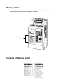
Warning Label
A warning label is attached to the product as shown in the following illustration. Be sure to
observe the precautionary items specified on the label.
Warning label
Contents of Warning Label
Read and Understand this Manual
Please read and understand this manual before using the product. Please consult your OMRON
representative if you have any questions or comments.
Warranty and Limitations of Liability
ÁÁÁÁÁÁÁÁÁÁÁÁÁÁÁÁÁÁÁÁÁÁÁÁÁÁÁÁÁÁÁÁÁ
WARRANTY
ÁÁÁÁÁÁÁÁÁÁÁÁÁÁÁÁÁÁÁÁÁÁÁÁÁÁÁÁÁÁÁÁÁ
ÁÁÁÁÁÁÁÁÁÁÁÁÁÁÁÁÁÁÁÁÁÁÁÁÁÁÁÁÁÁÁÁÁ
ÁÁÁÁÁÁÁÁÁÁÁÁÁÁÁÁÁÁÁÁÁÁÁÁÁÁÁÁÁÁÁÁÁ
ÁÁÁÁÁÁÁÁÁÁÁÁÁÁÁÁÁÁÁÁÁÁÁÁÁÁÁÁÁÁÁÁÁ
ÁÁÁÁÁÁÁÁÁÁÁÁÁÁÁÁÁÁÁÁÁÁÁÁÁÁÁÁÁÁÁÁÁ
ÁÁÁÁÁÁÁÁÁÁÁÁÁÁÁÁÁÁÁÁÁÁÁÁÁÁÁÁÁÁÁÁÁ
ÁÁÁÁÁÁÁÁÁÁÁÁÁÁÁÁÁÁÁÁÁÁÁÁÁÁÁÁÁÁÁÁÁ
ÁÁÁÁÁÁÁÁÁÁÁÁÁÁÁÁÁÁÁÁÁÁÁÁÁÁÁÁÁÁÁÁÁ
ÁÁÁÁÁÁÁÁÁÁÁÁÁÁÁÁÁÁÁÁÁÁÁÁÁÁÁÁÁÁÁÁÁ
LIMITATIONS OF LIABILITY
ÁÁÁÁÁÁÁÁÁÁÁÁÁÁÁÁÁÁÁÁÁÁÁÁÁÁÁÁÁÁÁÁÁ
ÁÁÁÁÁÁÁÁÁÁÁÁÁÁÁÁÁÁÁÁÁÁÁÁÁÁÁÁÁÁÁÁÁ
ÁÁÁÁÁÁÁÁÁÁÁÁÁÁÁÁÁÁÁÁÁÁÁÁÁÁÁÁÁÁÁÁÁ
ÁÁÁÁÁÁÁÁÁÁÁÁÁÁÁÁÁÁÁÁÁÁÁÁÁÁÁÁÁÁÁÁÁ
ÁÁÁÁÁÁÁÁÁÁÁÁÁÁÁÁÁÁÁÁÁÁÁÁÁÁÁÁÁÁÁÁÁ
ÁÁÁÁÁÁÁÁÁÁÁÁÁÁÁÁÁÁÁÁÁÁÁÁÁÁÁÁÁÁÁÁÁ
ÁÁÁÁÁÁÁÁÁÁÁÁÁÁÁÁÁÁÁÁÁÁÁÁÁÁÁÁÁÁÁÁÁ
ÁÁÁÁÁÁÁÁÁÁÁÁÁÁÁÁÁÁÁÁÁÁÁÁÁÁÁÁÁÁÁÁÁ
ÁÁÁÁÁÁÁÁÁÁÁÁÁÁÁÁÁÁÁÁÁÁÁÁÁÁÁÁÁÁÁÁÁ
ÁÁÁÁÁÁÁÁÁÁÁÁÁÁÁÁÁÁÁÁÁÁÁÁÁÁÁÁÁÁÁÁÁ
ÁÁÁÁÁÁÁÁÁÁÁÁÁÁÁÁÁÁÁÁÁÁÁÁÁÁÁÁÁÁÁÁÁ
OMRON’s exclusive warranty is that the products are free from defects in materials and workmanship for
a period of one year (or other period if specified) from date of sale by OMRON.
OMRON MAKES NO WARRANTY OR REPRESENTATION, EXPRESS OR IMPLIED, REGARDING
NON–INFRINGEMENT, MERCHANTABILITY, OR FITNESS FOR PARTICULAR PURPOSE OF THE
PRODUCTS. ANY BUYER OR USER ACKNOWLEDGES THAT THE BUYER OR USER ALONE HAS
DETERMINED THAT THE PRODUCTS WILL SUITABLY MEET THE REQUIREMENTS OF THEIR
INTENDED USE. OMRON DISCLAIMS ALL OTHER WARRANTIES, EXPRESS OR IMPLIED.
OMRON SHALL NOT BE RESPONSIBLE FOR SPECIAL, INDIRECT, OR CONSEQUENTIAL
DAMAGES, LOSS OF PROFITS OR COMMERCIAL LOSS IN ANY WAY CONNECTED WITH THE
PRODUCTS, WHETHER SUCH CLAIM IS BASED ON CONTRACT, WARRANTY, NEGLIGENCE, OR
STRICT LIABILITY.
In no event shall the responsibility of OMRON for any act exceed the individual price of the product on
which liability is asserted.
IN NO EVENT SHALL OMRON BE RESPONSIBLE FOR WARRANTY, REPAIR, OR OTHER CLAIMS
REGARDING THE PRODUCTS UNLESS OMRON’S ANALYSIS CONFIRMS THAT THE PRODUCTS
WERE PROPERLY HANDLED, STORED, INSTALLED, AND MAINTAINED AND NOT SUBJECT TO
CONTAMINATION, ABUSE, MISUSE, OR INAPPROPRIATE MODIFICATION OR REPAIR.
Application Considerations
ÁÁÁÁÁÁÁÁÁÁÁÁÁÁÁÁÁÁÁÁÁÁÁÁÁÁÁÁÁÁÁÁÁ
SUITABILITY FOR USE
ÁÁÁÁÁÁÁÁÁÁÁÁÁÁÁÁÁÁÁÁÁÁÁÁÁÁÁÁÁÁÁÁÁ
ÁÁÁÁÁÁÁÁÁÁÁÁÁÁÁÁÁÁÁÁÁÁÁÁÁÁÁÁÁÁÁÁÁ
ÁÁÁÁÁÁÁÁÁÁÁÁÁÁÁÁÁÁÁÁÁÁÁÁÁÁÁÁÁÁÁÁÁ
ÁÁÁÁÁÁÁÁÁÁÁÁÁÁÁÁÁÁÁÁÁÁÁÁÁÁÁÁÁÁÁÁÁ
ÁÁÁÁÁÁÁÁÁÁÁÁÁÁÁÁÁÁÁÁÁÁÁÁÁÁÁÁÁÁÁÁÁ
ÁÁÁÁÁÁÁÁÁÁÁÁÁÁÁÁÁÁÁÁÁÁÁÁÁÁÁÁÁÁÁÁÁ
ÁÁÁÁÁÁÁÁÁÁÁÁÁÁÁÁÁÁÁÁÁÁÁÁÁÁÁÁÁÁÁÁÁ
ÁÁÁÁÁÁÁÁÁÁÁÁÁÁÁÁÁÁÁÁÁÁÁÁÁÁÁÁÁÁÁÁÁ
ÁÁÁÁÁÁÁÁÁÁÁÁÁÁÁÁÁÁÁÁÁÁÁÁÁÁÁÁÁÁÁÁÁ
ÁÁÁÁÁÁÁÁÁÁÁÁÁÁÁÁÁÁÁÁÁÁÁÁÁÁÁÁÁÁÁÁÁ
ÁÁÁÁÁÁÁÁÁÁÁÁÁÁÁÁÁÁÁÁÁÁÁÁÁÁÁÁÁÁÁÁÁ
ÁÁÁÁÁÁÁÁÁÁÁÁÁÁÁÁÁÁÁÁÁÁÁÁÁÁÁÁÁÁÁÁÁ
ÁÁÁÁÁÁÁÁÁÁÁÁÁÁÁÁÁÁÁÁÁÁÁÁÁÁÁÁÁÁÁÁÁ
ÁÁÁÁÁÁÁÁÁÁÁÁÁÁÁÁÁÁÁÁÁÁÁÁÁÁÁÁÁÁÁÁÁ
ÁÁÁÁÁÁÁÁÁÁÁÁÁÁÁÁÁÁÁÁÁÁÁÁÁÁÁÁÁÁÁÁÁ
ÁÁÁÁÁÁÁÁÁÁÁÁÁÁÁÁÁÁÁÁÁÁÁÁÁÁÁÁÁÁÁÁÁ
ÁÁÁÁÁÁÁÁÁÁÁÁÁÁÁÁÁÁÁÁÁÁÁÁÁÁÁÁÁÁÁÁÁ
ÁÁÁÁÁÁÁÁÁÁÁÁÁÁÁÁÁÁÁÁÁÁÁÁÁÁÁÁÁÁÁÁÁ
ÁÁÁÁÁÁÁÁÁÁÁÁÁÁÁÁÁÁÁÁÁÁÁÁÁÁÁÁÁÁÁÁÁ
ÁÁÁÁÁÁÁÁÁÁÁÁÁÁÁÁÁÁÁÁÁÁÁÁÁÁÁÁÁÁÁÁÁ
ÁÁÁÁÁÁÁÁÁÁÁÁÁÁÁÁÁÁÁÁÁÁÁÁÁÁÁÁÁÁÁÁÁ
ÁÁÁÁÁÁÁÁÁÁÁÁÁÁÁÁÁÁÁÁÁÁÁÁÁÁÁÁÁÁÁÁÁ
ÁÁÁÁÁÁÁÁÁÁÁÁÁÁÁÁÁÁÁÁÁÁÁÁÁÁÁÁÁÁÁÁÁ
ÁÁÁÁÁÁÁÁÁÁÁÁÁÁÁÁÁÁÁÁÁÁÁÁÁÁÁÁÁÁÁÁÁ
PROGRAMMABLE PRODUCTS
ÁÁÁÁÁÁÁÁÁÁÁÁÁÁÁÁÁÁÁÁÁÁÁÁÁÁÁÁÁÁÁÁÁ
ÁÁÁÁÁÁÁÁÁÁÁÁÁÁÁÁÁÁÁÁÁÁÁÁÁÁÁÁÁÁÁÁÁ
ÁÁÁÁÁÁÁÁÁÁÁÁÁÁÁÁÁÁÁÁÁÁÁÁÁÁÁÁÁÁÁÁÁ
OMRON shall not be responsible for conformity with any standards, codes, or regulations that apply to
the combination of products in the customer’s application or use of the products.
At the customer’s request, OMRON will provide applicable third party certification documents identifying
ratings and limitations of use that apply to the products. This information by itself is not sufficient for a
complete determination of the suitability of the products in combination with the end product, machine,
system, or other application or use.
The following are some examples of applications for which particular attention must be given. This is not
intended to be an exhaustive list of all possible uses of the products, nor is it intended to imply that the
uses listed may be suitable for the products:
• Outdoor use, uses involving potential chemical contamination or electrical interference, or conditions
or uses not described in this manual.
• Nuclear energy control systems, combustion systems, railroad systems, aviation systems, medical
equipment, amusement machines, vehicles, safety equipment, and installations subject to separate
industry or government regulations.
• Systems, machines, and equipment that could present a risk to life or property.
Please know and observe all prohibitions of use applicable to the products.
NEVER USE THE PRODUCTS FOR AN APPLICATION INVOLVING SERIOUS RISK TO LIFE OR
PROPERTY WITHOUT ENSURING THAT THE SYSTEM AS A WHOLE HAS BEEN DESIGNED TO
ADDRESS THE RISKS, AND THAT THE OMRON PRODUCTS ARE PROPERLY RATED AND
INSTALLED FOR THE INTENDED USE WITHIN THE OVERALL EQUIPMENT OR SYSTEM.
OMRON shall not be responsible for the user’s programming of a programmable product, or any
consequence thereof.
Disclaimers
ÁÁÁÁÁÁÁÁÁÁÁÁÁÁÁÁÁÁÁÁÁÁÁÁÁÁÁÁÁÁÁÁÁ
CHANGE IN SPECIFICATIONS
ÁÁÁÁÁÁÁÁÁÁÁÁÁÁÁÁÁÁÁÁÁÁÁÁÁÁÁÁÁÁÁÁÁ
ÁÁÁÁÁÁÁÁÁÁÁÁÁÁÁÁÁÁÁÁÁÁÁÁÁÁÁÁÁÁÁÁÁ
ÁÁÁÁÁÁÁÁÁÁÁÁÁÁÁÁÁÁÁÁÁÁÁÁÁÁÁÁÁÁÁÁÁ
ÁÁÁÁÁÁÁÁÁÁÁÁÁÁÁÁÁÁÁÁÁÁÁÁÁÁÁÁÁÁÁÁÁ
ÁÁÁÁÁÁÁÁÁÁÁÁÁÁÁÁÁÁÁÁÁÁÁÁÁÁÁÁÁÁÁÁÁ
ÁÁÁÁÁÁÁÁÁÁÁÁÁÁÁÁÁÁÁÁÁÁÁÁÁÁÁÁÁÁÁÁÁ
ÁÁÁÁÁÁÁÁÁÁÁÁÁÁÁÁÁÁÁÁÁÁÁÁÁÁÁÁÁÁÁÁÁ
ÁÁÁÁÁÁÁÁÁÁÁÁÁÁÁÁÁÁÁÁÁÁÁÁÁÁÁÁÁÁÁÁÁ
ÁÁÁÁÁÁÁÁÁÁÁÁÁÁÁÁÁÁÁÁÁÁÁÁÁÁÁÁÁÁÁÁÁ
DIMENSIONS AND WEIGHTS
ÁÁÁÁÁÁÁÁÁÁÁÁÁÁÁÁÁÁÁÁÁÁÁÁÁÁÁÁÁÁÁÁÁ
ÁÁÁÁÁÁÁÁÁÁÁÁÁÁÁÁÁÁÁÁÁÁÁÁÁÁÁÁÁÁÁÁÁ
ÁÁÁÁÁÁÁÁÁÁÁÁÁÁÁÁÁÁÁÁÁÁÁÁÁÁÁÁÁÁÁÁÁ
ÁÁÁÁÁÁÁÁÁÁÁÁÁÁÁÁÁÁÁÁÁÁÁÁÁÁÁÁÁÁÁÁÁ
ÁÁÁÁÁÁÁÁÁÁÁÁÁÁÁÁÁÁÁÁÁÁÁÁÁÁÁÁÁÁÁÁÁ
PERFORMANCE DATA
ÁÁÁÁÁÁÁÁÁÁÁÁÁÁÁÁÁÁÁÁÁÁÁÁÁÁÁÁÁÁÁÁÁ
ÁÁÁÁÁÁÁÁÁÁÁÁÁÁÁÁÁÁÁÁÁÁÁÁÁÁÁÁÁÁÁÁÁ
ÁÁÁÁÁÁÁÁÁÁÁÁÁÁÁÁÁÁÁÁÁÁÁÁÁÁÁÁÁÁÁÁÁ
ÁÁÁÁÁÁÁÁÁÁÁÁÁÁÁÁÁÁÁÁÁÁÁÁÁÁÁÁÁÁÁÁÁ
ÁÁÁÁÁÁÁÁÁÁÁÁÁÁÁÁÁÁÁÁÁÁÁÁÁÁÁÁÁÁÁÁÁ
ÁÁÁÁÁÁÁÁÁÁÁÁÁÁÁÁÁÁÁÁÁÁÁÁÁÁÁÁÁÁÁÁÁ
ERRORS AND OMISSIONS
ÁÁÁÁÁÁÁÁÁÁÁÁÁÁÁÁÁÁÁÁÁÁÁÁÁÁÁÁÁÁÁÁÁ
ÁÁÁÁÁÁÁÁÁÁÁÁÁÁÁÁÁÁÁÁÁÁÁÁÁÁÁÁÁÁÁÁÁ
ÁÁÁÁÁÁÁÁÁÁÁÁÁÁÁÁÁÁÁÁÁÁÁÁÁÁÁÁÁÁÁÁÁ
ÁÁÁÁÁÁÁÁÁÁÁÁÁÁÁÁÁÁÁÁÁÁÁÁÁÁÁÁÁÁÁÁÁ
Product specifications and accessories may be changed at any time based on improvements and other
reasons.
It is our practice to change model numbers when published ratings or features are changed, or when
significant construction changes are made. However, some specifications of the products may be
changed without any notice. When in doubt, special model numbers may be assigned to fix or establish
key specifications for your application on your request. Please consult with your OMRON representative
at any time to confirm actual specifications of purchased products.
Dimensions and weights are nominal and are not to be used for manufacturing purposes, even when
tolerances are shown.
Performance data given in this manual is provided as a guide for the user in determining suitability and
does not constitute a warranty. It may represent the result of OMRON’s test conditions, and the users
must correlate it to actual application requirements. Actual performance is subject to the OMRON
Warranty and Limitations of Liability.
The information in this manual has been carefully checked and is believed to be accurate; however, no
responsibility is assumed for clerical, typographical, or proofreading errors, or omissions.
Table of Contents
Chapter 1. Getting Started . . . . . . . . . . . . . . . . . . . . . . . . . . . . . . . . . . . 1-1
1-1 Items to be Checked when Unpacking . . . . . . . . . . . . . . . . . . . . . . . . . . . . . . . . . . . . . . . . . . .
1-2 Precautions . . . . . . . . . . . . . . . . . . . . . . . . . . . . . . . . . . . . . . . . . . . . . . . . . . . . . . . . . . . . . . . . .
1-2
1-3
Chapter 2. Overview . . . . . . . . . . . . . . . . . . . . . . . . . . . . . . . . . . . . . . . . 2-1
2-1 Features . . . . . . . . . . . . . . . . . . . . . . . . . . . . . . . . . . . . . . . . . . . . . . . . . . . . . . . . . . . . . . . . . . .
2-2 Nomenclature . . . . . . . . . . . . . . . . . . . . . . . . . . . . . . . . . . . . . . . . . . . . . . . . . . . . . . . . . . . . . . .
2-2
2-4
Chapter 3. Design . . . . . . . . . . . . . . . . . . . . . . . . . . . . . . . . . . . . . . . . . . 3-1
3-1 Installation . . . . . . . . . . . . . . . . . . . . . . . . . . . . . . . . . . . . . . . . . . . . . . . . . . . . . . . . . . . . . . . . . 3-2
3-1-1 Outside/Mounting Dimensions . . . . . . . . . . . . . . . . . . . . . . . . . . . . . . . . . . . . . . . . . . . 3-2
3-1-2 Installation Conditions . . . . . . . . . . . . . . . . . . . . . . . . . . . . . . . . . . . . . . . . . . . . . . . . . 3-4
3-2 Wiring . . . . . . . . . . . . . . . . . . . . . . . . . . . . . . . . . . . . . . . . . . . . . . . . . . . . . . . . . . . . . . . . . . . . 3-6
3-2-1 Terminal Blocks . . . . . . . . . . . . . . . . . . . . . . . . . . . . . . . . . . . . . . . . . . . . . . . . . . . . . . 3-7
3-2-2 Wiring Around the Main Circuit . . . . . . . . . . . . . . . . . . . . . . . . . . . . . . . . . . . . . . . . . 3-11
3-2-3 Wiring Control Circuit Terminals . . . . . . . . . . . . . . . . . . . . . . . . . . . . . . . . . . . . . . . . . 3-19
Chapter 4. Specifications . . . . . . . . . . . . . . . . . . . . . . . . . . . . . . . . . . . . 4-1
4-1 Specifications of Main Unit . . . . . . . . . . . . . . . . . . . . . . . . . . . . . . . . . . . . . . . . . . . . . . . . . . . .
4-2 Specifications of Noise Filter . . . . . . . . . . . . . . . . . . . . . . . . . . . . . . . . . . . . . . . . . . . . . . . . . .
Index . . . . . . . . . . . . . . . . . . . . . . . . . . . . . . . . . . . . . . . . . .
Revision History . . . . . . . . . . . . . . . . . . . . . . . . . . . . . . . . .
4-2
4-6
I-1
R-1
1
Chapter 1
Getting Started
1-1
1-2
Items to be Checked when Unpacking
Precautions
Chapter 1
Getting Started
1-1
Items to be Checked when Unpacking
H Checking the Product
On delivery, always check that the delivered product is the SYSDRIVE 3G3EV Inverter that you ordered.
Should you find any problems with the product, immediately contact your nearest local sales representative.
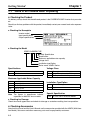
D Checking the Nameplate
Inverter model
Input specifications
Output specifications
D Checking the Model
3G3EV-A4002M-CUE
Special Specification
Specification
Maximum applicable motor capacity
Voltage class
Installation type/Option
Series name: 3G3EV Series
Specifications
Blank
M
Standard model
Multi-function model
Voltage Class
2
B
4
Three-phase 200-VAC input
Single/Three-phase 200-VAC input
Three-phase 400-VAC input
Maximum Applicable Motor Capacity
001
002
004
007
015
Note
0.1 kW
0.2 (0.37) kW
0.4 (0.55) kW
0.75 (1.1) kW
1.5 kW
The figures in parentheses indicate
capacities for 400-VAC class models.
Installation Type/Option
A
P
Panel mounting
Option
Special Specification
-CUE
UL/CUL and EC Directives Models
D Checking for Damage
Check the overall appearance and check for damage or scratches resulting from transportation.
H Checking Accessories
Note that this manual and the User’s Manual are the accessories provided with the 3G3EV (Multi-function Model). Set screws and other necessary parts must be prepared by customers.
1-2
Chapter 1
Getting Started
1-2
Precautions
To ensure safe operation of the 3G3EV, note the following items:
H Always Hold the Heat Sink During Removal
When moving the 3G3EV, always hold the heat sink (aluminum portion on the rear of the Unit).
Heat sink
H Watch Out for Residual Voltage On Charged Portions
After the power is turned off, residual voltage remains in the capacitor inside the Inverter. Therefore,
touching terminals immediately after turning the power off may cause an electrical shock.
If an inspection or some other task is to be performed, always wait at least one minute from the time all
indicators on the front panel go off.
(Note that this warning is applicable whenever you perform any task after turning the main circuit off.)
H Do Not Remove the Digital Operator When the Main Circuit is Still On.
Always turn the main circuit off before removing the Digital Operator.
Removing the Digital Operator with the main circuit ON may cause an electrical shock and damage the
equipment.
H Do Not Modify Wiring or Check Signals When the Main Circuit is ON
Always turn the main circuit off before modifying wiring or checking signals.
Touching terminals while the main circuit is on may cause an electrical shock and damage the equipment.
H Do Not Conduct a Dielectric Strength Test
Because the 3G3EV Inverter is an electronic control unit using semiconductor, never conduct a dielectric strength test or an insulation resistance test for the control circuit.
H Modify Constant Settings Correctly
Always modify the constant settings according to the procedures described in this manual and the
User’s Manual.
1-3
2
Chapter 2
Overview
2-1
2-2
Features
Nomenclature
Chapter 2
Overview
2-1
Features
H 3G3EV-series Models (EC Directives Models)
Standard and multi-function 3G3EV-series Inverters of EC Directives Models are available.
The maximum applicable motor capacities for the 200-VAC class are 0.1 to 1.5 kW (5 models) and 0.2 to
1.5 kW (4 models) for the 400-VAC class.
Type
Standard
Multi-function
Note
2-2
Voltage class
200-VAC input
p
(h
(three-phase)
h
)
Enclosure
rating
Enclosed panel
p
mounted
d
200-VAC input
p
( i l /h
(single/threephase)
Enclosed panel
p
mounted
d
400-VAC input
p
(h
(three-phase)
h
)
Enclosed panel
p
mounted
d
200-VAC input
p
(h
(three-phase)
h
)
Enclosed panel
p
mounted
d
200-VAC input
p
( i l /h
(single/threephase)
Enclosed panel
p
mounted
d
400-VAC input
p
(h
(three-phase)
h
)
Enclosed panel
p
mounted
d
Max. applicable motor
capacity
0.1 kW
0.2 kW
0.4 kW
0.75 kW
1.5 kW
0.1 kW
0.2 kW
0.4 kW
0.75 kW
1.5 kW
0.2 (0.37) kW
0.4 (0.55) kW
0.75 (1.1) kW
1.5 kW
0.1 kW
0.2 kW
0.4 kW
0.75 kW
1.5 kW
0.1 kW
0.2 kW
0.4 kW
0.75 kW
1.5 kW
0.2 (0.37) kW
0.4 (0.55) kW
0.75 (1.1) kW
1.5 kW
Model
3G3EV-A2001-CUE
3G3EV-A2002-CUE
3G3EV-A2004-CUE
3G3EV-A2007-CUE
3G3EV-A2015-CUE
3G3EV-AB001-CUE
3G3EV-AB002-CUE
3G3EV-AB004-CUE
3G3EV-AB007-CUE
3G3EV-AB015-CUE
3G3EV-A4002-CUE
3G3EV-A4004-CUE
3G3EV-A4007-CUE
3G3EV-A4015-CUE
3G3EV-A2001M-CUE
3G3EV-A2002M-CUE
3G3EV-A2004M-CUE
3G3EV-A2007M-CUE
3G3EV-A2015M-CUE
3G3EV-AB001M-CUE
3G3EV-AB002M-CUE
3G3EV-AB004M-CUE
3G3EV-AB007M-CUE
3G3EV-AB015M-CUE
3G3EV-A4002M-CUE
3G3EV-A4004M-CUE
3G3EV-A4007M-CUE
3G3EV-A4015M-CUE
Model numbers with a suffix of “-CUE” indicate models approved by UL. (Approval has not been
obtained for models with a model number suffix of “-CE.”)
Overview
Chapter 2
H LVD and EMC Directives
The SYSDRIVE EC Directives Models conform to the LVD (prEN50178) and the EMC (EN50081-2,
EN50082-2) Directives.
However, when the product is built into a unit, the connected switches, optional items, or motors may not
satisfy these Directives. In such a case, either use components that meet the Directives or take appropriate countermeasures such as providing surge killers or other noise prevention devices.
H Required Conditions
There are several conditions that must be satisfied for this Inverter to conform to the LVD and EMC
Directives. To satisfy the Directives, meet the instructions in this manual for the following installation
conditions.
• Installation of noise filters and clamp core.
• Shield braided cables must be used for input and output cables.
Limitations on the lengths of cables.
• Installation of recommended fuses on the input side.
H Other Functions
This manual describes installation and wiring methods for conforming to the LVD and EMC Directives.
Refer to the User’s Manual for detailed information on the functions of the Inverter.
• 3G3EV-series Standard Model:
SYSDRIVE 3G3EV Compact Low-noise Inverter (I011-E1)
• 3G3EV-series Multi-function Model:
SYSDRIVE 3G3EV Compact Low-noise Inverter (I013-E1)
2-3
Chapter 2
Overview
2-2
Nomenclature
H Main Unit
Main Circuit Terminals (Input)
Power input
terminals
Braking resistor
connection terminals
L1 N/L2 L3
B1 B2
Digital Operator
Run indicator
Alarm indicator
Control circuit terminals
(input/output)
Control circuit terminals (output)
S2 S3 SC AM AC PA PC
MA MB MC
SF SR S1 SC FS FR FC
U
V
W
Ground terminal
Motor output
terminals
Main Circuit Terminals (Output)
Note
This diagram shows the Inverter with all terminal block covers removed.
The standard Inverters are not provided with the upper terminal block (S2 to PC).
2-4
Chapter 2
Overview
H Digital Operator
Data display section
Monitor item indicators
Display
section
In-service item indicators (green indicators)
These items can be monitored or set even
during operation.
Stopped item indicators (red indicators)
These items can be set only when the
Inverter is stopped.
Operation keys
Constant item indicators
Mode Key
Increment Key
RUN Key
Enter Key
Decrement Key
STOP/RESET Key
2-5
3
Chapter 3
Design
3-1
3-2
Installation
Wiring
Chapter 3
Design
3-1
Installation
3-1-1 Outside/Mounting Dimensions
Note
All dimensions are in millimeters.
H 3G3EV-A2001(M)-CUE to 3G3EV-A2004(M)-CUE (0.1 to 0.4 kW):
Three-phase 200-VAC Input
H 3G3EV-AB001(M)-CUE to 3G3EV-AB002(M)-CUE (0.1 to 0.2 kW):
Single/Three-phase 200-VAC Input
4.5 dia.
Note 1. For the 3G3EV-A2001(M)-CUE, 3G3EV-A2002(M)-CUE, and 3G3EV-AB001(M)-CUE, a Ushaped notch (4.5 mm wide) is provided instead of the upper mounting hole (4.5 mm in diameter).
Note 2. Install the Inverter with two M4 bolts.
D Three-phase 200-VAC Input Model
3G3EV model
Output
W
68
H
128
D
56
H1
118
T
A2001(M)-CUE
0.1 kW
A2002(M)-CUE
0.2 kW
88
3
A2004(M)-CUE
0.4 kW
110
5
3-2
75
W1
3
Weight
(kg)
Approx.
0.5
Approx.
0.6
Approx.
0.9
Chapter 3
Design
D Single/Three-phase 200-VAC Input Model
3G3EV model
Output
AB001(M)-CUE
0.1 kW
AB002(M)-CUE
0.2 kW
W
H
68
D
128
W1
56
75
H1
118
108
T
3
3
Weight
(kg)
Approx.
0.5
Approx.
0.6
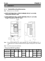
H 3G3EV-A2007(M)-CUE to 3G3EV-A2015(M)-CUE (0.75 to 1.5 kW):
Three-phase 200-VAC Input
3G3EV-AB004(M)-CUE to 3G3EV-AB015(M)-CUE (0.4 to 1.5 kW):
Single/Three-phase 200-VAC Input
3G3EV-A4002(M)-CUE to 3G3EV-A4015(M)-CUE (0.2 to 1.5 kW):
Three-phase 400-VAC Input
Two, 4.5 dia.
Note
Install the Inverter with four M4 bolts.
D Three-phase 200-VAC Input Model
3G3EV model
A2007(M)-CUE
A2015(M)-CUE
Output
0.75 kW
1.5 kW
W
108
H
128
D
W1
96
130
155
H1
Weight (kg)
Approx. 1.3
Approx. 1.5
H1
Weight (kg)
Approx. 1.3
Approx. 1.3
Approx. 2.0
118
D Single/Three-phase 200-VAC Input Model
3G3EV model
AB004(M)-CUE
AB007(M)-CUE
AB015(M)-CUE
Output
0.4 kW
0.75 kW
1.5 kW
W
108
130
H
128
D
W1
130
96
170
118
118
3-3
Chapter 3
Design
D Three-phase 400-VAC Input Model
3G3EV model
A4002(M)-CUE
A4004(M)-CUE
A4007(M)-CUE
A4015(M)-CUE
Output
0.2 kW
0.4 kW
0.75 kW
1.5 kW
W
H
108
128
D
92
110
140
170
130
W1
H1
96
118
118
Weight (kg)
Approx. 1.0
Approx. 1.0
Approx. 1.5
Approx. 2.0
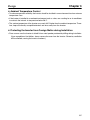
3-1-2 Installation Conditions
H Installation Site
• Install the Inverter under the following conditions:
Ambient temperature for operation: –10°C to 50°C
Humidity: 90% RH or less (non-condensing)
• Install the Inverter in a clean location free from oil mist and dust. Alternatively, install it in a totally enclosed panel that is completely shielded from suspended dust.
• When installing or operating the Inverter, always take special care so that metal powder, oil, water, or
other foreign matter do not get in the Inverter.
• Do not install the Inverter on inflammables such as wood.
H Direction of Installation
• Install the Inverter on a vertical surface so that the characters on the nameplate are oriented upward.
H Installation Space
• When installing the Inverter, always provide the following installation space to allow normal heat dissipation from the Inverter:
100 mm min.
Inverter
Inverter
Inverter
W= 30 mm min.
Side
100 mm min.
3-4
Air
Air
Design
Chapter 3
H Ambient Temperature Control
• To enhance operation reliability, the Inverter should be installed in an environment free from extreme
temperature rises.
• If the Inverter is installed in an enclosed environment such as a box, use a cooling fan or air conditioner
to maintain the internal air temperature below 50°C.
• The surface temperature of the Inverter may reach 30°C higher than the ambient temperature. Therefore, keep all thermally susceptible devices and wires away from the Inverter.
H Protecting the Inverter from Foreign Matter during Installation
• Place a cover over the Inverter to shield it from metal powder produced by drilling during installation.
(Upon completion of installation, always remove the cover from the Inverter. Otherwise, ventilation
will be affected, causing the invert to overheat.)
3-5
Chapter 3
Design
3-2
Wiring
H Cautions and Warnings
! WARNING
Be sure that the power supply is turned OFF before wiring. Wait for at least one
minute after turning off the power supply. Otherwise, an electric shock may occur.
! WARNING
Wiring must be performed by authorized persons specialized in electrical work.
Otherwise, an electric shock or fire may occur.
! WARNING
Be sure to check for proper operation after wiring the emergency stop circuit.
Otherwise, physical injury may occur.
! WARNING
Be sure to ground the ground terminal. Otherwise, an electric shock or fire may
occur.
! WARNING
Be sure to connect the ground to the supply neutral for 400-VAC-class Inverters.
Otherwise, an electric shock or equipment damage may occur.
! WARNING
Be sure to confirm that the rated voltage of the Inverter coincides with the voltage
of the AC power supply. Otherwise, a fire, injury, or equipment trouble may occur.
! WARNING
When connecting the braking resistor or Braking Resistor Unit, be sure to follow
the instructions specified in the Installation Manual. Otherwise, a fire may occur.
! WARNING
Be sure to wire correctly. Otherwise, injury or equipment damage may occur.
! WARNING
Be sure to firmly tighten the screws on the terminal block. Otherwise, a fire, injury, or equipment damage may occur.
! Caution
3-6
Do not connect the AC power to the output terminal U, V, or W. Otherwise, equipment damage or trouble may occur.
Chapter 3
Design
3-2-1 Terminal Blocks
H Name of Each Terminal Block
Main Circuit Terminals (Input)
Power input
Braking resistor
terminals
connection terminals
L1 N/L2 L3
B1 B2
Control circuit terminals
(input/output)
Control circuit terminals (output)
S2 S3 SC AM AC PA PC
MA MB MC
SF SR S1 SC FS FR FC
U
Ground terminal
V
W
Motor output
terminals
Main Circuit Terminals (Output)
Note
This diagram shows an Inverter with all terminal block covers removed.
The standard Inverters are not provided with the S2 to PC terminal block.
3-7
Chapter 3
Design
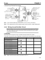
H Main Circuit Terminals
D Input Terminals (Top Section)
Terminal
symbol
L1
N/L2
L3
Name and description
Power input terminals
AB:
A4:
Note: Single-phase power must be input between terminals L1 to N/L2
Braking resistor connection terminals (see note)
B1
B2
Note
Single-phase 200 to 240 VAC, 50/60 Hz
Three-phase 200 to 230 VAC, 50/60 Hz
Three-phase 380 to 460 VAC, 50/60 Hz
Terminals for connecting an optional braking resistor
Before shipping, a resin plate is attached to each braking resistor connection terminal to prevent
incorrect wiring.
When connecting a braking resistor, always remove the resin plates with a pair of long-nose
pliers.
D Output Terminals (Bottom Section)
Terminal
symbol
U
V
W
Name and description
Motor output terminals
Three-phase power output terminals for operating the motor. (Never connect an AC power
supply to these terminals.)
ABj: Three-phase 200 to 230 VAC
A4j: Three-phase 380 to 460 VAC
Note: Depends on the input voltage.
Ground terminal
Always use a grounding terminal with a ground resistance of followings,
100 Ω or less of 200-VAC class
10 Ω or less of 400-VAC class
(Connect also to the power supply neutral to conform to the EC Directives.)
Be sure to connect a grounding line to the FG terminal and also connect directly to the FG
terminal of the motor.
Terminal block screw (M3.5)
Crimp terminal
6.2 mm max.
3-8
Chapter 3
Design
H Control Circuit Terminals
D Input Terminals (On Right-hand Side)
No external power supply is required because a built-in power supply is provided.
Terminal
symbol
SF
Name and description
Forward/Stop (see note 3)
SR
The motor will rotate in the forward direction when the
signal on this terminal is turned ON. The motor will stop
rotating when the signal is turned OFF.
Reverse/Stop (see note 3)
S1 to S3
SC
The motor will rotate in the reversed direction when the
signal on this terminal is turned ON. The motor will stop
rotating when the signal is turned OFF.
Multi-function input (see notes 1, 3)
Sequence input common
FS
Input terminal common for SF to S3
Frequency reference power supply
24 V
Output voltage: 12 VDC
Permissible current: 20 mA
FR
Interface
3.3 K
S1 to S3
0.1 µ
12 V
20 K
Frequency reference input (see note 2)
0 to 10 VDC
FC
Input impedance
Frequency reference common
20 kΩ
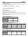
Note 1. Functions are set with constants n06 to n08. Only n06: S1 is, however, available to the standard model.
Refer to the following for factory settings:
S1: Fault reset
(n06=1)
S2: External fault (input to contact a) (n07=2)
S3: Multi-step speed command
(n08=4)
Note 2. The FR terminal will function as a 4- to 20-mA input terminal with the setting of the internal
switch 1 (SW1) and n02 for operation mode selection.
Note 3. The sequential input method will change with the setting of the internal switch 2 (SW2).
D Output Terminals (On Left-hand Side)
Terminal
symbol
MA
Multi-function contact output (contact a) (see note)
MB
Multi-function contact output (contact b) (see note)
MC
Multi-function contact output (common)
Note
Name and description
Interface
30 VDC
250 VAC
Constant No. 09 (n09) is used to set the function. This constant is factory set to “during running.”
3-9
Chapter 3
Design
D Output Terminals (On Right-hand Side)
Terminal
symbol
PA
Name and description
Multi-function photocoupler output (see note)
PC
Multi-function photocoupler output (common)
Interface
50 mA at 48 VDC max.
Note
Constant No. 10 (n10) is used to set this function. This constant is factory-set to “fault.”
The standard model does not have multi-function photocoupler output.
D Analog Output Terminals (On Right-hand Side)
Terminal
symbol
AM
Name and description
Multi-function analog output (see note)
AC
Multi-function analog output (common)
Interface
2 mA at
0 to +10 VDC max.
Note
Constant No. 44 (n44) is used to set this function and constant No. 45 (n45) is used to set the
multiplying factor, which are factory-set to “output frequency” and “3V at maximum frequency”
respectively.
The standard model does not have analog output.
H Standard Connection Diagram
D Main Circuit Terminal Connections
Three-phase,
200 VAC
Single-phase,
200 VAC
Three-phase,
400 VAC
Circuit
breaker Noise Filter
Braking Unit (Optional)
Note 1. Three-phase 200 VAC (400 VAC) can be input to L1, L2, and L3.
Note 2. For the 400-VAC-class Inverter, be sure to ground the supply neutral.
3-10
Clamp core
Chapter 3
Design
D Control Circuit Terminal Connections
Multi-function contact
output (Contact a)
(Contact b)
Forward/Stop
Clamp core
Reverse/Stop
Common
S1 to S3
Multi-function input
Sequence input common
Multi-function
photocoupler output
Multi-function
photocoupler output
common
Multi-function analog output
Voltmeter
Clamp
core
Frequency reference adjuster
Frequency reference
power supply (12 V)
Frequency reference
input
Frequency reference
input common
(2 kΩ, 1/4 W min.)
Multi-function analog
output common
Note 1. The standard model does not have the S2, S3, PA, PC, AM, or AC terminal.
Note 2. The sequence input and the sequence output can be wired with a single shielded cable.
3-2-2 Wiring Around the Main Circuit
System reliability and noise resistance are affected by the wiring method used. Therefore, always follow the instructions given below when connecting the Inverter to peripheral devices and other parts.
H Wire Size
For the main circuit and ground, always use 600-V polyvinyl chloride (PVC) cables.
If the cable is long and may cause voltage drops, increase the wire size according to the cable length.
Model
3G3EV-A2001(M)-CUE
Terminal symbol
R S T B1 B2
3G3EV-AB001(M)-CUE
UVW
3G3EV-A2002(M)-CUE
3G3EV-AB002(M)-CUE
3G3EV-A4002(M)-CUE
3G3EV-A2004(M)-CUE
3G3EV-AB004(M)-CUE
3G3EV-A4004(M)-CUE
3G3EV-A2007(M)-CUE
3G3EV-AB007(M)-CUE
3G3EV-A4007(M)-CUE
3G3EV-A2015(M)-CUE
3G3EV-AB015(M)-CUE
3G3EV-A4015(M)-CUE
R S T B1 B2
Note
Terminal screw
M3.5
Wire size (mm2)
0.75 to 2
M3.5
0.75 to 2
M3.5
0.75 to 2
M3.5
0.75 to 2
M3.5
1.25 to 2
UVW
R S T B1 B2
UVW
R S T B1 B2
UVW
R S T B1 B2
UVW
0.75 to 2
Tighten the M3.5 terminal screw to the torque of 0.8 N S m.
3-11
Chapter 3
Design
Determining the Wire Size
Determine the wire size for the main circuit so that line voltage drop is within 2% of the rated voltage.
Line voltage drop VD is calculated as follows:
VD (V) = Ǹ3 x wire resistance (Ω/km) x wire length (m) x amperage (A) x 10–3
H Conformance to EMC Directives
D Wiring Power Supply
Install the Inverter and Noise Filter on ground plates.
Be sure to wire the Inverter through a dedicated Noise Filter.
Reduce the length of the ground wire as much as possible and connect the ground wire to the ground
securely.
Reduce length of the cable between the Inverter and the Noise Filter as much as possible. The cable
length must not exceed 400 mm.
Three-phase 200-VAC Noise Filter
Inverter
Model 3G3EVA2001(M)-CUE
A2002(M)-CUE
A2004(M)-CUE
A2007(M)-CUE
A2015(M)-CUE
Single-phase Noise Filter (Soshin Electric)
Model 3G3EVRated current (A)
PNF3006A-YN
6
PNF3010A-YN
10
Single-phase 200-VAC Noise Filter
Inverter
Model 3G3EVAB001(M)-CUE
AB002(M)-CUE
AB004(M)-CUE
AB007(M)-CUE
AB015(M)-CUE
Model 3G3EVPNF2003A-YN
Single-phase Noise Filter (Soshin Electric)
Rated current (A)
Weight (kg)
Dimensions
3
Approx.
pp
0.5
66 × 117 × 67
PNF2010A-YN
10
Approx.
pp
0.6
66 × 117 × 67
PNF2020A-YN
20
Approx. 1.0
74 × 128 × 72
Single-phase 200-VAC Noise Filter
Inverter
Model 3G3EVA4002(M)-CUE
A4004(M)-CUE
A4007(M)-CUE
A4015(M)-CUE
3-12
Model 3G3EVPNF3007C-YN
Single-phase Noise Filter (Soshin Electric)
Rated current (A)
Weight (kg)
Dimensions
7
Approx.
1.0
108 × 128 × 75
pp
Chapter 3
Design
D Wiring between Inverter and Motor
Be sure to use a shield braided cable to connect the Inverter and motor.
Reduce the length of the cable as much as possible and ground the shield on the Inverter side and motor
side. The cable length must not exceed 20 m. Furthermore, attach a clamp core close to the Inverter’s
output terminals and the shield of the Inverter side.
Recommended Clamp Core
Product name
Clamp filter
Model
ZCAT3035-1330
Manufacturer
TDK
D Wiring Control Circuit Cable
Be sure to use a shield braided cable for the control circuit and ground the shield on the inverter side at
one point. Further more, attach a clamp core close to the Inverter.
Braking Unit (Optional)
Circuit
breaker Noise Filter
Three-phase,
200 VAC
Single-phase,
200 VAC
Three-phase,
400-VAC
Note
Clamp core
For the 400-VAC-class Inverter, be sure to ground the supply neutral.
D Grounding the Braided Shield
It is recommended that a cable clamp be attached to the braided shield for grounding, which allows the
secure grounding of the braided shield.
Cable clamp
Ground plate
Cable
Shield
3-13
Chapter 3
Design
H Conformance to LVD
Be sure to insert a molded-case circuit breaker (MCCB) into the power line connected to the Inverter for
short-circuit protection. A single MCCB is required by each Inverter.
The frequency reference power supply (FS) is basic isolation. Its insulation needs to be reinforced when
connecting to a peripheral device.
Inverter
Model 3G3EVA2001(M)-CUE
A2002(M)-CUE
A2004(M)-CUE
A2007(M)-CUE
A2015(M)-CUE
AB001(M)-CUE
AB002(M)-CUE
AB004(M)-CUE
AB007(M)-CUE
AB015(M)-CUE
A4002(M)-CUE
A4004(M)-CUE
A4007(M)-CUE
A4015(M)-CUE
MCCB
Rated current (A)
Type
NF30 model ((Mitsubishi Electric))
5
5
5
10
20
5
5
10
20
20
5
5
5
10
NF30 model ((Mitsubishi Electric))
NF30 model ((Mitsubishi Electric))
H Wiring on the Input Side of Main Circuit
D Safe Power Supply Sequence
If a single MCCB is shared by more than one Inverter or other equipment, refer to the following and
provide a sequence that will turn off the power when abnormal output results.
3-phase/
single phase
200 VAC
Fuse
Noise filter
L1 (R)
L2 (S)
L3 (T)
Fault output (NC)
SYSDRIVE 3G3EV
3-14
Design
Chapter 3
D Installing a Ground Fault Interrupter
Inverter outputs use high-speed switching, so high-frequency leakage current is generated. In general,
a leakage current of approximately 100 mA will occur for each Inverter (when the power cable is 1 m),
and approximately 5 mA for each additional meter of power cable. Therefore, at the power supply input
area, use a special-purpose breaker for Inverters, which detects only the leakage current in the frequency range that is hazardous to humans and excludes high-frequency leakage current.
Countermeasures taken for the EMC tend to increase the leakage current, therefore careful attention
must be paid in selecting a breaker.
• For the special-purpose breaker for Inverters, choose a ground fault interrupter with a sensitivity amperage of at least10 mA per Inverter.
• When using a general leakage breaker, choose a ground fault interrupter with a sensitivity amperage
of 200 mA or more per Inverter and with an operating time of 0.1 s or more.
D Installing a Magnetic Contactor
This Inverter can be used without a magnetic contactor (MC) on the power supply side.
If the power supply for the main circuit is to be shut off because of the sequence, a magnetic contactor
can be used instead of a molded-case circuit breaker.
However, when a magnetic contactor is installed on the primary side of the main circuit to forcibly stop a
load, note that regenerative braking does not work and the load coasts to a stop.
• A load can be started and stopped by opening and closing the magnetic contactor on the primary side.
Note, however, that frequently opening and closing the magnetic contactor may cause the Inverter to
break down.
• When the Inverter is operated with a Digital Operator, automatic operation cannot be performed after
recovery from a power interruption.
D Connecting Input Power Supply to the Terminal Block
Because the phase sequence of input power supply is irrelevant to the phase sequence (L1, L2/N, L3) of
the terminal block, input power supply can be connected to any terminal on the terminal block.
D Installing an AC Reactor
It is recommended that an AC reactor be inserted in the input power supply side to suppress harmonics.
If the Inverter is connected to a large-capacity power transformer (600 kW or more) or the phase
advance capacitor is switched, an excessive peak current may flow through the input power circuit,
causing the converter unit to break down. To prevent this, install an optional AC reactor on the input side
of the Inverter. This also improves the power factor on the power supply side.
D Installing a Surge Absorber
Always use a surge absorber or diode for the inductive loads to be connected to the Inverter. These
inductive loads include magnetic contactors, electromagnetic relays, solenoid valves, solenoids, and
magnetic brakes.
D Wiring of Braking Resistor/Braking Resistor Unit
When using an Inverter for loads with a large inertia or for vertical axis loads, regenerative energy will be
fed back.
3-15
Chapter 3
Design
If the regenerative energy exceeds the Inverter capacity, overvoltage will be detected in the main circuit.
In such a case, use a Braking Resistor or Braking Resistor Unit.
Note
Be sure to create a sequence that will turn OFF the Inverter power supply when resistor overheating occurs. When using a Braking Resistor, be sure to install a thermal relay to detect resistor overheating. When using a Braking Resistor Unit, use an error output contact. Otherwise, a
fire may occur.
Model 3G3EV-
A2001(M)-CUE
A2002(M)-CUE
A2004(M)-CUE
A2007(M)-CUE
A2015(M)-CUE
AB001(M)-CUE
AB002(M)-CUE
AB004(M)-CUE
AB007(M)-CUE
AB015(M)-CUE
A4002(M)-CUE
A4004(M)-CUE
A4007(M)-CUE
A4015(M)-CUE
Note
Model 3G3IVBraking Resistor
(Duty Cycle 3%ED)
PERF150WJ401 ((400 Ω))
Braking Resistor Unit
(Duty Cycle 10%ED)
---
PERF150WJ201 ((200 Ω))
PLKEB20P7 (200
(
Ω 70 W))
PERF150WJ101 (100 Ω)
PERF150WJ401 ((400 Ω))
PLKEB21P5 (100 Ω 260 W)
---
PERF150WJ201 ((200 Ω))
PLKEB20P7 (200
(
Ω 70 W))
PERF150WJ101 (100 Ω)
PERF150WJ751 ((750 Ω))
PERF150WJ401 (400 Ω)
Minimum connected
resistance
i
200 Ω
80 Ω
60 Ω
200 Ω
PLKEB21P5 (100 Ω 260 W)
PLKEB40P7 (750
(
Ω 70 W))
80 Ω
60 Ω
750 Ω
PLKEB41P5 (400 Ω 260 W)
510 Ω
240 Ω
Do not use a Resistor whose resistance is below the minimum connected resistance. Otherwise, the Inverter will be damaged.
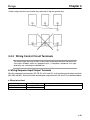
H Wiring on the Output Side of Main Circuit
D Connecting the Terminal Block to the Load
Connect output terminals U, V, and W to motor lead wires U, V, and W, respectively.
D Never Connect Power Supply to Output Terminals
! Caution
Never connect a power supply to output terminals L1, N/L2, and L3.
If voltage is applied to the output terminals, the internal mechanism of the Inverter
will be damaged.
D Never Short or Ground the Output Terminals
! Caution
If the output terminals are touched with bare hands or the output wires come into
contact with the Inverter casing, an electric shock or grounding will occur. This is extremely hazardous. Also, be careful not to short the output wires.
D Do Not Use a Phase Advance Capacitor or LC/RC Noise Filter
Never connect a phase advance capacitor or LC/RC Noise Filter to the output circuit. Doing so may
result in damage to the Inverter or cause other parts to burn.
3-16
Chapter 3
Design
D Do Not Use an Electromagnetic Switch
Do not connect an electromagnetic switch or magnetic contactor to the output circuit. If a load is connected to the Inverter during operation, an inrush current will actuate the overcurrent protective circuit in
the Inverter.
D Installing a Thermal Relay
This Inverter has an electronic thermal protection function to protect the motor from overheating. If,
however, more than one motor is operated with one Inverter or a multipolar motor is used, always install
a thermal relay (THR) between the Inverter and the motor and set to “0.0” (no thermal protection) for
constant No. 31 (“THR” indicator).
In this case, program the sequence so that the magnetic contactor on the input side of the main circuit is
turned off by the contact of the thermal relay.
D Installing a Noise Filter on the Output Side
Connect a Noise Filter to the output side of the Inverter to reduce radio noise and induction noise.
3G3EV
Power supply
3G3IV-PLF
Noise Filter
Signal line
Induction noise
Controller
Radio noise
AM radio
Induction Noise:
Electromagnetic induction generates noise on the signal line, causing the controller to malfunction.
Radio Noise:
Electromagnetic waves from the Inverter and cables cause the broadcasting radio
receiver to make noise.
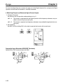
D How to Prevent Radio Noise
Radio noise is generated from the Inverter as well as the input and output lines. To reduce radio noise,
install Noise Filters on both input and output sides, and also install the Inverter in a totally enclosed steel
box.
3-17
Chapter 3
Design
The cable between the Inverter and the motor should be as short as possible.
Steel box
Metal pipe
3G3EV
Power supply
Noise
Filter
Noise
Filter
D Cable Length between Inverter and Motor
If the cable between the Inverter and the motor is long, the high-frequency leakage current will increase,
causing the Inverter output current to increase as well. This may affect peripheral devices. To prevent
this, adjust the carrier frequency (set in n37) as shown in the table below.
Cable length between Inverter and motor
Carrier frequency (n37)
Note
20 m max.
10 kHz max. (1, 2, 3, 4)
100 m max.
5 kHz max. (1, 2)
When the cable length between Inverter and motor exceeds 20 m, the system must be confirmed for conformity to the EMC Directives.
H Ground Wiring
• Always use a ground terminal with the following ground resistance.
200-VAC Class:
100 Ω or less
400-VAC Class:
10 Ω or less
Also connect to the power supply neutral.
• Do not share the ground wire with other devices such as a welder or power tool.
• Always use a ground wire that complies with technical standards on electrical equipment. Route the
ground wire so that the total length is as short as possible.
3-18
Chapter 3
Design
• When using more than one Inverter, be careful not to loop the ground wire.
3-2-3 Wiring Control Circuit Terminals
The control signal line must be 50 m or less and must be separated from the power line.
Use batch shielded cable for sequence input. If frequency references are input
externally, use a twisted-pair shielded line.
H Wiring Sequence Input/Output Terminals
Wire the sequence input terminals (SF, SR, S1 to S3, and SC), multi-function contact output terminals
(MA, MB, and MC), and multi-function photocoupler output terminals (PA and PC) as described below.
D Wires to be Used
Wire type
Single wire
Stranded wire
Wire size
0.5 to 1.25 mm2
0.5 to 0.75 mm2
Wire to be used
Polyethylene-shielded
y y
cable
3-19
Chapter 3
Design
D Solderless Terminals for Control Circuit Terminals
The use of solderless terminals for the control circuit terminals is recommended because solderless
terminals are easy to connect securely.
d1 dia.
d2 dia.
Wire thickness
0.5 mm2
Model
A1 0.5-8WH
d1
d2
1.00
2.60
0.7 mm2
1 mm2
A1 0.75-8GY
A1 1-8RD
1.20
1.40
2.80
3.00
Manufacturer
Phoenix Contact
Terminal
SF, SR, S1 to
S3, SC, FS, FR,
FC
MA,, MB,, MC
D Wiring Method
• Wire each terminal as follows:
a) Loosen the terminal screw with a thin-slotted screwdriver.
b) Insert the wire from underneath the terminal block.
c) Tighten the terminal screw firmly.
• Always separate the control signal line from the main circuit cables and other power cables.
• Insulate the shielded sections with insulation tape, etc., from other signal lines or equipment and
ground on the Inverter side.
Thin-slotted screwdriver
Control circuit
terminal block
Length of stripped
portion: Approx. 5.5 mm
Do not solder this portion.
(Otherwise, faulty contact may result.)
Wire
3-20
Chapter 3
Design
H Wiring Frequency Reference Input Terminals
If frequency references are input using a D/A Unit (digital-to-analog converter) or external power supply,
wire the frequency reference input terminals (FR and FC) as described below.
D Wires to be Used
Always use twisted-pair shielded wires to prevent malfunctions due to noise.
Wire type
Single wire
Stranded wire
Wire size
0.5 to 1.25 mm2
0.5 to 1.25 mm2
Wire to be used
Polyethylene-insulated
y y
cable for instrumentation ((with
shield)
hi ld)
D Wiring Method
• The wiring procedure is the same as for sequence input/output terminals, described previously.
• Always separate the cables from the main circuit cables and other power cables.
• Connect the shield to the ground terminal of the Inverter. Do not connect to the controller.
• Insulate the shield with tape to prevent it from coming into contact with other signal lines and devices.
H Tightening Torque of Control Circuit Terminals
Tighten the control circuit terminals to the torque of 0.5 N S m which is the same torque as for the M3
screws.
Note 1. Applying a torque of greater than 0.5 N S m may damage the terminal block.
Note 2. If the tightening torque is insufficient, wires may be disconnected.
H Selection of Frequency Reference or Sequential Input
! Caution
Do not touch the terminals of the Inverter within one minute after the Inverter is
turned off, otherwise an electric shock may be received.
Mounting or Dismounting the Digital Operator
1. To dismount the Digital Operator, insert a flat-blade screwdriver into the groove on the bottom of the
Digital Operator and lift the Digital Operator.
2. After the connector is removed, hold the lower part of the Digital Operator and slide the Digital Operator downwards.
3-21
Chapter 3
Design
To mount the Digital Operator, connect the upper part of the Digital Operator first, and press the Digital
Operator until the internal connector is securely connected.
D Selecting Frequency Reference Input (Current Input)
1. Change of Constant
Set constant n02 for operation mode selection to 4 or 5.
n02 = 4:
The Inverter is operated with the Digital Operator while frequency references are provided as terminal input (current input).
n02 = 5:
The Inverter is operated and frequency references are provided through terminals (current input).
2. SW1 Selector
Set SW1 to ON by sliding SW1 to the right to operate the Inverter with current input.
Sequential Input Selection (NPN/PNP Transistor)
Select NPN or PNP transistor input with SW2.
24 V
S1 to S3 3.3 K
S1 to S3 3.3 K
0.1 µ
3-22
24 V
0.1 µ
4
Chapter 4
Specifications
4-1
4-2
Specifications of Main Unit
Specifications of Noise Filter
Specifications
4-1
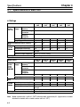
Chapter 4
Specifications of Main Unit
H Ratings
Model 3G3EV-
A2001(M)- A2002(M)- A2004(M)- A2007(M)- A2015(M)CUE
CUE
CUE
CUE
CUE
Three
Power
Rated voltage and Three-phase, 200 to 230 VAC, 50/60 Hz
phase,,
supply
p
pp y
frequency
200 VAC
Allowable voltage –15% to 10 %
fluctuation
Allowable
±5%
frequency
fluctuation
Heating value (W)
11.9
18.8
33.2
51.7
71.6
Weight (kg)
0.5
0.6
0.9
1.3
1.5
Maximum applicable motor capacity
0.1
0.2
0.4
0.75
1.5
(kW)
Output
p
Rated output capacity (kVA) 0.3
0.6
1.1
1.9
2.7
specifiifi
Rated output current (A)
0.8
1.5
3.0
5.0
7.0
cations
Rated output voltage
Three-phase, 200 to 230 VAC (Corresponds to the input
voltage)
Maximum output frequency
400 Hz (Parameter setting)
Cooling method
Self-cooling
Model 3G3EV-
AB001(M)- AB002(M)- AB004(M)- AB007(M)- AB015(M)
CUE
CUE
CUE
CUE
-CUE
Single
Power
Rated voltage and Single-phase/Three-phase, 200 to 240 VAC, 50/60 Hz
p
pp y
phase//
supply
frequency
Three
Allowable voltage –15% to 10 %
phase,
fluctuation
200 VAC
Allowable
±5%
frequency
fluctuation
Heating value (W)
12.6
20.3
25.3
55.3
78.4
Weight (kg)
0.5
0.6
1.3
1.3
2.0
Maximum applicable motor capacity
0.1
0.2
0.4
0.75
1.5
(kW)
Output
p
Rated output capacity (kVA) 0.3
0.6
1.1
1.9
2.7
specifiifi
Rated output current (A)
0.8
1.5
3.0
5.0
7.0
cations
Rated output voltage
Three-phase, 200 to 230 VAC (Corresponds to the input
voltage)
Maximum output frequency
400 Hz (Parameter setting)
Cooling method
Self-cooling
Note
4-2
Model numbers with a suffix of “-CUE” indicate models approved by UL. (Approval has not been
obtained for models with a model number suffix of “-CE.”)
Chapter 4
Specifications
Model 3G3EVThree
phase,,
p
400 VAC
Power Rated voltage and
supply
pp y frequency
Allowable voltage
fluctuation
Allowable frequency
fluctuation
Heating value (W)
Weight (kg)
Maximum applicable motor capacity
(kW)
Output
p
Rated output capacity (kVA)
specifiifi
Rated output current (A)
cations
Rated output voltage
Maximum output frequency
Cooling method
---
A4002(M)- A4004(M)- A4007(M)- A4015(M)CUE
CUE
CUE
CUE
Three-phase, 380 to 460 VAC, 50/60 Hz
–15% to 10 %
±5%
---
25.5
1.0
0.2 (0.37)
34.7
1.0
0.4 (0.55)
56.0
1.5
0.75 (1.1)
78.5
2.0
1.5 (1.5)
0.9
1.4
2.6
3.7
1.2
1.8
3.4
4.8
Three-phase, 380 to 460 VAC (Corresponds to the input
voltage)
400 Hz (Parameter setting)
Self-cooling
H General Specifications
Installation type
Installation site
Ambient temperature for operation
Humidity
Ambient temperature for storage
Altitude
Vibration resistance
Cable length between Inverter and
motor
Applicable standards
Enclosed wall-mounted type (IP20)
Indoor (free from corrosive gases and dust)
–10° to 50°C
90% or less (no-condensing)
–20° to 60°C
1,000 m max.
Less than 20 Hz:
1G {9.8 m/s2} or less
20 to 50 Hz:
0.2G {1.96 m/s2} or less
20 m max. (When the cable length exceeds 20 m, the system
must be confirmed for conformity to the EMC Directives. )
prEN50178, EN50081, EN50082 (with RFI filter and shielded
cable)
UL/CUL standards
4-3
Chapter 4
Specifications
H Control Characteristics
Control method
Frequency control range
Frequency accuracy
(temperature fluctuation)
Sine-wave PWM method (automatic torque boost)
0.5 to 400 Hz (standard model: 1.5 to 400 Hz)
Digital command:
±0.01% (–10°C to 50°C)
Analog command:
±1% (25 ±10°C)
Frequency setting
Digital command:
resolution
0.1 Hz (less than 100 Hz), 1 Hz (100 Hz or more)
Analog command:
0.06 Hz (60 Hz)
Frequency output resolution 0.1 Hz (operation resolution)
Overload resistance
1 minute or less when 150% of rated output current is received
Frequency setting signal
0 to 10 VDC (20 kΩ) or 4 to 20 mA (250 Ω)
Note This setting can be switched using the internal DIP switch.
Acceleration/Deceleration
0.0 to 999 seconds (acceleration and deceleration times are set separately)
time
Braking torque (continuous Approximately 20%
regenerative braking)
Note 125% to 220% when braking resistor is externally installed.
Voltage/Frequency
Simple V/f pattern setting
characteristics
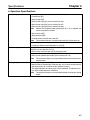
H Protection Functions
Motor protection
Instantaneous overcurrent
protection
Overload protection
Overvoltage protection
Voltage drop protection
Electronic thermal protection
When 250% of the rated output amperage is exceeded
When 150% of the rated output amperage is exceeded for one minute
Stops the system when DC voltage of the main circuit exceeds
approximately 410 V (400-VAC class: 820 V)
3G3EV-A2j: Stops the system when voltage drops below approximately
200 VDC
3G3EV-ABj:
Stops the system when voltage drops below approximately
160 VDC
3G3EV-A4j:
Protection from
instantaneous power
interruption
Radiation fin overheat
protection
Ground protection
4-4
Stops the system when voltage drops below approximately
400 VDC
Stops the system when a power interruption lasts for 15 ms or more.
Operation can be continued by setting constant No. 36 as follows:
• Operation is continued if a power interruption only lasts for approximately 0.5
second or less.
• Operation is continued unconditionally.
Detects a fin temperature of 110 ±10°C
Overcurrent level protection
Chapter 4
Specifications
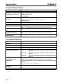
H Operation Specifications
Control input
Three photocoupler input terminals (24 VDC, 8 mA)
• Forward/stop [SF]
• Reverse/stop [SR]
• Multi-function input [S1] (set in constant No. 06)
• Multi-function input [S2] (set in constant No. 07)
• Multi-function input [S3] (set in constant No. 08)
Note When 3-wire sequence mode (constant No. 01 = “9”) is selected, the
terminals become as follows:
• Run command [SF]
• Stop command [SR]
• Forward/reverse rotation command [S1]
Note The standard Inverters are not provided with S2 and S3 terminals.
One analog input terminal (0 to 10 VDC or 4 to 20 mA)
Control output
• Frequency reference input [Between FC and FR]
One SPDT relay contact output terminal [MA, MB]
(30 VDC and 1A; 250 VAC and 1A)
• Multi-function contact output (set in constant No. 09)
One photocoupler input terminal [PA] (48 VDC, 50 mA)
Analog output
• Multi-function photocoupler output (set in constant No. 10)
Note The standard Inverters are not provided with the multi-function photocoupler output.
One analog voltage output [AM] (0 to 10 VDC, 2 mA)
• Multi-functional analog output (Constant No. 44 is used to set the function
and constant No. 45 is used to set the multiplying factor.)
The output frequency or output current can be monitored. The Inverter is factory-set to output frequency monitoring.
Note The standard Inverters are not provided with the multi-function analog
output.
4-5
Specifications
4-2
Chapter 4
Specifications of Noise Filter
Three-phase 200-VAC Noise Filter
Inverter
Single-phase Noise Filter (Soshin Electric)
Model 3G3EVInverter
Model 3G3EVRated voltage Rated current
Weight (kg)
capacity (kVA)
(V)
(A)
PNF3006A-YN
250 VAC
6
Approx.
pp
0.8
A2001(M)-CUE
0.3
A2002(M)-CUE
0.6
A2004(M)-CUE
1.1
PNF3010A-YN
10
A2007(M)-CUE
1.9
A2015(M)-CUE
2.7
Single-phase 200-VAC Noise Filter
Inverter
Single-phase Noise Filter (Soshin Electric)
Model 3G3EVInverter
Model 3G3EVRated voltage Rated current
Weight (kg)
capacity (kVA)
(V)
(A)
PNF2003A-YN
250 VAC
3
Approx.
pp
0.5
AB001(M)-CUE
0.3
AB002(M)-CUE
0.6
PNF2010A-YN
10
Approx.
pp
0.6
AB004(M)-CUE
1.1
AB007(M)-CUE
1.9
AB015(M)-CUE
2.7
PNF2020A-YN
20
Approx. 1.0
Three-phase 400-VAC Noise Filter
Inverter
Single-phase Noise Filter (Soshin Electric)
Model 3G3EVInverter
Model 3G3EVRated voltage Rated current
Weight (kg)
capacity (kVA)
(V)
(A)
PNF3007C-YN
460 VAC
7
Approx.
pp
1.0
A4002(M)-CUE
0.9
A4004(M)-CUE
1.4
A4007(M)-CUE
2.6
A4015(M)-CUE
3.7
4-6
Chapter 4
Specifications
H Dimensions
D 3G3EV-PNF3006A-YN/-PNF3010A-YN
5
56 ± 1
74 ± 3
5.0 dia.
84±1
118±1
75 max.
128±2
4-7
Chapter 4
Specifications
D 3G3EV-PNF2003A-YN/-PNF2010A-YN
max.
1
Two, 5.0 dia.
4-8
Chapter 4
Specifications
D 3G3EV-PNF2020A-YN
74 +
–2
56 +
–1
5.0 dia.
5
93±1
118±1
74 max.
128±2
4-9
Chapter 4
Specifications
D 3G3EV-PNF3007C-YN
75 max.
95±2
118±1
128±2
4-10
108 +
–2
96 +
–1
Four, 5.0 dia.
Index
A–C
AC reactor, main circuit, input side, 3-15
cables, length, main circuit, 3-18
cautions, wiring, 3-6
clamp core, main circuit, 3-13
connection diagrams, 3-10
constant settings, warning, 1-3
control circuit
analog output terminals, 3-10
input terminals, 3-9
output terminals, 3-9, 3-10
terminal connections, 3-11
wiring, 3-19
M
magnetic contactor, main circuit
input side, 3-15
output side, 3-17
main circuit
input terminals, 3-8
output terminals, 3-8
terminal connections, 3-10
wiring, 3-11
MCCB, main circuit, 3-14
models, list, 1-2, 2-2
molded-case circuit breaker. See MCCB
N–R
D
nameplate, 1-2
dielectric strength test, warning, 1-3
Noise Filters, main circuit, 3-12
output side, 3-16, 3-17
Digital Operator
mounting, 3-21
warning, 1-3
nomenclature
Digital Operator, 2-5
Inverter, 2-4
dimensions
Inverter, 3-2
Noise Filter, 4-7
phase advance capacitor, main circuit, output side, 3-16
precautions, 1-3
radio noise, main circuit, output side, 3-17
E–H
electromagnetic switch, main circuit, output side, 3-17
EMC Directives, conformance, 2-3
Noise Filters, 3-12
frequency reference
input, selection, 3-22
wiring, control circuit, 3-21
residual voltage, warning, 1-3
S
sequential input
control circuit, wiring, 3-19
selection, 3-22
signals, warning, 1-3
ground, wiring, main circuit, 3-18
solderless terminals, round, control circuit, 3-20
ground fault interrupter, main circuit, input side, 3-15
specifications
Inverter, 4-2
Noise Filter, 4-6
heat sink, 1-3
surge absorber, main circuit, input side, 3-15
I–L
installation, 3-4
conditions, 3-4
orientation, 3-4
space, 3-4
Low-voltage Directives. See LVD Directives
LVD Directives, conformance, 2-3
MCCB, 3-14
T
temperature, 3-5
terminals, 3-7
control circuit, 3-9
main circuit, 3-8
thermal relay, main circuit, output side, 3-17
I-1
Index
W
warnings, 1-3
constant settings, modifying, 1-3
dielectric strength test, 1-3
Digital Operator, 1-3
heat sink, 1-3
residual voltage, 1-3
signals, modifying, 1-3
wiring, 3-6
modifying, 1-3
I-2
wires
frequency reference input, 3-21
sequential input, 3-19
sizes, control circuit, 3-21
solderless terminals, 3-20
wiring
caution, 3-6
warning, 1-3, 3-6
Revision History
A manual revision code appears as a suffix to the catalog number on the front cover of the manual.
Cat. No. I521-E1-04
Revision code
The following table outlines the changes made to the manual during each revision. Page numbers refer to the
previous version.
Revision code
1
Date
April 1997
2
November 1997
Revised content
Original production
Information on new models added throughout the manual.
Page 1-2: Model number description changed.
Page 2-2: Table of available models changed. Note in Required Conditions
corrected.
Page 3-3: Three-phase 400-VAC input models added.
Page 3-5: Warning to connect the ground to the supply neutral added for the
400-VAC models.
Page 3-7: Descriptions of terminals changed.
Page 3-8: Information added above the table for the input terminals.
Pages 3-9, 3-11: Changes to the diagram made to include the 400-VAC models. Note added also.
Page 3-10: Information added to the frequency reference input of the control
circuit diagram. Wire size table changed. Note added also.
Page 3-11: Information added to the beginning of Wiring Power Supply. Noise
filter table changed.
Page 3-12: LVD conformance table changed.
Page 3-13: Braking Resistor Unit information removed from Installing a Magnetic Contactor. Information added to Installing an AC Reactor. A section on
wiring a Braking Resistor/Braking Resistor Unit has been added.
Page 3-15: Ground resistance information added to Ground Wiring.
Page 3-18: A section on the tightening torque of control circuit terminals
added.
Page 4-2: Ratings changed.
Page 4-3: Information on 400-VAC models added to the overvoltage and voltage drop descriptions in Protection Functions.
Page 4-5: Noise Filter tables changed. New Noise Filter dimensions added.
3
November 1998
Models with the special specification “-CE” have been removed throughout the
manual. Information on new three-phase, 200-VAC models added throughout the
manual.
Page 2-3, 3-7, 3-11, 4-6: Note on the unavailability of noise filter that conforms
to EC Directives removed.
Page 4-3: Applicable standards added to General Specifications.
Page 4-7: 3G3EV-PNF3006A-YN/-PNF3010A-YN dimensions added.
04
September 2005
Following changes made to front matter.
General precautionary notes added to the first page.
Notice: Information on general precautions notation added.
Read and Understand this Manual: Information on liability and warranty added.
R-1