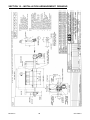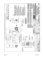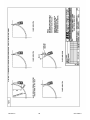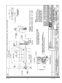
1
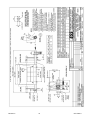
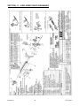
Durt Tracker Doctor Blade Primary Cleaner Installation Operations Manual Revision A B C D E F G H I J K L Revision L Description of Change Added Final Checklist General Review and Update; Added Warranty Registration Updated Melbourne Address & Removed SA Address Drawings updated Final Checklist Updated Items 4 & 5 Reversed Tensioner information Updated Updated Drawings Removed Mts Isa contact details Updated format of manual Updated office details Updated ESS & Martin Logo & Karratha contact details Updated drawing F0035 & inserted F0495 1 Changed By AS TT/AS SH CW SH KOR KOR KO KO KO KO KO Date 28/5/07 02/11/07 3/08/09 02/10/09 15/04/10 25/5/11 17/04/12 12/6/12 5/2/13 10/3/14 4/6/14 3/11/14 03/11/2014 ENGINEERING SERVICES and SUPPLIES OFFICE DETAILS Location CURRUMBIN Address 11 – 13 Traders Way PO Box 121 Currumbin QLD 4223 [email protected] Unit 11 / 115 Roberts Street PO Box 1861 Emerald QLD 4720 [email protected] Unit 2/34 Chapple Street PO Box 1475 Gladstone QLD 4680 [email protected] Unit A 255 Dugan St Kalgoorlie WA 6430 PO Box 10471 Kalgoorlie WA 6433 [email protected] 336 Wickerson Way , Bulgarra, Karratha, WA 6714. [email protected] EMERALD GLADSTONE KALGOORLIE KARRATHA MACKAY MAITLAND PERTH TOWNSVILLE SOUTH AUSTRALIA VICTORIA WOLLONGONG 1 Progress Street Paget, QLD 4740 PO Box 5755 Mackay Mail Centre QLD 4741 [email protected] Unit 2 Barton Court 6 Johnson Street Maitland NSW 2320 [email protected] 19 Clavering Road Bayswater WA 6053 26 Midas Road Malaga WA 6090 [email protected] Unit 6 40-42 Carmel St Garbutt QLD 4814 [email protected] 5 Cormorant Court. Middleton. SA . 5213 [email protected] Unit 4 / 314 Governor Road Braeside VIC 3195 [email protected] Unit 1 / 20 Doyle Avenue PO Box 343 Unanderra NSW 2526 [email protected] Phone & Fax Phone: (07) 5589 2000 Fax: (07) 5521 0347 Phone: (07) 4982 4855 Fax: (07) 4987 5118 Phone: (07) 4972 3759 Fax: (07) 4972 2866 Phone: (08) 9021 7991 Fax: (08) 9021 7291 Phone: (08) 9144 0689 Fax: (08) 9144 0682 Phone: (07) 4952 4600 Fax: (07) 4952 4717 Phone: (02) 4932 3544 Fax: (02) 4932 3611 Phone: (08) 9370 3155 Fax: (08) 9272 5130 Phone: (07) 4755 2776 Fax: (07) 4779 6236 Mobile: 0408 948 175 Phone: (03) 9580 0388 Fax: (03) 9587 5199 Phone: (02) 4272 4422 Fax: (02) 4272 4434 TOLL FREE 1800 074 446 FROM ANYWHERE IN AUSTRALIA VSS TOLL FREE 1800 300 877 Revision L 2 03/11/2014 WARRANTY NOTE ESS WARRANTS the Durt Tracker Doctor Blade Primary Cleaner to be free of defects both in materials and workmanship for a period of 12 months from the date of despatch of the product from the ESS factory. The warranty given by ESS in this regard will extend only to replacing or repairing product shown to be defective. The warranty also is subject to the following restrictions: (a) Installation of the product contrary to the instructions contained in the supplied manual will void such warranty absolutely; (b) The warranty will not extend to any liability for injuries incurred and which result from the use of the product contrary to the instructions in the manual; (c) Save as prescribed by law, ESS will not be liable for any damage sustained by a purchaser or a third party by way of consequential loss arising out of defects in the product. You are asked to note that ESS offers purchasers a service whereby either: (a) It will install the product and certify the correctness of such installation, or (b) Certify the correctness or otherwise of the installation of the product by third parties. This certification service is designed to ensure that you obtain the full benefit of the ESS warranty hereby provided. If you would like to take advantage of the installation certification service provided, please contact ESS regarding the service. Refer to the Final Checklist at the back of this manual. Visit the ESS website www.esseng.com.au to register your product warranty. THE CONTENTS OF THIS MANUAL ARE COPYRIGHT TO: ESS ENGINEERING SERVICES AND SUPPLIES PTY LTD ALL RIGHTS RESERVED Information contained herein is for use in the operation of the Durt Tracker Doctor Blade Primary Cleaner, purchased from ESS and cannot be passed on to any other party without express permission, in writing, from ESS. Revision L 3 03/11/2014 INDEX SECTION 1 SAFETY SECTION 2 INTRODUCTION SECTION 3 PREPARATION FOR INSTALLATION SECTION 4 INSTALLATION SECTION 5 OPERATION OF TENSIONERS SECTION 6 COMMISSIONING SECTION 7 OPERATOR TRAINING SECTION 8 ROUTINE MAINTENANCE AND SERVICE SECTION 9 TROUBLE SHOOTING SECTION 10 INSTALLATION ARRANGEMENT DRAWING SECTION 11 EXPLODED PARTS DRAWING SECTION 12 FINAL CHECKLIST Revision L 4 03/11/2014 SECTION 1 - SAFETY The DURT TRACKER is designed to be quickly and easily serviced by appropriate personnel. Under no circumstances should servicing or installation of the cleaner be carried out whilst the belt is in operation. The conveyor must be shut down and locked out before any person enters or reaches into the conveyor enclosure. Ensure that only suitably qualified and trained personel install and service this product. Ensure that all site and statutory safety procedures are followed. Revision L 5 03/11/2014 SECTION 2 - INTRODUCTION The Durt Tracker Doctor Blade is a conveyor belt Primary Cleaner. It is normally mounted on the face of the conveyor head pulley and is designed to peel off the thick layer of loosely adhering material that often accounts for 85%-95% of carryback. The Durt Tracker Doctor Blade is normally used in conjunction with at least one secondary cleaner, such as the Inline Premium Secondary Cleaner, and often with a water spray system. The blade material is one piece cast urethane. These segmented blades can be easily removed by sliding on and off the mainframe track. Important points to remember concerning the Durt Tracker Doctor Blade are: 1. The cleaner is directional - it will only clean a belt travelling in the design direction however, the cleaner will not be damaged or affected by belt direction reversal. 2. The cleaner is suitable for use on crowned head pulleys and damaged or grooved belts. The urethane blades quickly conform to the belt profile. 3. For slow moving belts, the cleaner should be positioned lower on the head pulley to ensure the blades are clear of the main material flow. 4. For belts greater than 1500mm wide a tensioner is required on both sides to ensure equal pressure across the cleaning face. 5. For belts greater than 1800mm wide, or for certain heavy duty applications, a mainframe stiffener is required. Revision L 6 03/11/2014 SECTION 3 - PREPARATION FOR INSTALLATION 1. CHECK INSTALLATION DRAWINGS - Ensure that you have the correct drawings and equipment for your conveyor(s). 2. PRE-ASSEMBLE THE CLEANER(S) AND MOUNTS - Do this in your workshop or similar free area, rather than at the Conveyor. This will enable you to: verify all required equipment is present familiarise yourself with the cleaner assembly allow you to plan the installation, reducing installation time. 3. ASSEMBLE THE NECESSARY TOOLS & SAFETY EQUIPMENT REQUIRED FOR THE INSTALLATION 4. OBSERVE THE CONVEYOR WHILE RUNNING AND CONVEYING MATERIAL Observe the material trajectory Observe the belt direction - does it reverse or roll back? Observe the belt splice condition Does the belt run true, or track off to one side? Is the Head Pulley out-of-round? Consult ESS if any UNUSUAL conditions are observed in the above. These conditions may result in recommendation of a different installation position or even a different cleaner. Revision L 7 03/11/2014 SECTION 4 - INSTALLATION DANGER! Conveyor must be shut down and locked out before any installation or service work is performed. WARNING! If installation is to be done in an enclosed area, test atmosphere for gas level or dust content. Follow all welding and safety guidelines. NOTE 1 For original equipment installation, where cleaner cutouts and brackets have been fabricated into the chute during construction, ignore steps 1 and 2 . NOTE 2 For installation on enclosed head pulley chutework, draw all dimension lines on chute wall. In applications where head pulley is not enclosed, custom designed brackets are necessary to ensure correct cleaner position. Step 1. Locating Mainframe’s Centreline Using the typical installation drawing supplied in this manual, locate the mainframe’s centreline on both sides of the conveyor. Measure radially 100mm from the face of the belt. From this point draw an arc using the pulley’s centreline as the centre point. The centreline of the mainframe can be located anywhere along the radius as long as the blades do not lie in the material’s trajectory. The optimum position is for the blade tips to be between 0 and 15 below the horizontal centreline. NOTE: Revision L Material trajectory is defined as the path of the material being discharged from the belt. 8 03/11/2014 Verify Mainframe Position before Proceeding Position the selected tensioner/mount assembly over the centreline marks for the mainframe. Verify that the mounts fit, and that adequate room is available to tension the cleaner. If used, position the CYA door frame to ensure it fits. If mounts or door frame interfere with structural members, it may be necessary to locate the cleaner elsewhere on the 100mm offset radius. If the tensioner only interferes, remember that the tensioner can be rotated to several different mounting positions by removal of the four countersunk screws. Once mounting position is confirmed, proceed. Step 2. At the selected mainframe mounting positions, mark out and cut the mainframe and mount fastener holes (if required) in each side of the chute. Refer to the installation drawing at the back of this manual. If a CYA door is to be installed, use the door frame as a template to mark the door cut-out on the operator side. Proceed to cut the door hole, but ensure that the marked centre lines of the cleaner are not totally removed - you will need these to position the mainframe. If a stand-off bracket is to be bolted over a CYA door, the mounting holes also have to be cut. Step 3. The Durt Tracker Mainframe is a combination of extruded polyethylene, steel tubing, and telescoping mounting pipes. The telescoping mounting pipes allow precise length adjustment each side, removing the need for site trimming. Remove the blades if they have been mounted on the mainframe. Do this by loosening the blade lock screw from the end to be the operator side. Remove blade lock and blades by sliding them out of the track end using the pull-strap. Insert the mainframe without the blades through the inspection window. Pass one end of the mainframe telescoping pipe through the mount hole on the far side, then the other through the operator side mount. Step 4 Loosen the lock screws on the bottom of the track, and either extend or retract the telescoping pipe ends as required. Slide the operator and far side mounts on to the telescoping pipes, then tack weld, clamp, or loosely bolt the mounts to the chute walls. If a stand-off bracket is to be used over a CYA door, and the cutout has been made, fit the operator side mount to the appropriate stand-off bracket, and tack weld, clamp or bolt the stand-off bracket in the desired position. Position the orange extrusion so that it is centred on the belt. Once centred, lightly tighten lock screws on the bottom of the track. This will hold the telescoping pipes in place. This procedure will need to be repeated at the final step. (Note: Slide the CYA door frame loosely on to the pipe end before the mount, to save later mount removal). Revision L 9 03/11/2014 Step 5. Check the position of the mainframe. Is the centre line of the mainframe positioned 100mm from the belt face? Is the mainframe level, or equal to the pulley shaft? Is there at least 152mm clear at one end of the track to remove and replace blades? Ensure the far side blade lock is fitted. The lock must be sufficiently secure to hold the blades in place. Lay the pull-strap in the track with the smaller looped end toward the far side blade lock. Slide blades on top of pull-strap and into track. Place operator side blade lock in track, and secure to finish blade installation. By hand, rotate the pipe until the blade tips lightly contact the belt. Do the blade tips all touch the belt at the same time? (Note: Slight inconsistencies in belt thickness, and blade shape, accounting for small gaps between blade and belt, will quickly be taken up by blade flexure on tensioning). For crowned head pulleys, ensure that the outside blades on each side are an equal distance from the belt, whilst the centre blade is touching. Again, these gaps will quickly close on tensioning. If any questions above have been answered “NO”, take appropriate action to correct the installation. If all questions are answered “YES”, proceed. Step 6. Fully weld or bolt the cleaner mounts, brackets and CYA door frame to the chute wall. If not already done, fit the tensioner assembly(ies)to the mount(s). Centre the blades on the belt. All ESS cleaners are designed to clean an area narrower than the actual belt width. This is to allow for a small amount of lateral movement of the belt and to protect the edge of the belt from possible damage. Loosen the lock screws on the bottom of the track and adjust the telescoping pipe ends to the required length. Firmly tighten the lock screws. Lateral movement of the mainframe is prevented by the tensioner’s locking hubs, or a lock collar on the far side mount when only a single tensioner is used(i.e. on belt widths less than 1600mm). Lock these items in position, allowing about 1-2mm of end float in the cleaner mainframe. Revision L 10 03/11/2014 Step 7. WHERE A CYA DOOR IS FITTED. Measure the position of the mainframe in relation to the CYA door frame. Mark this position on the CYA door rubber cover, and cut a neat hole, approximately 50mm diameter in the cover. Cut a straight line from this hole to the nearest edge of the rubber cover. Install the rubber cover over the mainframe pipe, and push into place on the door frame. Anchor the loose end of the cover lanyard. Revision L 11 03/11/2014 SECTION 5 - OPERATION OF THE TENSIONERS ESS Durt Tracker Doctor Blade Cleaners are mounted to the conveyor structure via Shock Mounts or Flex Mounts. The Shock Mount has a set of four threaded holes as shown in Figure 1 and Figure 2. The Flex Mount is a steel mount plate with a urethane insert as shown in Figure 3. Mild Steel Shock Mount FIG. 1 Stainless Steel Shock Mount FIG. 2 Flex Mount FIG. 3 Revision L 12 03/11/2014 5.1 – SPRING TENSIONER - INTRODUCTION The 40 NB Spring Tensioner is a simple, robust and reliable blade tensioning unit. The Spring Tensioner can be assembled to tension in either the clockwise or anticlockwise direction and has multiple mounting positions for each direction. Clockwise Tensioning Anti – Clockwise Tensioning Figure 1 The Spring Tensioner is available in two variations: Part number 09010309 is a Spring Tensioner Assembly suitable for attachment to a Primary Cleaner Shock Mount. This is often used as a retrofit to replace either a superseded ESS Pin Tensioner, or an ESS Air Tensioner. Part number 09010310 is a Spring Tensioner Assembly suitable for attachment to a Primary Flex Mount (see Figure 1). This is the most common mount and tensioner combination for a new cleaner, and is also used to replace the superseded ESS Counterweight Tensioner. Adding an “S” as a suffix to the above part numbers denotes a stainless steel model. Both types are available as a set with the mounts included. Where a complete cleaner is ordered, it would normally be supplied with the Flex Mounts as the lower cost option. Revision L 13 03/11/2014 5.1.1 Installation on Shock or TA Mount Shock Mount Operating Arm Spring and Adjusting Nut Anchor Plate Adjusting Rod Figure 2 Step 1 Fit the anchor plate to the mount using the four countersunk head screws. Ensure that the plate is in the correct orientation for the desired tensioning direction. The anchor plate can be flipped over for the opposite direction, but the anchor pin must be removed and installed on the other side. The anchor plate and the tensioner assembly can also be rotated to four different angles through 360° to suit site restrictions. Step 2 Slide the operating arm onto the cleaner mainframe, again ensuring that it is in the correct orientation for the desired tensioning direction. Step 3 Insert the threaded end of the adjusting rod through the operating arm slot, with the clevis end toward the anchor plate. Step 4 Fit the adjusting rod clevis onto the pivot plate pin and secure with clip provided. Step 5 Fit spring, nut and locknut to the threaded end of the adjusting rod. Only run the adjusting nut a few turns onto the adjusting rod. Do not try to adjust or compress the spring yet. Revision L 14 03/11/2014 Step 6 Using a pipe wrench or similar, rotate the cleaner until the blade tips are lightly touching the belt. With the operating arm fully retracted against the spring, lock the operating arm onto the cleaner mainframe by tightening the two lock screws. Ensure that the operating arm hub is 1-2mm clear of the mount to allow free rotation without excessive lateral movement of the mainframe. Step 7 Whilst still supporting the cleaner with the pipe wrench, adjust the nut (not locknut) against the spring until the spring just begins to compress. Release the pipe wrench. Step 8 For belts 1500mm and wider, tensioners are fitted to both sides. Repeat above procedure for other side. For cleaners with one tensioner only, fit the locking collar onto the far end of the cleaner mainframe, again locking it into position 1-2mm clear of the mount. Revision L 15 03/11/2014 5.1.2 Installation on Flex Mount Primary Flex Mount with M16 Bolts Washer, Nut & Locknut Cleaner Mount Spring Operating Arm Figure 3 Step 1 Fit the anchor plate to the mount using two of the existing mount bolts. There are M16 bolt holes provided for the Primary Flex Mount and M12 bolt holes for the Secondary Flex Mount. Ensure that the plate is in the correct orientation for the desired tensioning direction. The anchor plate can be installed on the opposite side mount holes for tensioning in the opposite direction. The anchor plate and tensioner assembly can also be turned upwards to suit site restrictions. Step 2 Slide the operating arm onto the cleaner mainframe, again ensuring that it is in the correct orientation for the desired tensioning direction. Step 3 Insert the threaded end of the adjusting rod through the operating arm slot, with the clevis end toward the anchor plate. Step 4 Fit the adjusting rod clevis onto the pivot plate pin and secure with clip provided. Step 5 Fit spring, nut and locknut to the threaded end of the adjusting rod. Only run the adjusting nut a few turns onto the adjusting rod. Do not try to adjust or compress the spring yet. Revision L 16 03/11/2014 Step 6 Using a pipe wrench or similar, rotate the cleaner until the blade tips are lightly touching the belt. With the operating arm fully retracted against the spring, lock the operating arm onto the cleaner mainframe by tightening the two lock screws. Ensure that the operating arm hub is 1-2mm clear of the mount to allow free rotation without excessive lateral movement of the mainframe. Step 7 Whilst still supporting the cleaner with the pipe wrench, adjust the nut (not locknut) against the spring until the spring just begins to compress. Release the pipe wrench. Step 8 For belts 1500mm and wider, tensioners are fitted to both sides. Repeat above procedure for other side. For cleaners with one tensioner only, fit the locking collar onto the far end of the cleaner mainframe, again locking it into position 1-2mm clear of the mount. Revision L 17 03/11/2014 5.1.3 – Spring Tensioner Adjustment Procedure. Note: The Spring Tensioner is mounted externally to the conveyor chute, and as such is normally able to be adjusted with the conveyor in service. Under no circumstances should any person reach into or enter a conveyor enclosure while the belt is running. For any conveyor belt cleaner service, maintenance or adjustment that requires entry to the conveyor enclosure by any part of the body, first ensure that the conveyor is shut down and locked out to site safety procedures. Warning: Contact with moving conveyor components can result in severe injury or death. To adjust the Spring Tensioner: Loosen the locknut away from the adjusting nut on the adjusting rod. Turn the adjusting nut until the cleaner blades are pressed against the belt, and the spring begins to compress. Continue until the spring is compressed to the height shown in the following table 1. Ensure that the correct height is used for the appropriate belt cleaner and belt width. If in doubt, contact ESS. Once the correct spring compression is achieved, run the locknut up against the adjusting nut, and use two wrenches to tighten the nuts together. For cleaners with dual tensioners, repeat this procedure on the opposite side. Table 1 Belt Width 450 600 750 900 1050 1200 1350 1500 1600 1800 2000 2200 2400 Primary Cleaners Spring Length No. of Turns 95 2.5 92 3.75 92 3.75 89 5 89 5 86 6.25 83 7.5 92 ** 3.75 89 5 89 5 86 6.25 86 6.25 86 6.25 ** Note: Cleaners for belts 1500 and wider have dual tensioners. The settings shown are for each tensioner. Revision L 18 03/11/2014 5.2 AIR TENSIONER - INTRODUCTION The Air Tensioner is a robust tensioner capable of delivering very precise blade to belt contact force, whilst allowing the cleaner to respond and absorb belt or pulley irregularities. The Air Tensioner can be assembled to tension in either direction and can be rotated to several positions through 360 to overcome site restrictions. Ensure that the tensioner is assembled to operate in the desired direction before mounting onto the mainframe. Clockwise Tensioning Anti-clockwise Tensioning ASSEMBLY STEPS The Air Tensioner assembly is normally despatched from the factory fully assembled and may only require the installer to slide the assembly onto the mainframe (as step 4) and secure the Air Tensioner bracket to the Shock Mount using the 4 countersunk head screws (as step 1). Disassembly will only be required if the tensioner is set-up to tension in the wrong direction. Revision L 19 03/11/2014 Step 1 Step 2 Step 3 Step 4 Step 5 Step 6 Step 7 Step 8 Fit the air tensioner bracket to the Shock Mount using the 4 countersunk head screws. Attach the airbag bracket to the air tensioner bracket. Bolt the blank end of the airbag to the operating arm. Slide the operating arm onto the mainframe with the airbag towards the airbag bracket side of the mount. Attach the open end of the airbag (this end has 3 tapped holes) to the airbag bracket. No air supply fittings should be connected at this point. Using a pipe wrench or similar, rotate the cleaner mainframe until the blade tips lightly touch the belt surface at the cleaning position. With the airbag fully compressed, secure the operating arm to the cleaner using the locking screws. Allow 12mm clearance between the operating arm and the Shock Mount to enable free rotation whilst minimising lateral movement. For cleaners on belts 1600mm or wider, repeat the above for the far side. For belts 1500mm and less, simply fit the lock collar onto the far side of the cleaner, again allowing 1-2mm lateral clearance. The cleaner is now ready for attachment of the air supply system. Connect all air fittings using a good quality liquid compound or “Gas Seal” thread tape. System 1 - NO PLANT AIR AVAILABLE System 2 - PLANT AIR AVAILABLE Revision L 20 03/11/2014 Step 9 Once all fittings are connected and secured, the Air Tensioner may be pressurised. Pressures are indicated in the following table. NOTE: Use these inflation pressures as a rough guide only. Belt speed, material, number of cleaners on belt and acceptable blade wear should be taken into account when setting pressures. DO NOT EXCEED 275 kPa (40 psi). IF YOU HAVE NEED OF ASSISTANCE, CONTACT YOUR LOCAL ESS OFFICE. BELT WIDTH 450 600 750 900 1050 1200 1350 1500 1600 1800 2000 2200 2400 PRESSURES KPa 34 48 55 69 83 83 90 90 55 62 69 83 97 PSI 5 7 8 10 12 12 13 13 8 9 10 12 14 * - Dual tensioners fitted - pressure per tensioner given. (Generally connected by balance tube.) Revision L 21 03/11/2014 SECTION 6 - COMMISSIONING Step 1. BACK THE CLEANERS AWAY FROM THE BELT Double check the items in previous sections - safety - preparation installation. Step 2. IS THE BELT EMPTY? Make sure there are no foreign objects such as tools or clean-up debris left on the belt. They may damage the belt cleaners or clog up the conveyor systems. Step 3. PLACE CONVEYED PRODUCT ON THE BELT Place some material on the belt before starting up system. This helps to quickly “Wear in” the blades and reduce the initial friction between the belt and the blades. Handfuls of conveyed material spaced along the belt will do. The belt may also be moistened with water. Step 4. START THE CONVEYOR Follow the established safety rules. Step 5. ADJUST DURT TRACKER DOCTOR BLADE CLEANER EVENLY ONTO THE BELT Refer to Section 5 - Operation of the Tensioners. Adjust the cleaner so that all of the blades are touching the belt with even pressure - DO NOT OVER-ADJUST. Each blade should be in contact and flexing back and forth with the irregularities of the belt surface. The Doctor Blade is designed to lightly ride on the surface of the belt and remove a large percentage of the carryback. Excessive pressure unnecessarily reduces the life of the blades without any increase in cleaner efficiency. Step 6. OBSERVE THE CLEANING ACTION Using a light, observe the belt and the action of the cleaner. Place material on the belt. Look for blades that are not touching the belt. Run for 5 minutes to get a good idea of the action and the effect of the splices on the belt cleaner. Step 7. DEMONSTRATE THE SYSTEM TO THE OPERATING SUPERVISORS AND CREW Call the supervisors responsible for maintenance and operation to the site. Make a short run of the system, putting material on the belt. Show the operator how to adjust and operate the system. Step 8. SECURE THE SYSTEM FOR PRODUCTION Follow plant procedure to secure the conveyor for actual production. Revision L 22 03/11/2014 SECTION 7 - OPERATOR TRAINING The decision to purchase ESS cleaning equipment has put within easy reach the reality of a clean plant. The last step is the correct training of personnel to maintain and service the equipment or employ ESS on a contract basis to maintain the cleaners so that they remain at optimum efficiency. The benefits of efficient cleaners outweigh the cost of maintaining the cleaners many times. If you wish to have your cleaning system maintained on a regular contract basis, contact ESS. If not, train your own personnel as follows: 1. Adhere to all local safety rules. 2. Give a “Hands On” instruction with the conveyor system shut down. 3. Give a “Hands On” instruction with the conveyor system running. 4. All service must be recorded and given to a person of responsibility. 5. Encourage the person being trained to look for possible problems developing on the system, eg. belt tracking excessively, tears or damage to belt, seized idlers, missing bolts, etc. A warning to the maintenance department to rectify small problems can save the company a lot of money in repairs and production costs. 6. Impress how important it is to maintain and service the cleaners correctly. Revision L 23 03/11/2014 SECTION 8 - ROUTINE MAINTENANCE AND SERVICE Regular inspection and servicing is the key to effective conveyor belt cleaning. It is recommended that the cleaner be inspected once per week. Actual service intervals will vary considerably from plant to plant. CAUTION! DO NOT REACH INSIDE THE CONVEYOR CHUTE UNDER ANY CIRCUMSTANCES WHILST THE CONVEYOR IS RUNNING. ROUTINE INSPECTION/TENSION: Step 1. Inspect the condition of the cleaner. Open the inspection door (if fitted) and observe the condition and action of the blades and cleaner. Step 2. If necessary (and if plant rules allow it), hose any material build-up from the blades or mainframe - DO NOT REACH INTO THE CHUTE WHILST CONVEYOR IS RUNNING. Step 3. If necessary, re-tension the cleaner - refer to Section 5. IF BLADE SERVICING IS REQUIRED. Step 1. Shut down and lock out the conveyor. Step 2. Release the tension and back the blades away from the belt. Sharply rap the blades against the belt to dislodge any build-up. Visually inspect the blades. If blades are clean, and not excessively worn, re-tension the cleaner. If material build-up is still present or blades are excessively worn, proceed. Step 3. Remove the operator side blade lock and slide the blade assemblies from the track. (Note: blades may require a slight rap with a hammer to loosen before sliding.) Step 4. Clean and inspect the blades - if blades are worn past the wear line on the back of the blade, replace with new (or refurbished) blades. Step 5. Re-install blades into mainframe track, followed by blade lock. Re-tension the cleaner as previously described. Step 6. Remove locks or tags and restart belt. Observe cleaner action and blade effectiveness. Replace CYA door cover - if fitted. Clean up work area. Revision L 24 03/11/2014 SECTION 9 – TROUBLE SHOOTING PROBLEM - Blades fold through on start-up. CAUSE Incorrect angle of installation dimensions Excessive tension attack Belt running dry Poor belt condition SOLUTION /. Relocate mounts so that the shaft is 100mm radial from the belt face on the head pulley Relax blade tension to maximum tension recommended in installation instructions Always place material on the belt for start-up or a little water if material is unavailable Repair belt, dress spices to smooth contour PROBLEM - Mainframe bent. CAUSE Mainframe undersized SOLUTION Stiffened mainframe required. Contact ESS for assistance Excessive tension Relax blade tension to maximum tension recommended in installation instructions Blades folded through See above Material build-up between blades/ Increase frequency of inspection and service once a mainframe and belt week Normal deflection A small amount of deflection is considered normal. Contact ESS if excessive deflection occurs PROBLEM - Higher blade wear rate than estimated. CAUSE Cleaner over-tensioned Incorrect blade material SOLUTION Tension cleaner enough to clean the belt only Contact ESS for re-appraisal PROBLEM - Insufficient cleaning - too much carryback. CAUSE Cleaner under-tensioned Build-up on blade Cleaner overloaded Secondary cleaner not functioning correctly Revision L SOLUTION Re-tension cleaner Rap blades against belt. Increase service frequency Add additional secondary cleaner Service the secondary cleaner 25 03/11/2014 SECTION 10 – INSTALLATION ARRANGEMENT DRAWING Revision L 26 03/11/2014 Revision L 27 03/11/2014 Revision L 28 03/11/2014 Revision L 29 03/11/2014 Revision L 30 03/11/2014 Revision L 31 03/11/2014 Revision L 32 03/11/2014 SECTION 11 – EXPLODED PARTS DRAWINGS Revision L 33 03/11/2014 SECTION 12 FINAL CHECKLIST Site: ____________________________ Number: _____________________ Site Equipment No./Location: _________________________ Date: ___________________ Site Contact: _________________________ Completed By: _____________________________________ (Circle Yes or No Below) 1. Was equipment to ESS Specification? _______________________________ Yes/No Drawing No. Ref: _________________________________________ Attached? Yes/No If No, WHY _______________________________________________________________________________ ________________________________________________________________________________________ Will this affect performance? Yes/No If Yes, WHY ______________________________________________________________________________ ________________________________________________________________________________________ 2. Was this a standard service inspection installation? Yes/No If No, WHY _______________________________________________________________________________ ________________________________________________________________________________________ 3. Was work carried out as per procedure and JSA? Yes/No If No, WHY _______________________________________________________________________________ ________________________________________________________________________________________ 4. Is equipment fit for commissioning? Yes/No If No, WHY _______________________________________________________________________________ ________________________________________________________________________________________ 5. Was a final inspection carried out while plant was running? Yes/No If No, WHY _______________________________________________________________________________ ________________________________________________________________________________________ 6. Has anything changed from previous service / inspection / installation? Yes/No If Yes, WHAT _____________________________________________________________________________ ________________________________________________________________________________________ 7. Is equipment performance to Client expectations? Yes/No If No, WHY _______________________________________________________________________________ ________________________________________________________________________________________ ESS Signature: ______________________________ Revision L 34 Client Signature: ____________________________ 03/11/2014